Technical Help from the Solid Axle Corvette
Club
To submit a technical question regarding a 1953
to 1962 Corvette, simply email
sacctech@solidaxle.org
*Note: If you are using an Apple iPhone, you will have to hold down on the blue
letters. Then a box comes up and you
will need to select "New Mail Message". You should be fine then,
your email question will go to it's intended mailbox.
*In the subject box you need to put "sacctech/
(your SACC
membership number)". Example: sacctech/1234
If you are not a member, your question will not be excluded, however, it won't
get priority.
Disclaimer:
Our officers enjoy answering questions about your Corvette. Please keep in mind
before asking questions that we are not qualified or certified to diagnose
problems you may be experiencing with your Corvette. It is recommended that an
A.S.E. (Automotive Service Excellence) certified automotive technician diagnose
the vehicle for you. This way you get an accurate diagnoses on the problem and
an understanding of the parts necessary to remedy the problem. The experts
render opinions. Remember, the Solid Axle Corvette Club does not endorse
any supplier, manufacturer, or place of repair.
Keep in mind that members enjoy a wealth of
information via the SACC quarterly magazine, On Solid Ground. Here are
some of the topics contained in the Spring, 2008 issue:
-Insulate Your Solid Axle
-1956 Goodyear Corvette
-Harmonic Balancer Re-Install
-Six Cylinder Corner
-Will We Need NOS Engine Oil for out Old Cars?
-The Willet Run Garage
-The Marketplace - Member Classified
**********
05/24/2026
I have a 1959 corvette the hood will not release on the passenger side, I
installed cable pulls on both sides in case this was to happen. Have pulled on
stock release hood release, and on installed pull cables also made a hook on a
stick and pulled down still stuck locked on passenger side still will not
release any help would be greatly appreciated. Thank you for any help with this
matter. Rick
 From:
Larry Pearson, SoCal Chapter Advisor:
From:
Larry Pearson, SoCal Chapter Advisor:
Lee, pulling the hood release handle should simultaneously retract the heavy
steel wires that activate the hood latches on both sides. Have a helper
observe that this happens on the passenger side. If it does not, I suggest
that the passenger side wire is too short to activate the passenger side
latch. Or maybe too long if a replacement hood release cable has been
installed. The factory installed the brass cable stop and adjusted it to
properly release both latches when the hood release handle is pulled. And
then to assure that the brass cable stop could not come off, they bent the
tip of the wire at a right angle. In order to remove the hood latch during
a restoration, for example, the wire has to be straightened to remove the
brass cable stop. This action usually causes the wire to break off, because
it is hardened. If you discover that the activating wire is too short on
the passenger side, you will have to buy a reproduction hood release cable
assembly. If it is too long, you need to adjust the brass cable stop to
properly activate the passenger side hood latch. Also, make sure that the
outer cable is securely retained to the latch. If it is loosely attached
and moves when the hood release handle is pulled, that is probably your
problem.
Larry Pearson
 From:
Bill Huffman, Michigan Chapter Advisor:
From:
Bill Huffman, Michigan Chapter Advisor:
Lee,
You will have to
raise the car vertically enough to work under it.
After removing the RH
splash shield, shine a light up to see if you can access the bottom side of
the hood release latch. Use a long bladed regular screwdriver the unscrew
the latch pin to release the hood. My guess is that you forgot to bend the
cable pull wire 30-45 degrees the assembly manual required after installing
the new cable wire clamp. If you didn't, as soon as the set screw loosened,
the wire pulled right thru the clamp hole.
Good luck,
Bill Huffman
 From:
John Spencer, Red River Chapter Advisor:
This is a common problem, seen as our cars age. You were well advised to
install a safety release. The latching mechanism operates like a Chinese
finger lock; it should release if the release arm is pulled. (1) does your
release arm move... if not it may be under tension, the harder you pull the
hood, the tighter the latch grabs. Get someone to help you - push down on
the hood as you try to pull the release. pushing down on the hood should
release the tension on the male latch and allow you to pull the release.
From:
John Spencer, Red River Chapter Advisor:
This is a common problem, seen as our cars age. You were well advised to
install a safety release. The latching mechanism operates like a Chinese
finger lock; it should release if the release arm is pulled. (1) does your
release arm move... if not it may be under tension, the harder you pull the
hood, the tighter the latch grabs. Get someone to help you - push down on
the hood as you try to pull the release. pushing down on the hood should
release the tension on the male latch and allow you to pull the release.
**********
05/08/2026
How does one determine the correct number of rubber shims to install under
the windshield posts?
Dave
From:
Larry Pearson, SoCAl Chapter Advisor:
Dave, you don't say what year Corvette that you are working on. The 1960
Corvette Assembly Manual, Section B, Sheet 5.00 shows a part number 3724126
Spacer, which, I recall, is made out of black rubber. It says to coat both
sides with a sealant.. I recommend that you use 3M Strip Caulk for the
sealant, which is available at all automotive paint stores. It indicates
that you use one of them and it has two holes for the windshield post studs.
This same part is used on both sides of the windshield.
Larry Pearson
 From:
Michael Cappozio, Ohio Restorer:
Dave, when I’m doing a windshield frame install I typically start with two shims
on each end, get the windshield frame set in place, then look at the alignment
with the door post. Then adjust up or down to make a fairly even gap with the
door post. In most cases two shims per side is all that is needed.
From:
Michael Cappozio, Ohio Restorer:
Dave, when I’m doing a windshield frame install I typically start with two shims
on each end, get the windshield frame set in place, then look at the alignment
with the door post. Then adjust up or down to make a fairly even gap with the
door post. In most cases two shims per side is all that is needed.
**********
03/03/2026
Restored my 62 in 2007 when I hit a slight bump there is a rattle behind the
dash been chasing this all this time and no results it was put back all original
since ai now have a Martz front suspension idiot steering column and air
conditioning problem problem still there. I recently on Facebook joined solid
axle club. Looking for any leads.
Thanks for your help
From:
Bill Huffman, Michigan Chapter Advisor:
Bobbie,
A stock 1962 steering column and gearbox assembly is attached by a steel clamp
w/ rubber isolator under the instrument-cluster, and the gearbox is bolted
directly to the LF frame rail with 3- 3/8 dia. bolts. No looseness there if
tightened properly.
An Ididit brand steering column would mount to the same clamp & isolator under
the cluster, so the looseness/rattle has to be in the assortment of shafts &
u-joints connecting the Ididit Column to the rack & pinion. There should be
several support bearings to keep the various shafts in alignment to assure
smooth operation. There should also be a support isolator where the column
passes thru the firewall.
You might contact
these folks for technical assistance.
https://www.ididit.com/c-1310161-accessories-universal-joints-couplers-and-shafting.html
Bill Huffman
**********
12/17/2025
Good Afternoon,
I have a 1962 300HP. I recently installed a new voltage regulator because the
old one wouldn’t charge above 13.5 volts. The new one is charging about 15.3
volts at 1500. I’ve seen readings as high as 16 volts at 2000 rpms. The manual
says at 1500 it should be 14-15 volts. Do I have a problem? I don’t want to
damage my battery. Do voltage regulators have a break-in period? I notice that
the voltage gauge with this one is a bit “jumpier” than it was with the old
regulator (at least 50 years old).
Thanks,
Chuck
From:
Larry Pearson, SoCal Chapter Advisor:
Chuck, the voltage regulator is designed to vary the charging voltage
according to the engine compartment temperature. This is because the
internal resistance of a lead acid battery varies with temperature. At cold
temperatures, the battery's internal resistance is relatively high, and so
the voltage regulator automatically raises the generator output voltage to
maintain the desired charging current. Cold, the generator can put out as
much as 16 volts. With the engine compartment at normal operating
temperature (about 125 degrees Fahrenheit) the generator voltage should be
about 14.2 volts. In an over heated situation in the engine compartment,
the voltage could be down to as low as13 volts. You don't say what the
estimated engine compartment temperature is when you are making your voltage
measurements. All measurements should be made with the engine at 180
degrees and the engine compartment fully warmed up. Especially the voltage
regulator. The voltage regulator output voltage can be adjusted. For the
procedure, refer to the 1961 Chevrolet passenger car shop manual, or any GM
passenger car shop manual from that era. Except for Corvette, most 1962
General Motors cars used an alternator.
I own three C1's. All of them have the original generators and voltage
regulators, and they all work perfectly.
Larry Pearson
**********
10-30-2025
My 61 Corvette's heater/defroster doesn't work. I tried a fellow here in
San Francisco who claimed to be a Corvette expert at the time, paid him
about $750 to do the job and was told it isn't perfect but that 'it's better
than it was', which I've since learned is the language some mechanics use
when they can't actually fix something. Do you know of anyone who CAN fix
my car's heater/defroster?
Thanks.
Joe
 From:
Verle Randolph, Red River Chapter VP:
From:
Verle Randolph, Red River Chapter VP:
Joe,
Did the "expert" tell you what he did? Did he replace anything?
It will help us if you describe what the heater does or does not do.
What is the engine temperature when you are testing the heater?
Is the heater fan running?
Is there a shut off valve on the water line? Where is it? What kind is it?
Is it a shut off/on by hand? Is it operated remotely by wire or cable?
Has the cooling system been flushed?
Has the heater core been tested or replaced?
Verle, 57 Corvette.
From:
Larry Pearson, SoCal Chapter Advisor:
Joe, the heater in your 61 is a pretty straightforward device, and the major
Corvette parts supplier, CC, sells every part that you might need to repair
it. This heater heats outside air supplied from a 4" duct in the engine
compartment with a small radiator using hot engine coolant, and a blower
motor introduces it into the passenger compartment. This heater does not
have a recirculating function where it reheats passenger compartment air. I
read the 1961 Corvette owner's manual, and it does not do a very good job of
explaining how the heater works, and maybe that is part of your problem.
First, the AIR knob must be pulled all the way out to admit outside air into
the heater. With the AIR knob pushed all the way in, the heater can't work,
because there is no air for it to heat. The upper middle knob controls the
blower speed: LOW or HIGH. The center position is OFF. Pulling the center
knob out causes some of the heated air to be directed to the left and right
defroster ducts at the windshield. The right knob is pulled out to control
the amount of heated engine coolant that is introduced to the heater
radiator core. All the way in introduces no heated coolant, and all the way
out maximizes the amount of heated coolant. You set the temperature this
way. You can also vary the temperature by using the AIR control to reduce
the airflow through the heater. If you are using the hard top, you may have
to lower a window slightly to increase air flow through the passenger
compartment. The soft top does not seal so tightly.
Your problem may be in the engine compartment. The heater core is fed with
two 5/8" heater hoses that go to fittings on the front to the engine. The
left fitting at the firewall is the inlet, and it's hose connects to the
fitting on the front of the intake manifold. The right fitting at the
firewall is the outlet, and it's hose connects to the fitting on the side of
the water pump. If these connections are reversed, the heater will work
very poorly. The AIR knob inside the car connects using a bowden cable to a
lever on top of the housing that the 4"duct connects to. This lever turns a
large disk shaped valve inside the housing that controls the outside air
flow into the heater. Make sure that this is connected up properly and
works. Disconnect the 4"duct and verify that it works. The clamp that
holds the end of the bowden cable can allow adjustment.
Larry Pearson
***IMPORTANT** I need to make a correction to the second paragraph of
my answer. This is very important. The heater hose connections at the
firewall need to be reversed from what I stated. The left fitting at the
firewall is the outlet, and the right fitting at the firewall is the inlet.
I was using an illustration in ST-12 as a reference, and the reference
points are confusing. The text doesn't explain it. It is best to confirm
the connections by looking at the heater assembly under the dash. The inlet
hose connects to the water control valve.
Larry Pearson
**********
07/21/2025
Hello All
I have a 1957 original documented Fuelie in Cascade Green and Beige Coves.
I found for sale another with the exact engine pad numbers
seller told me it was built on the same day as mine
thus the stamp,ncrs has also said for me not to be concerned as if they built a
number of those engines it could happen
Can you please shed some light on this
They only made 220 of my car color and engine combo
I have 283/283 last stamp EL
I am not convinced
Tom
From:
Verle Randolph, Red River Chapter Advisor and V.P.:
The 57 stamp pad does not have a VIN number on it.
It is possible for multiple engines to have the same stamps.
It may be unlikely but possible even with a rare combination.
Verle
**********
07/21/2025
My 1956 Corvette has a 283 cu. in. engine and I just changed all of the
sparkplugs except the number 1 plug. All of them were easy and simple, but
that plug is rather tight behind the steering box and pitman arm. it may
not even be accessible, but before I try it and snap it off, I wanted to get
information from the experts to see if it is even doable without jacking up
the engine. Possibly it would be easier to remove it from the bottom.
As always, thanks for your help.
Regards,
Michael
From:
Michael Cappozio, Ohio Restorer:
Michael, most modern spark plug sockets will have a hex end to use with an open
end wrench to loosen and tighten you #1 spark plug. Snap-on also makes a short
socket which only covers half of the spark plug and allows for the use of an
open end wrench to loosen. By no means should you need to lift the engine to
remove the #1 spark plug. Hopefully that helps you.
**********
07/04/2025
You were kind enough to help me on a couple of occasions in the last couple of
years and I would like to ask for your help once again.
I have a 61 Corvette with the original Wonderbar AM radio and I want to have the
radio converted from AM. to AM/FM. I've recently talked to a company in
Sarasota Florida called Tayman Electrical. I'm hoping you can canvas your
members to see if any of them have had any experience with Tayman and if so what
that experience has been.
Art
From:
Bill Huffman, Michigan Chapter President:
Art,
AM/FM stereo radios
are available that look identical to your original Wonder Bar.
You can have both
your original and an AM/FM stereo radio for about the same cost as a
conversion and get to enjoy it sooner.
Check out Corvette
Central P/N 521339 as an option.
Bill Huffman, Pres.
Michigan Chapter SACC
**********
06/19/2025
How is the left (accessory) side of the fuse block on a 59 C1 fed? My P brake
light doesn’t come on normally but if I jump power to it, it works fine. No
indication of power on any of the terminals on the left side of the fuse block.
Thank you.
From:Larry
Pearson, SoCal Chapter Advisor:
Larry, I believe that everything on the fuse block should have 12 volts on
it, even with the ignition off. I suggest that you unscrew the fuse block
from the firewall and inspect the conductors on the back side for voltage.
I recommend that you use an analog volt meter to do this. The pointer
movement will help in your diagnosis. Look for broken conductors. The
negative lead of your meter should connect to the steering column or the
metal structure that the instrument housing attaches to. The car body is
made of fiberglass which is an insulator. If you find broken connections,
try to solder them back together. Disconnect the car battery when making
repairs.
Larry Pearson
**********
05/30/2025
Hello,
I have a ’62 and need to replace my generator. After 60 years, it just doesn’t
pump out the megawatts like it used to. Imagine that. Anyway, I bought a
rebuilt generator from NAPA. They hand you a generator in a box. No
instructions. I’ve read that you need to polarize the generator so that the
voltage regulator and generator have the same polarity. There are a lot of
confusing videos on the internet with conflicting instructions on how to do
this. One says run a jumper from the BAT terminal on the Voltage Regulator to
the ARM terminal on the Voltage Regulator, just quickly flash it to get a spark.
Another video says to run the jumper from the BAT terminal to the FIELD
terminal. Again just to flash it to get a spark. None of the videos are really
clear as to whether these are positive ground systems or negative ground
systems. What is the correct way to polarize the generator in our C1’s? Thanks
for answering my question.
Chuck
From:
Larry Pearson, SoCal Chapter Advisor:
Chuck, The correct way to polarize a newly installed generator is to briefly
touch the BAT terminal to the ARM terminal of the voltage regulator. Since
the voltage regulator terminals are hard to get to in your 62, it is easier
to take a jumper wire and go from the positive terminal of the battery and
briefly touch the armature terminal on the generator. The purpose of
polarizing a newly serviced generator is to cause the generator steel
housing to have magnetism, and magnetism of the correct polarity. The steel
generator case actually becomes permanently magnetized to a small degree.
You seem to be thinking that perceived low output from your generator is
caused by a problem with the generator. Actually, the voltage regulator is
what controls the generator output, and that is more likely to be your
problem. With the engine compartment at operating temperature, the
generator output should be 14.2 volts with the engine running at at least
1000 rpm. It should hold this voltage under load, i.e. with the headlights
on. If the voltage is significantly below 14.2 volts, the voltage regulator
usually can be adjusted to fix this. But this should be done by a
professional. Be sure to lubricate the front and rear bearings with engine
oil every time the engine oil is changed.
The original generators on the 1962 model were 1102174 (250 & 300hp), and
1102268 (340 & 360 hp). These were heavy duty generators with front and
rear ball bearings. It is very unlikely that NAPA sold you a heavy duty
generator with a rear ball bearing, because these are rare. However, a
generator with a rear bushing will work fine for you. If you had either a
2174 or 2268 generator with the original tag intact, these are highly sought
after (valuable) and you should not trade them in as a core.
Larry Pearson
**********
05/19/2025
Hi,
I have had my 1959 Corvette since 1976, and it was an undriveable/project
car from 1982 until January
2025 (extremely patient wife). After 8 years of
professional restoration (he took me at my word when I said I wasn't in a
hurry), it is now a restomod with rack and pinion steering, power steering
and disc brakes, AC, alternator, but original powertrain.
The only thing that he did not finish was the hardtop, which he did manage
to take apart so he could paint the fiberglass portion of the hardtop. I am
now trying to figure out how to put the top back together, without having
previously taken it apart. I have a rebuild kit/new weatherstripping/dated
windows from Glassworks and I have watched all of their videos on YouTube.
I also have the Feb and
Mar
2002 issues of
Vette Magazine, an
extensive description from Corvette Forum of a 1958 hardtop restoration, and
an article from Corvette Enthusiast (
https://secureservercdn.net/50.62.89.111/mg2.4a3.myftpupload.com/wp-content/uploads/2018/03/Sept-09.pdf)
Are you aware of any other references that might be helpful? Thanks. I am
looking forward to my first annual meeting this August in Sacramento.
Jeff
From:
Verle Randolph, Red River Chapter Advisor: Copy/paste this web address in
your browser:
https://www.earlycorvettes.com/chatgroups/1957AIMPrint.html
**********
05/14/2025
Thanks in advance
My 1962 project car the springs are missing from the trunk towers. For the life
of me I cannot figure a way the replace the springs. Is there some tool to
compress the springs?
Your help would be greatly appreciated.
Best regards
Lou
From:
John Spencer, Red River Chapter Advisor:
You can compress the springs using a piece of all-thread rod, fender washers and
the appropriate nuts. Run the all-thread through the spring - place the fender
washers on each end and with the nuts compress the springs. Once compressed you
have to secure the spring. This can be done with wire - or in some cases
tie-wraps. cut slots in the fender washers to allow you to feed the wire
through the collapsed spring and tie it off. Once in place you simply cut the
wire to remove it. I always use three wires ( at 2-6-10 )to keep the spring
from distorting to one side. Be careful - collapsed springs can be dangerous -
good luck.
**********
04/21/2025
Hello,
I have a ’62. I have a question about the main door weatherstrip. The
weatherstrip at the top of the door post has a piece that overhangs the window
when it is rolled up. In the Corvette Central Catalog it’s called an “upper
window stop”. This thing is preventing my window from rolling up all the way
into the weatherstrip channel of my hardtop. What am I missing?
Thanks,
Chuck
From:
Michael Cappozio, Ohio Restorer:
Chuck, are you placing the metal tap behind the door glass run, the felt channel
the window fits into? The metal tab goes behind it and is held in place by the
top door glass run screw or rivet, depending on how you have installed. This
leave a small curved section hanging out at the top of the run that the curved
top edge of the window seats against. If this is how you have installed then we
need to look at another possibility for the interference.
Michael
From:
Larry Pearson, SoCal Chapter Advisor:
Chuck, if your door window does not roll up high enough to seal into the
weatherstrip channel of your hardtop, this is not caused by the top piece of
the door weatherstrip, which is made up of soft rubber and is designed to
seal the top of the door post and the top corner of the window frame. The
window height is adjusted by two adjustable stops at the top of the inside
of the door, and are pointed out in page 1-15 , figure 27, notation "E" in
that figure in the ST-12 Corvette Servicing Guide (the official Chevrolet
shop manual for the C1 Corvettes). Corvette Central illustrates the details
of these two stop assemblies, which they sell as part no. 281027 (WINDOW
STOP KIT).
Larry Pearson
**********
03/28/2025
I have a 58 Corvette and need to align the headlight, can't find any information
on the subject in my manuals,can you help? Thanks, Russ
From:
Bill Huffman, Michigan Chapter Advisor:
Russ,
The Corvette Service Manual ST-12 only references the 1961 Pass car manual
in regard to headlights, so for the last 57 years I have used the shade tree
mechanic method of aligning the headlights on my 60 Corvette.
After dusk, park your car 50-75 feet from a light-colored building or wall.
When you turn the lights on, any misalignment will be obvious.
Left dim should be hip high & straight ahead.
Right dim should be Hip high & just outboard enough to also illuminate the
road shoulder.
Both high beams should be about shoulder high & straight ahead.
Since we rarely drive C-1s at night, as long as we don't blind oncoming
traffic with our T-3 lamps everybody is happy.
Regards,
Bill Huffman, Pres.
Michigan Chapter SACC
From:
John Spencer, Red River Chapter Advisor:

**********
03/14/2025
Does anyone know the correct Length of the driveshaft for a 1959 Corvette? The
trans is a Muncie. Mine seems to have to short of a front yoke. But not sure the
shaft wasn’t changed some time around late ‘60,s as when I purchase the car in
1969 it had a 1965 327 cu in corvette motor in it. So if I could know the
correct driveshaft length less yoke I would know if I have a correct shaft.
-Ray
From:
Larry Pearson, SoCal Chapter Advisor:
Ray, all 56-62 Corvettes use the same driveshaft, so the drive shaft you
have is probably correct. The C1 drive shaft is short, and because of this
there is a lot of in and out movement of the yoke as the rear axle moves up
and down when driving. Because of this excessive movement, the yoke that
connects the drive shaft to the transmission output was designed to be extra
long. The C1 Corvettes use the T-10 4-speed, a 3 speed and Powerglide
transmissions. The output shaft for these transmissions use a 16 tooth
spline. The Muncie transmission uses a 26 tooth spline. Chevrolet did not
make an extra long yoke with a 26 tooth spline. If you use the short 26
tooth spline yoke in your 59 Corvette, there is a danger that the short yoke
will disingage from the transmission if you travel over a large bump in the
road at speed that causes the rear axle to bottom out. The result of this
happening is damage to the transmission tail shaft and/or severe damage to
the fiberglass drive shaft tunnel.
Fortunately, the Corvette parts suppliers have produced an extra long yoke
with the 26 tooth spline, and you should acquire one of these for your 59
Corvette. Also, you should be using the fabric rebound straps that keep
your rear axle from bottoming out. These straps are frequently torn or
missing, but are being reproduced. They originally were attached with steel
rivets, which require a special tool to install. Instead use #10 machine
screws to install them.
Larry Pearson
**********
03/10/2025
Hello this is Paul also member of solid axle club. Just received a chrome hood
support from Corvette central. There is an issue. For some reason the support
will not function unless I raise the holes in the hood.. I was wondering I have
drilled and tap holes many times in my lifetime. Can I drill a 15/64 hole and
use a 1/4 in tap to make a hole in the hood so that I can have two bolts on the
hood instead of one
For my hood support. 15/64 is the right drill bit the main question is CAN I
DRILL A TAP A HOLE IN A 1961 CORVETE HOOD . Should I use a threaded insert
instead if so I still have to drill into the hood
BE WELL PAUL
From:
Larry Pearson, SoCal Chapter Advisor:
Paul, I checked out the Corvette Central catalog for hood support hardware,
and I don't see where they sell a chrome plated hood support for 58-62
Corvettes. They do sell a chrome plated hood support for the 56-57 models,
part number 461034. If that is what you bought, that is why it doesn't work
on your 61 hood. The hood support that you need is part number 461110, and
it only comes cadmium plated. Maybe they sent you the wrong part. Or you
ordered the wrong part. Call them. They will make it good.
Your 61 hood has a steel nut plate riveted to the inside of the fiberglass
and the two mounting bolts thread into it. Drilling and threading
fiberglass for a machine screw will never give you the required strength.
But if you are using the correct hood support, you don't need to do this.
Larry Pearson
From:
John Spencer, Red River Chapter Advisor:
Paul - I have an early 58, the hood support mounts on the opposite side but is
basically the same. The support, in the raised and locked position, is 14 1/2 in
long from the bottom pivot to the top pivot. The support mounts to the hood with
a backing plate rivet to the hood porch. On my 58 the rivets will prevent you
from moving the hood support mounting bracket. I believe I would check the
length of your support before I drilled the hood.
I believe the chrome Corvette Central hood support is for a 57.
**********
02/21/2025
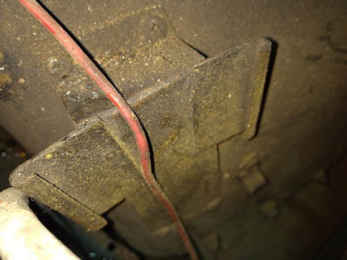
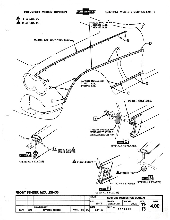
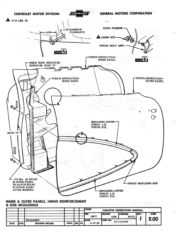
Removing the trim piece running at the bottom of the front fenders from the
wheel well to the door! The last post on this trim near the door is not
accessible. Do you break it off and epoxy it back on when replacing? Thanks
Dennis
From:
John Spencer, Red River Chapter Advisor:
Attached is the explosion of how the cove trim mounts. The front clips (2) can
be removed with the nuts that penetrate the fender (view C). I believe these
are accessible by removing the splash panel behind your tire well. The back
clips (2) are not - they are screwed on (see view D). You can pop the molding
off from the bottom edge or you can slide (in some cases) the trim off the
clips. Take your time here and be careful, don't bend the trim. Good luck.
From:
Bill Huffman, Michigan Chapter President:
Dennis,
Please don't break
anything off.
Check the pictures in
your 1959 Corvette GM Assembly Manual or in the Corvette Central C-1
Catalog.
The trim fasteners
are all assessable by either removing the splash pan inside the front wheel
well or by removing the interior kick panel.
The one closest to
the door is friction-hold clip that is fastened to the fiberglass body by a
small screw.
Once all the other
clips are removed, carefully pull the stainless trim horizontally away from
the body to avoid bending it.
Bill Huffman, Pres.
Michigan Chapter SACC
**********
01/27/2025
Hello,
I am hoping to pull the camshaft out of my 1958 Corvette, 283 cubic inch
engine and replace it with a new one, with the engine still installed in the
car. I know pulling the engine out would make for an easier installation,
but because of the lack of space and ceiling height in my garage, I have
decided to do it with the engine in the engine bay,
I have a few questions in regards to cam replacement in this car. Will the
X bars on the core support be in the way of the cam coming out and the new
one going back in? Will the sway bar be in the way? If I have to jack up
the engine to get by either of these possible obstacles, will I have to
unfasten the transmission mount and will I have to remove the driveshaft? I
know that I should remove the fuel pump. Since that isn't all that easy in
that tight spot, could I just loosen the bolts to the very end? Would that
be enough to lower the pump push rod enough or do I have to drain the fuel
tank and pull the pump out?
Thank you so much for your help.
Michael
From:
Verle Randolph, Red River Chapter VP:
You
should not have to drain the gas tank. unbolt the fuel pump, don't
disconnect fuel lines.
Remove:
carburetor and distributor
Intake manifold
Push
rods and lifters
Fan,
pulleys, fan shroud
water pump
Crank balancer
Fuel pump and pump pushrod - yes , it is a pain to reinstall but can be
done.
Timing chain cover and timing chain
Leave cam gear so you can pull the cam out some
Pull
cam out a few inches, remove cam gear
Remove grill teeth. May be able to leave the grill surround.
At
this point you can look at the cam position and the core support cross bars
to see how much, if any you need to lift the front of engine to get the cam
out.
Minor lift of the engine should be possible without disconnecting the
transmission.
Are
you replacing cam bearings?
Reassembly:
Turn
crank so piston 1 is top dead center.
lubricate cam bearings
lubricate cam lobs with high quality break in grease, be generous
install cam carefully to avoid moving /damaging bearings
turn
cam so the #1 intake lobe will allow the intake valve to be
closed. verify.....don’t ask why I say
verify.....
install cam gears with desired offset
reinstall every thing else.
Verle
From:
John Spencer, Red River Chapter Advisor:
Remove the fan, water pump (block the front of the engine - the water pump bolts
secure the front engine motor mount)., the harmonic balancer and the timing
cover. You can then project what you need to clear the cam when removed. I
don't believe the radiator support cross braces or the sway bar will interfere,
but better to be safe than sorry. The radiator definitely has to be removed.
If you do experience any interference, you can jack the motor slightly without
disconnecting the rear mount, drive shaft or shifter. If you do have to jack the
engine, pay attention to the exhaust and clutch cross shaft also. Removing the
fuel pump is probably the most difficult part of the job. Leave it alone unless
you run into a serious problem. Good Luck.
From:
Larry Pearson, SoCal Chapter Advissor:
Michael, the problem with the fuel tank that you must address is that the
fuel tank is located higher than the fuel pump, and when you disconnect the
line from the fuel pump, a syphon results and the entire gas tank will empty
onto your garage floor if you don't break the syphon. This is done by
removing the gas tank cap and taking your air hose and blowing the gas in
the line to the engine back into the gas tank. This breaks the syphon. To
be extra safe, plug the line at the fuel pump until you reconnect it to the
fuel pump.
Larry Pearson
**********
01/22/2025
I have a 1959 corvette that needs some fan shroud parts. I have original style
top and bottom fan shrouds, but need the two side extensions. Will the
reproduction ones that have been made in the past fit with the original top and
bottom shrouds or do I need to find a set of original side extensions? I
believe the 1958 and 1959 fan shroud components are the same, however I see
reproduction side extensions for sale that claim they fit from 1956 thru 1959.
Another possibility that may be viable is using s reproduction lower fan shroud
and extensions with my original top shroud. This is another reproduction item
that claims to fit 1956 thru 1959. Would this option work? Thanks! John
From:
Larry Pearson, SoCal Chapter Advisor:
John, the 1958 and 1959 Corvette fan shrouds consist of four separate
pieces: the large top assembly and a three piece bottom assembly. The three
piece bottom assembly consists of a center piece (which apparently you have)
and a left and right outer piece (which apparently you do not have), The
major Corvette parts suppliers sell the bottom three pieces, but you will
probably will have to buy all three, since I don't see them being sold
separately. Apparently, the three piece bottom assembly is the same (or
very similar) for 1955 through 1959.
Starting in 1960, a five bladed fan option became available with a fan
clutch. This necessitated the design of a shorter three piece fan shroud.
The five bladed fan with fan clutch became standard for 1961 and 1962. If
you want to go with the five blade fan and fan clutch, you will have to
purchase the three piece 1960-62 fan shroud.
Larry Pearson
**********
12/13/2024
I will be joining very soon and thank you for answering my question.
I have done some research and if this info is correct all 57 corvettes with rpo
276 had black rims and like mine standard wheels body color
My question now is even if I buy the 63 rims they only offer standard bias plys
that are same size as 5” rims or 205/75R/15 so what would I actually gain?
Tom
From:
Verle Randolph, Red River Chapter VP:
Tire size is why I decided to get 15X7 wheels and get the appropriate size
tires for that wheel.
Switching to good radial tires will give a major improvement in ride and
handling over bias ply even with 15X5 wheels. Larger tires help handling.
From
Larry Pearson, SoCal Chapter Advisor:
Tom, the proper size radial tire for a 5" rim is 195.75 R15. I have been
using this tire size on my 62 since the late 70's, and the ride and handling
are wonderful. However, currently this tire size is pretty much obsolete
and hard to find. None of the major tire makers currently manufacture this
size, as far as I know. Today,
most of the owners in my SACC Chapter are using 215.75 R15 tire size on
their 5" rims. The thinking is bigger is better. But it is not. Big,
heavy tires increase the un-sprung weight of each wheel and results in a
reduced ride quality. Handling is not what it should be because a 215 tire
should be on a 6" rim to work properly. Also, the wider the tire, the
harder a C1 is to steer.
I used to Autocross my 62 and went to the C2 5.5" wheels because none of the
performance radials available at that time were designed for 5" wheels. But
you are not racing your car.
I suggest that you stay with your 5"wheels and try to find some decent 195
tires. If you can't find decent 195 tires, go with 205 radials. Do not put
215 radials on your 5" wheels.
Larry Pearson
Additional question:
I have decided to put my original rims tires and wheel covers in storage.
I am going with the Zip 15.5 and radials 205 75R 15.
I was fortunate to win on eBay 57 Dog dish caps
I know you told me but I must expand the center opening and what type of tool if
any do you recommend ?
I am creating my own 276 RPO
All the best
Tom
Larry Pearson:
Tom, buy a grinding wheel approximately 1" diameter x1" long that works with
a hand drill. Enlarge the hole by grinding in a rapid continuous circular
motion in an effort to make the enlargement uniform. As I recall, you don't
have to remove much material to get the hole to fit the front hub. Do all
four wheels, even though there is no interference with the rear axle.
Larry Pearson
**********
12/11/2024
Hello
I have a 1957 corvette fuelie all original color and all matching numbers.
I would like to put aside the original wheels and tires
I want to go with 5.5” wheels as a 276 option
will reproduction 63 rims from Zip work and what size tires would be best
My car was judged at 98.3 and it is now my daily driver using av fuel from
airport!
EL stamping in cascade green and I have dealer invoice and all owners info
not a trailer queen
Thank you
Tom ,Member 66335
Sent From My iPad Mini
Thomas
From:
Larry Pearson, SoCal Chapter Advisor:
Tom, as you probably know, "original" 5.5K wheels used on C1 Corvettes are
extremely rare and expensive. If you can find them, expect to pay at least
$1500 each for them. The standard steel wheel on the C2 Corvette is 5.5
inches in width, and they will work on your 57 if you modify them to fit
over the front wheel hubs, which are larger than the C2 front wheel hubs.
Use a hand drill and cylindrical grinder to enlarge the hole. It doesn't
take much effort to do this. Do all four wheels. As for tires, I recommend
using 205.75 R15 tire size radials with the 5.5 inch wheels. Neither the
original 5.5K wheels nor the 5.5 inch C2 wheels have the nubs that allow the
use of the C1 wheel covers. You will have to use "dog dish" hub caps.
Larry Pearson
From:
Verle Randolph, Red River Chapter Advisor:
I chose to go with 15X7 wheels with 215 70 15 radial tires. Picked tires for
wet and dry handling. Vastly improved ride and handling over the original
15X5 wheels and bias ply tires.
Now running small hubcaps. I can run the full cover hubcaps, add the nubs to
wheels with a MIG welder.
My car is a driver, not a show car, mostly original unrestored 57. See
picture below

**********
12/09/2024
Can your members suggest a reputable garage to work on my 1958 Corvette to
replace the trunk springs and hood release cables and routine servicing?
Close to downtown Phoenix is ideal.
thanks
dennis
From:
Verle Randolph, Red River Chapter Advisor:
My first idea it for you to go to local car shows and cruises and ask people
there. Also locate local Corvette groups and go to a meeting.
A general suggestion is to look for a car repair shop that is old and has
older workers. Young mechanics are trained to plug in a computer and do what
it tells them to.
Trunk springs and hood release are truly a paint in the back, just replaced
my 57 hood release. It is uncomfortable (take seats out) and takes some
time. Suggestion, apply some lubrication to the hood release cables and work
them in and out before installing. That makes them work a lot better/easier.
Been too long since I had the trunk springs out, don't remember how I did
it.... vice grip and large screw driver?
Good luck,
Verle
**********
I’m having the same problems I’ve read about concerning Al Knock’s tops. I
can’t close the storage lid without jumping on it when the top is down. Judging
is not my thing and the only time I’ll drive my ’59 in the rain is if I misjudge
the weather. So, can anyone recommend a soft top manufacturer whose product
will allow me to close the stowage lid comfortably?
From:
Larry Pearson, SoCal Chapter Advisor:
Dave, Al Knock's tops use a material that is at least twice
as thick as the original material that Chevrolet used. I have a 62 that
came with an original top. It literally fell into the top compartment.
When it finally needed to be replaced, I bought a service replacement top
from JC Whitney (now long out of business). The grain in the vinyl was
wrong and the rear window was wrong, but it easily folds into the top
compartment, because the material was thin, like the original material. I
bought a top from Al Knock for my 1960 and experienced the same problem that
you did when I went to fold it down.
My advice to you is that you contact Al Knoch and see if you can get him to
custom fabricate a top for your 59 out of thin material, because you don't
care about originality. A big part of Al's business today is
custom interiors, so he should be able to do this for you. If he won't or
can't do this for you, contact a local upholstery shop and see if they can
purchase an after market top made of thinner material.
Larry Pearson
**********
12/04/2024
What Lube do I use in the Steering gear box. in my 58 corvette? Thanks Russ
From:
Michael Cappozio, Ohio Restorer:
You may get multiple answers but I’ve had the best luck with Lubriplate 630-AA
Multi Purpose Lithium Grease. It’s available in a 10 ounce tube which makes it
extremely easy to add to the steering box. Sold through many internet
suppliers.
From:
Bill Huffman, Miichigan Chapter President:
Russ,
After struggling for
years with C-I steering gearboxes that leaked the high viscosity trans &
differential lube all over the garage floor, I started using this product---
Prices vary. I bought
mine at the local Advanced Auto Parts store.
Fill the gearbox to
the plughole with this product and check periodically as it will settle some
with worm/gear operation to stop the leaking & get you smoother steering
operation. Fill only the gearbox. Do not fill the steering column tube under
pressure with a lube gun.
I have used this for
the last 5-6 years with no problems or unintended consequences.
Good luck,
Bill Huffman
**********
10-27-2024
I have a 1959 corvette with matching numbers duel four barrel carbs and I have a
bad miss. I would like to do a vacuum test but don't know where to get the
vacuum from. There is a 5/16 inch bolt in the alum manifold next to the
distributer but I cannot find a adaptor to hook this up to a hose to attach to
the vacuum meter. Distriberator is a mechanical advance so no access there. I
can't find any access on the carburators. Don't know what to do and hope someone
has a way to get vacuum to the meter for a test. I'm greatful for any help you
may offer. Thank you very much. Mike
From:
Larry Pearson, SoCal Chapter Advisor:
Michael, I can't figure out how a vacuum test will help to solve your
engine's miss. Did this miss suddenly appear? Did something change that
might have caused the miss? You need to determine which cylinder is causing
the miss. Disconnect each spark plug wire separately from the distributor
while the engine is running, and this should help you determine which
cylinder is causing the miss. Then remove the cylinder's spark plug and
inspect it for damage and for a visual sign that the plug has been firing.
The electrode should appear white if the plug is firing. If the plug has
not been firing, the electrode will have a dark color. If the plug
electrode is wet with coolant, you likely have a blown head gasket, which
will allow engine coolant to enter the cylinder, shorting out the plug
electrode. If the plug electrode is dark, but dry, check the spark plug
wire for continuity. The carbon string type ignition wires normally have a
resistance of about 10,000 ohms or less. The rubber insulation might be
cracked causing the spark to ground out. To check for this problem, remove
all ignition shielding, and observe the ignition wires in the dark with the
engine running. If you see any flashing, replace all of the spark plug
wires. If the wire tests good, remove the distributor cap and inspect the
electrode for the offending cylinder for signs of damage. Look for signs of
a carbon track between cylinders that could be causing cross firing between
adjacent cylinders. Is the distributor cap cracked?
If everything looks good up to this point, you need to do a compression test
of the offending cylinder. Possible problems this test will determine is a
burned exhaust valve or improperly adjusted valve lash for that cylinder.
Possibly a cam lobe for one of the two valves in that cylinder has gone
flat, resulting no valve action. Possibly a broken rocker arm or broken
valve spring. The valve springs in this engine are coaxial. The thick
outer spring normally is the one that breaks. leaving the flat wire inner
spring.to keep the valve from falling into the cylinder (which will destroy
the engine). The flat wire inner spring prevents resonances and is much
weaker than the outer spring.
That is all that I can think of.
Larry Pearson .
**********
09/29/2024
I recently purchased a 1954 Corvette from an estate sale that has the
original six cyl. but the tranamission was changed out some time in the
70's.
The car has not been on the road for at least 25 years. My problem is the
starter that is in the car (after having it rebuilt) does not engage or
mesh up to the
168 tooth flywheel that is in the car. I took all the spark plugs out and
turned the engine over with a flywheel tool. I also counted the teeth on
the flywheel.
The starter has 9 teeth on it. The car is still a six volt
system............My question is how many teeth should the flywheel have,
and how many on the starter ?????
The place that rebuilt the starter said that in was either for a 57 or 58 .
I have found a starter for a 53/54 Corvette, but was not sure if it would
do me any good if
I have the wrong flywheel in the car..............
I was advised by Larry Spillman to reach out to you for your help.
Thank you in advance, for your response.
Tim
From:
John Spencer, Red River Chapter Advisor:
The number of teeth is not the important issue. The diameter of the flywheel
is. I see no reason you would have a problem - if you can turn the engine with
a flywheel tool - the starter should engage. NOTE ! the starter for a 57 or
58 is a 12 V starter it will not work in a 6V system. Does the starter bendix
engage ? When you hit the starter with voltage the starter gear should jump to
the end of the starter shaft. You can observe this with the starter out of the
car, on the bench.
From:
Bill Huffman, Michigan Chapter President:
Chicago Corvette has
a used original 53-55 flywheel for sale.
Bill Huffman, Pres.
Michigan Chapter SACC
**********
08/17/2024
Hello Jack,
Recently I got a fully restored 1956 with a three speed standard
transmission. The odometer does not have any miles recorded on it. The
speedometer isn't working and I have found that the gear on the lower end of
the speedometer cable is not meshing with the gear on the tailshaft. First
I changed the gear and installed a new one. It still didn't mesh. Then I
put the gear into a spare transmission and it is still the same. If I
manually pull the fitting and gear out a little, some fiction is felt, but
you can still turn the gear freely with a piece of speedometer cable. The
mating gears on both transmission tailshafts look real good. It seems like
a larger gear is needed. The cable gears that I have been using measures
about 3/4 of an inch wide. Are wider gears available and am I using the
wrong gear? Thank you.
I have a 1959 corvette with matching numbers duel four barrel carbs
and I have a bad miss. I would like to do a vacuum test but don't
know where to get the vacuum from. There is a 5/16 inch bolt in the
alum manifold next to the distributer but I cannot find a adaptor to
hook this up to a hose to attach to the vacuum meter. Distriberator
is a mechanical advance so no access there. I can't find any access
on the carburators. Don't know what to do and hope someone has a way
to get vacuum to the meter for a test. I'm greatful for any help you
may offer. Thank you very much.
From:
Larry Pearson, SoCal Chapter Advisor: Michael, I just measured the outside diameter of the speedometer gear in a
spare transmission for my 1956 Chevy Bel Air. It is 0.875, or 7/8 inches.
If your gear measures 3/4 inch, then it is 1/8 inch too small, and that is
why it doesn't mesh with the transmission gear. You don't say what your
rear end ratio is. The standard ratio for a 1956 with a 3 speed
transmission is 3:70. If so, the gear that you need is light green with 22
teeth. Corvette Central lists this gear as part number 531119.
Larry Pearson
**********
08/17/2024
Car Stalling out after about ½ hour of driving.
After about ½ hour of driving, I get a big shake, then the car just dies.
If I let it sit for about 10 minutes, it starts up just fine but only runs for
about 5 to 10 minutes.
We have the following as new:
Distributor
Wires
Plugs
Coil
Battery
We have emptied the gas tank (No floating particles in it).
We have changed the fuel filter.
NOTE: It’s a 350 V8, my fuel injection is long gone.
1957 car.
I don’t know what to do. Any ideas?
Joseph
From:
Verle Randolph, Red River Chapter VP:
My first guess is a heat related
ignition problem. Check coil (new coils can be defective). When it stops
open hood and see if coil is hot.
The condenser in the distributor may be defective.
Check wire from coil to distributor.
Hopefully others will speak up with other ideas.
Verle
From: Larry Pearson, SoCal Chapter Advisor:
Joe, are you using a distributor with points or a distributor modified to
use electronic ignition? I you are using points, check the ballast
resistor. It is the white ceramic thing mounted below the windshield wiper
motor. The resistance should be 1/2 ohm (Corvette), or 1.5 ohms (sedans).
Either one will work fine in your car. This resistor gets quite hot when
the engine is running, and maybe it opens circuit when it gets hot. The
symptom is when the engine dies and you try to restart it, it starts when
the starter is cranking and then immediately dies when you release the key.
This is because the ballast resistor is bypassed (shorted out by the starter
solenoid) when the starter is cranking. This increases the voltage to the
coil while the starter is cranking and causes the coil to give a hotter
spark. The large current flow to the starter causes the battery voltage to
drop below 12 volts while the starter is cranking. The running voltage in
the car is 14.2 volts when everything is up to normal temperature. This
voltage is necessary to keep the battery fully charged.
If you are using electronic ignition, that may be failing when the
electronics gets hot. Pull the wire from the coil to the distributor and
see if there is a spark when the engine dies. If not, the ignition is the
problem.
Larry Pearson
**********
08/08/2024
Strange looking gas tank drain plug. It has a 7/16th bolt in the center of other
cover insert. Is their a trick to removal or just take out the 7/16th bolt. I
did not want to snap off the small bolt. 1957 Corvette
From:
Verle Randolph, Red River Chapter VP:
I saw your picture.
Have you tried to remove the bolt?
Is it so tight you are afraid of breaking the bolt?
I suggest you clean the area as much as possible, apply a good penetrating
oil and try to remove the bolt. Use a six point socket and work the bolt
back and forth. You may need multiple application of penetrating oil over a
period of time.
If there is gas in the tank siphon as much as possible out and there will
still be some in there.
Have a container under the bolt with funnel to guide gas into the
container.
Good luck,
Verle
I also have a 57
**********
07/19/2024
Hi Jack,
Hope you are doing well. I have a 61 Corvette 270
HP what is the correct generator pulley size?
Some tell me 3 5/8” other tell me 4” would the
wrong size pulley make my tachometer not work right.
Would either pulley size use the same fan belt?
Regards,
Glenn
From:
Larry Pearson, SoCal Chapter Advisor:
Glenn, the correct generator pulley diameter for your 270 hp 1961 Corvette
is 4". The original part number for this pulley is 3711685. All 1958-1962
Corvettes with solid lifter camshafts used this pulley. The belt grove was
extra deep on these pulleys to minimize the chance of the belt coming off at
high rpm's, which these engines were capable of. With this in mind, the
effective diameter of the 4" pulley actually is 3 5/8". So the 3 5/8"
pulley will work fine for your application if that is all you can get.
Corvette Central sells a reproduction of the 4" pulley.
Larry Pearson
**********
07/03/2024
Was any part of the 60 power glide painted ? The one in my car appears to have
been painted a light to baby blue or parts of if it have been
Thanks
Frank
From:
Larry Pearsonk SoCal Chapter Advisor:
Frank, all cast iron Corvette transmissions, 3 sp, 4 sp, and Powerglide,
were originally painted with gloss black chassis paint.
This was done
just before the body drop onto the chassis. At this time, gloss black
chassis paint was sprayed on the transmission, with overspray on the bell
housing, the drive shaft, the exhaust system, the front suspension, the
brake master cylinder (which was sticking up in the air attached to the
brake line), the brake lines, front brake drums and backing plates and
lines, the front and rear sway bars, and anything else that was not already
painted. This is illustrated on page 50 of the book "Birthplace of
Legends". This book covers the manufacture of all Corvettes built at
the St Louis assembly plant, and contains many assembly line photos.
Chassis paint was a low cost solvent based black tar-like coating. It is
easily removed by all petroleum based solvents, from Mineral Spirits to
Lacquer thinner. Its gloss finish quickly deteriorates to flat. The four
speed transmission in my 1960 Corvette has never been out of the car and is
still painted with chassis paint, along with the shifter linkage and
overspray on the bell housing and clutch cover. A good friend of mine's
1961 cast iron Powerglide car's transmission was painted chassis black (that
was before he had it rebuilt, now it is unpainted).
Larry Pearson
**********
06/25/2024
You helped me last year with a speedometer gear issue and I’m wondering whether you or someone you know can help me with another issue.
I own a 61 Corvette as shown in the attached photos.  I’m trying to determine if I have it valued properly for insurance purposes.

Some facts about it.  I am the original owner, having purchased it off the showroom floor in November, 1960.
It has 89,000 original miles and has been garage kept for all but about 5 years. It has never been in an accident of any kind.
The paint is original and is in excellent condition. Except for the front bumpers (minor scratches), and one door post (pitted),
the chrome is just about perfect. Except for the clock, everything else works. The dash pad, seats and carpet have been
replaced to original condition. The convertible top looks new. It has a 4 speed with positraction.
The only negative I know of is that it does not have the original ehgine. The current engine is 350 ci with about 10,000 miles
on it and a 4 barrel carburetor.

I have no intention of selling it. My son will inherit it someday.  I just think it’s underinsured and I’d like to get a
reasonable idea of its value.
From:
Verle Randolph, Red River Chapter VP:
Hagerty has a "value tool" on it's web site that can help.
Search the internet for 61s for sale. Don't believe the prices for the ones
for sale by a dealer.
DO NOT UNDER INSURE!
A friend recently had an accident, a pickup turned into him and did major
damage to a very nice original Corvette. The Pickup owner had minimal
insurance and my friend was vastly under insured (agreed value). His
insurance company would only pay that amount. The car was totaled.
Verle
From:
John Spencer, Red River Chapter Advisor:
One owner 61 vets are few and far between. Don't think of the value of the car
as if you were going to sell it - think of it as if you had to replace it. You
can scan the WEB of comparable cars (you won't find any one owners). Bring a
trailer.com will give you some feeling of its replacement cost. Barett Jackson
and Mechum auction houses will also give you a feeling for what 61s are selling
for. Their WEB sites give you links to recent auction results.
**********
06/16/2024
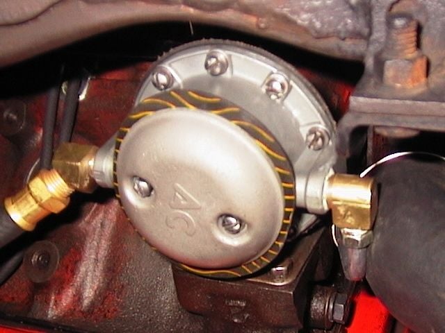
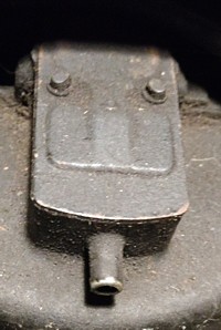
Finally getting around to rebuild of 4663 fuel pump for our 1958 Vette.
Hit a stumbling block – the bottom dish-shaped plate (with AC logo) does not
want to come apart from the body (have removed the 2 screws, of course!)
I tried some gentle hammering and prying, it just does not want to budge.
Am I missing something?
Don't want to damage it …
… Alfred
From:
Larry Pearson, SoCal Chapter Advisor:
Alfred, the pump looks brand new. Why are you rebuilding it? The bottom
cover with the AC logo and the zig-zag pattern in the gasket are completely
correct. Test the output pressure and if it is at least 5 psi, the pump is
good. Most mechanical vacuum gauges also measure fuel pump pressure. These
pumps normally last for many years before they have to be rebuilt.
If you must rebuild it, the bottom cover appears to be glued in place with
some sort of gasket cement. Take a razor blade and cut away the edge of the
gasket and then force the razor blade into the gasket around the edge. If
you do this, the cover has to come off. Do not hammer on the metal cover in
an attempt to dislodge it. It will mar the finish and may warp it. This
cover has to be sealed against leakage. If it leaks, the gas in the tank
will siphon onto the garage floor, and you don't want that.
Larry Pearson .
Additional information:
Alfred, your problem is not your fuel pump. You should never have removed
it from the engine and taken it apart. It is brand new. Nothing is wrong
with it. Now you have to figure out how to put it back together with a new
bottom gasket. And then you must figure out how to install it back on the
engine. All this is very tricky.
Your pump is not getting any fuel from the gas tank. There is no fuel for
it to pump. The gas line to the tank is obviously plugged up somewhere.
Since the gas tank is higher than the fuel pump, a siphon will set up and
gas will start flowing by itself out of the line that connects to the input
to the fuel pump. This is not happening. Remove the gas cap and attempt to
blow into the line at the fuel pump end. If you cannot blow into the line,
something is plugged up on the way to the the fuel line pickup in the gas
tank. If so, you must remove the gas tank cover and disconnect the fuel
line from the fuel tank sender and blow through it. If you can blow through
it, then the problem is with the fuel tank fuel pickup assembly in the
tank. Remove it and determine where the blockage is. There is a strainer
(filter) on the end of the fuel pickup line. Maybe that is plugged up. Is
your gas gauge working? Is the float good (not full of gas)? Take an ohm
meter and move the float arm up and down. The float moves a pickup on a 30
ohm variable resistor, and moving the float arm should vary the variable
resistance from zero to 30 ohms. If this not happening, your gas gauge will
never work.
Did the gas in the tank go bad? If so, the tank has to be removed and taken
to a radiator shop to have it cleaned. If you store the car for long
periods, put Stabyl in the tank, Auto parts stores sell it. It prevents
the fuel in the tank from going bad.
As to your questions about the fuel pump. There are two cavities in the
bottom of the pump. One is the fuel input cavity that connects to the fuel
tank line, and the second one is the output fuel cavity to the carburetor.
Fuel enters the input cavity that has a one way valve on top (the round
thing), that allows fuel to be sucked up into the cavity under the main
diaphragm. When the actuator arm is pushed down, the main diaphragm moves
up and sucks gas through the inlet valve into the cavity under the main
diaphragm. When the actuator arm is released, the diaphragm pushes the fuel
through the one way output valve and into the output cavity that connects to
the fuel line to the carburetor. No fuel ever gets into the bottom cover
under the bottom gasket. The white powder in the bottom cover never gets
mixed with gasoline. It is not the problem.
When you get the problem fixed, you must plug the line at the fuel pump to
prevent a siphon from occurring and causing the gas to empty onto your
garage floor. Connecting the line to the fuel pump does this.
Larry Pearson
**********
05/24/2024
Corvette Info:
1961 Corvette, VIN: 10867S104243
283 cu.in. / 4BBL, base engine 230 HP, orange painted valve covers.
Engine Block Number: V152438 (stamped passenger front of block), Head ID:
3774692
Powerglide
Tuxedo Black with Red Int.
Original Condition. Shows 50,000 miles, but odometer not working.
Sold new by Frontier Chevrolet, Fresno, Calif. To James and June Louttit
Second Owner: Dennis William Rowe, Fresno, Calif. (1984-2020) Rowe took
car to Hawaii for most of his ownership.
Third Owner: Steve Ricci, Victoria, British Columbia, Canada – Steve
obtained it in a trade with Rowe’s widow.
Present Owner: Doug and Angela Oakley who purchased Corvette in May
2023.
Question:
I believe Engine is original and car shows that the 50,000 miles may be close.
Could Engine have been replaced while under Warranty?
My research indicated all 1961 Corvette Blocks were stamped 3756519
Thanks for the help.
Doug
From:
Larry Pearson, SoCal Chapter Advisor:
Doug, This is not the original engine for your car. The pad on the right
front of the engine block should have two stampings. The upper stamping
should be: FXXXXDG. The F means that the engine was made at the Flint
engine plant. All C1 V8 engines were made at the Flint, Michigan engine
plant. The XXXX is the production date for your car. Example: 0627 is June
27th. The DG code is for the base engine with powerglide, which you
say that you have. The lower stamping should be 104243, the VIN number for
your car.
Larry Pearson
From:
John Spencer, Red River Chapter Advisor:
The #3756519 is not a stamped number on the engine. It is the block casting
number. The engine serial number and power train codes go on the stamp
pad. Your car's serial number & transmission code "DG" should be there.
Only 10,939 61s were built. The highest serial number is thus 110,939. The
number 152438 is outside that range. It looks like the original engine has
been replaced. The number you need to look for is the "casting number"
"3756519" \1. It is located on the driver's side - top back of the
engine behind the heads - where the bell housing bolts to the engine. It is
a number cast into the block. This tells you whether or not it is a correct
block (61 283 Corvette). The casting number on your heads is correct for a
61.
Late production 61s used a 3789935 cast engine.
**********
04/16/2024
This corvette that I may purchase has power steering and power brakes. .Is
that good although non-original?
-Bev
From:
Verle Randolph, Red River Chapter VP:
What are you planing to do with the car.
If it is a driver, there is nothing wrong with those changes assuming the
work was done correctly.
If you are buying for an investment maybe not. Historically nice original
cars increase in value more than altered cars do. That may not be the case
in the future.
Just my opinion.
Verle
**********
04/11/2024
Guys,
I have a new front clip on my '56 Vette and need help locating how to place
the badge. Does anyone have the specific measurements as to how to place the
badge?
Thanks,
Ken
From:
Verle Randolph, Red River Chapter VP:
On my 57 with original, undamaged fiberglass,
centered between headlights, bottom edge of emblem is three inches from top
edge of original grill surround trim.
Verle
From:
John Spencer, Red River Chapter Advisor:
Center of badge is 1) center of nose panel L-R 2) 6 3/4 in down from hood
opening.
**********
03/19/2024
In August I sent an email describing the valve train problem that occurred in
my 230 hp 283. With your help, before I took it apart, it seemed like I might
have a broken valve spring and possibly bent an exhaust valve. The one thing
that i knew for sure was that I had badly bent a pushrod. Before taking the
engine apart I took compression tests of all of the cylinders and a leak down
test of all of the cylinders except number three, the faulty one. The leak down
test showed that any of the cylinders that didn't show leakage from valves only
had leakage from 13 to 15 percent. so I believe the rings are in pretty good
shape.
Before taking the heads off I found that several of the rocker arms were
most likely worn because there was much side to side movement and they had
been wearing onto the sides of the valve stems. Once the heads were off I
found no evidence that a valve had been hit by the piston. Good news. The
bad news is that the lifters have extreme wear and it has been suggested to
put in a new camshaft and lifters along with doing the heads. I am trying
to do all I can to not pull the engine out even though I know that would
make working on it easier. I don't know alot about the history of this
engine. When I bought the engine, I was told it had had a recent rebuild.
I believe now that might be correct. It is very clean inside and has just a
slight ridge at the top of the cylinders. I can barely feel it. I have run
it 8000 miles
So my question is, since I have to replace the camshaft, I was thinking
about putting in a Duntov cam and solid lifters. Is there any reason that
you would not recommend that? Also my plan, as long as the oil pan will be
off, is to put in a new oil pump.
Michael
Michael, installing a Duntov solid lifter camshaft will get you practically
nothing unless you install dual quads or Fuel Injection. Your single Carter
WCFB carburetor has too small a CFM to adequately supply a high lift
camshaft. Also, the solid lifter engines had high compression pistons,
boosting the compression ratio from 9.5 to 10.5.
I cannot see how rocker arms can wear into the sides of the valve stems.
But they can mushroom the tips of the valve stems. And they could wear into
the sides of the rocker arm mounting studs. Damaged studs can be replaced
when you do the valve job. I don't understand how the push rod got bent.
Did the rocker arm adjusting nut work its way loose? Is the #3 cam lobe
worn flat?
Larry Pearson
From:
Verle Randolph, Red River Chapter VP:
From your description I suspect the cause of your problems is cam and
lifter wear. A worn cam will result in loose rocker arms. The worn
rocker arms may be because they are old. When the rebuilt the engine did
they replace the rocker arms?
I strongly suggest you pull the engine. With the worn cam and rocker
arms you will have metal particles all through the engine. The crank and
rod bearings are probably worn. You need to have the block and
everything vatted so they are clean. Pay special attention to the oil
passages in the block, make sure they are clean.
A lot of people have had cam/lifter failures on brand new engine
rebuilds. Do your research before picking a cam.
I believe all 58 Corvettes had 9 to 1 compression. Higher compression
definitely helps performance but requires higher octane fuel.
I agree you would need more carburetion to realize performance of the
Duntov cam. A different intake manifold and larger carburetor.
Verle
From:
John Spencer, Red River Chapter Advisor:
I don't know why you would use solid lifters unless you modify all
the other components necessary to achieve the performance of a solid
lifter 283. That includes pistons, intake and carburation. Solid
lifters alone means you have created a maintenance (adjustment)
routine for no other reason than to say you have solid lifters in
your engine. As far as the other issues - if you are changing the
cam I would definitely freshen up the other associated components
(lifters, pushrods and rockers). RE: oil pump - go to a high volume
pump.
**********
02/11/2024
I have a 1959 Corvette that had a non-posi rear ... I'm installing a posi
355 ratio rear ... I have seen a vent tube assembly that is for the older
Corvette's with a posi rear ... My axle tube has a small vertical vent tube that
is probably 2" long with a loose fitting cap for the vent ... Is it necessary
for me to install the vent listed for the older Corvette's which is a threaded
90 degree angle fitting with a pipe probably several feet long ... If I need to
install this threaded assembly I will need to tap some threads into the axle
tube since my vent was just a push in vent ... Any help would be greatly
appreciated ... Thank You very much ...
Jerry
From:
Larry Pearson, SoCal Chapter Advisor:
Jerry, in my opinion, a vent is a vent, and that is all you really need for
your rear axle housing, regardless of Positraction. If you are having your
car judged by NCRS, then you need to to install the vent tube assembly and
remove and plug the hole for your vertical vent. The vent tube is
illustrated in the 1959 Corvette Assembly Manual under section RPO 675. No
dimensions are given for where the 90 degree fitting is to be located. It
might be in the same location as your vertical vent, which actually may be
threaded into place. The end of the vent tube is cut off at an angle, with
the open end facing down.
With the 1959 Corvette, the available Positration ratios were 3:70, 4:11,
and 4:56. The standard ratio with a manual transmission, Positraction or
not, was 3:70. Powerglide came standard with 3:55 open only. The 3:55
ratio was not available with Positraction in 1959 in Corvette.
I mentioned the 1959 Corvette Assembly Manual. If you don't have one of
these, you can buy one from any of the major Corvette parts suppliers. It
illustrates all the details on how Chevrolet manufactured your Corvette, and
is a "must have" if you work on your car. Also, buy the Corvette Servicing
Guide, Publication ST 12. This is the only official shop manual that
Chevrolet produced for the C1 Corvettes.
Larry Pearson
From:
Michael Cappozio, Ohio Restorer: Jerry, it would be best for you to
install the proper vent if installing at posi traction differential. Also keep
in mind, you may experience some possible leakage of gear oil from the axle
shaft seals. A posi traction housing has small plates welded inbound of the
axles to keep the gear oil from pushing towards the ends of the housing tube. An
open differential housing does not have these plates in place.
Michael
Capozzio
Classic Corvette Restorations
Chardon, Ohio
**********
01-14-2024
My question is on the date code...
The last # 8 on code L178 does the #8 specify the model year of car that the
axle was made for ?
OR ...
The actual date that the axle was molded / manufactured ?
GM # 3725899 / L178
L=November / 17 = 17th Day / 8=58
One more question the metal ID tab on the bolt at the two o'clock position
is that from under car facing the rear of car or looking in from back of car
towards the front ?
I was under there and actually didn't see it in either position but I see
they sell the tabs to put back in place when restoring car / axle.
Thank you
Barry
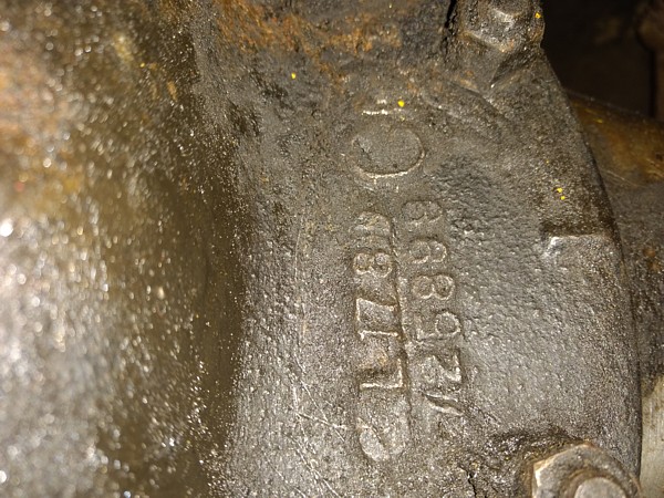
From:
John Spencer, Red River Chapter Advisor: The number you are referring to
(L178), is the casting date of the carrier. L=Dec. 17th - 1958. The Ratio tag
you question is located at the two o"clock position when viewed from the FRONT.
Follow up question to date code on rear axle
L178 (
November 17, 1958 )
Then this axle L178 was made for an early model 1959 Corvette ?
According to internet the last 58 model to roll off the assembly line was in
August of1958. ( According to internet ).
Do the 1959 cars have 1958 dated axles ?
I was guessing that maybe they put month ( L) day (17) then the actual
model year of car to be fitted on the stamp (58). But that is a guess and
would only make sense to me making mine a original 1958 model year rear
axle.
L
November 17 day and made in 1957 but for a" 58 " model - L178
My 1958 has a couple signs of being an early model car besides the " born on
date" look up tool and my low VIN #
I have the short tab hood latch location hole ( but not short tab ) and the
door chrome trim end pieces having no screw hole from the top. The chrome
door end pieces have a clip and a screw from underneath creating a smooth
finish from the top with no visible screw hole.
Attached is a picture of a date stamp on boot cover hinge area and my
original and replacement hood latches which isn't the short tab but has the
short tab location hole (two holes). The original shown has the long tab
with two holes and my release cable ran up from underneath to the inner
short tab location hole.
I am guessing that this was the solution during the transition from short to
long tab hood latches.
I couldn't find short tab replacement latches and the "new" replacement
latches only have the outer hole as shown in photo.
In order to use long tab replacement latch I drilled the second inner hole
to accommodate the original cable hold down bracket guide location and now
they look like my original two hole long tab latches.
If I changed the cable guide bracket to accommodate outer hole I would have
had to drill to many new holes in firewall to install which I chose not to
do.
The date stamped under the hinge on my boot cover is dated
January 30, 1958 contradicting the birthday website results by a bit
( 6 weeks ).
It may have taken the extra 6 week trip down the assembly line while they
were trying to figure out the hood latch assembly. Lol
It took me about that same amount of time. : )
Sorry I went a little off topic on rear axle but it is all production date
related.
Thank you for all your help.
Barry
From:
Bill Huffman, Michgan Chapter President:
Barry,
The
differential in your 1958 Corvette was cast on
Nov
17, 1958, which is at least 3 months after your car could have been
built.
So, it
can't be original to the car, if you care.
Original
date coded parts should be 3 months to 2 weeks prior to vehicle assembly.
The
number below that is the casting number 3725899, so it is a GM, non-posi
differential.
On the
same surface but on the opposite side of the pinion emboss you should find
two capital letters that identify the original ratio & GM vehicle model as
well as a stamped date of differential assembly.
A 1959
Corvette without positraction, should show the letters AE for 3.55, AH for
3.70 or FJ for 3.70, manual trans & metallic brakes.
To
determine the axle ratio of what some previous owner has installed, turn the
rear wheel exactly one revolution and count the number of driveshaft
revolutions.
Depending
on what its original application was, it could be anywhere from 3.08, 3.36,
3.55, 3.70, 4.11 to 4.56.
Base for
your car was 3.70:1 w/ manual trans or 3.55:1 for a power glide automatic.
A lot of
stuff gets replaced in 65 years of somebody else owning your car.
Good luck
with your project,
Bill
Huffman, Pres.
Michigan
Chapter SACC
**********
01/08/2023
Was wondering if anyone had a scale drawing of the heater defroster diverter
box cardboard components. I'm considering making one, my 59 is a driver not
being judged. Thanks Dennis
From:
Bill Huffman, Michigan Chapter President:
Dennis,
I made a
heater defroster box for my 1960 many years ago before reproduction parts
were available. I made it from furnace duct galvanized steel, using the old
broken cardboard heater box as a pattern. If you don't have your old one,
you can usually find one at any Corvette swap meet or on e-bay.
Paint it
matte black and nobody will even notice. It is still in my car & works fine.
Good
luck,
Bill
Huffman, Pres.
Michigan
Chapter SACC
From:
Larry Pearson, SoCal Chapter Advisor:
Dennis, Corvette Central sells a complete defroster box with hoses for about
$200. Their part number is 455120. I assume that you have the metal part of
the heater and just need to replace the pressboard defroster assembly. I
very much recommend that you buy the Corvette Central reproduction, because
its shape and complexity would take an enormous effort on your part to
reproduce. The price of the reproduction from Corvette Central is very
reasonable, in my opinion.
Larry Pearson
**********
01/03/2024
I have a new/old Ecklers one piece front clip from the front of the
windshield forward for a a 1956 or 1957 Corvette. It came with my 1956 project
that I purchased in 1991, but was never bonded onro a car. I bought a one piece
clip that includes the upper dash to use instead. I have someone interested in
buying my original clip. but there is a question on how the grille oval would
attach since the area around the opening is just flat fiberglas with no
reinforcement. Is there anyone on the panel that is familiar with one of these
one piece units that can shed some light on how the grille oval would attach?
Thank you,
Michael
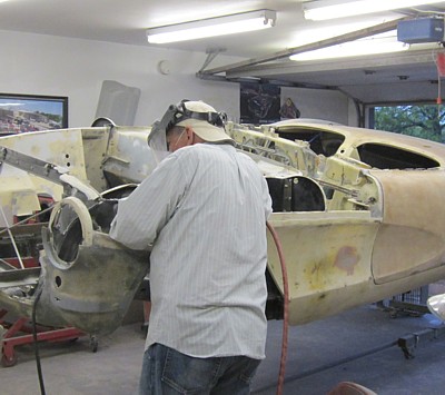 From:
Bill Preston, Red River Chapter Advisor:
From:
Bill Preston, Red River Chapter Advisor:
The chromed grill oval has 5 vertical metal braces that strengthen the grill
oval and the oval
just bolts to the fiberglass with a metal flat washers behind the brackets.
I am assuming that the opening for the
grill has been cut out according to specifications. (Picture attached of
shape of the factory opening)
I installed one from Eckler's in about 1975 and didn't have to do anything
to reinforce it.
Just be sure you have the proper brackets (picture attached), washers and
nuts that are
meant for the installation. The grill ring installs using the black vertical
brackets before any
part of the actual grill is installed into it.
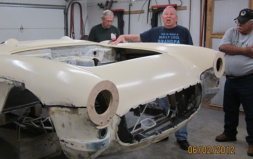
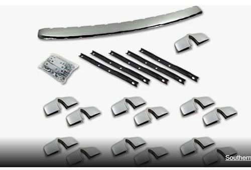
From:
John Spencer, Red River Chapter Advisor: I don't believe there is any
reinforcement around the 56-57 grill opening. The mounting points are slots in
the glass - the grill oval is mounted directly to the glass with studs in the
oval and supported with a retainer plate, washer and nut (see illustration).
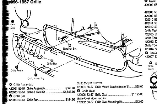
**********
12/10/2023
Hi
I have a 58 and I am installing a new gas tank, filler neck grommet and hose
etc.
It is so tight in the filler neck area. So far I put in the grommet then
slid the filler neck in. Then I managed to put the hose and inner hose clamp
on.
Now I was thinking about carefully letting tank drop in and attaching the
gas tank side of hose on it's tank drops in.
I am guessing the grommet will come loose at some point.
Is there a procedure you can suggest for me ?
Does the grommet go on last ?
If so how ?
Persistence, some grease and a side patience ?
I am working alone so it's a tuff, tight fit.
Any suggestions will be appreciated
Barry
Oh any suggests on removing three layers of paint ?
Brand of stripper ?
Sand paper ?
Razor blade ?
All three ?
From:
Larry Pearson, SoCal Chapter Advisor:
Barry, I think that you got it right. Install the grommet, then push the
filler tube into it from inside the tank area, then install the tank and
finally, install the rubber coupling hose and clamp it down securely at both
ends. Use Sil Glide silicone lubricant if you need it. Do not use
petroleum based lubricants on rubber.
Inside the gas filler area there is a drain hole. In the gas tank area
there should be a rubber hose connecting a fiberglass nipple on the other
side of this drain hole to a hole at the bottom of the gas tank area going
under the car. This drains gas spilled in the filler area directly under
the car. This helps eliminate gas fumes from getting into the car. With
the gas tank out of the car, installing a new drain hose is very easy if it
is missing. Make sure that you have installed a rubber hose from the gas
tank vent to the gas filler area, where is is clamped in place.
When installing the gas tank cover, be sure to completely seal it to prevent
gas fumes from getting into the car. Use 3M Strip Caulk to do the sealing.
That is what GM originally used to seal the tank cover. Originally it was
light gray, but only black is available
today. It has a clay like consistency and is easy to work into
place.
Do not use chemical strippers on fiberglass. It will damage the fiberglass
gel coat. Wet sand using 3M wet or dry sandpaper, 400 grit. Do not sand
through the gel coat. If your car has damaged fiberglass, have a
professional repair it. You should have a professional prepare and paint
your car.
Today's automotive paints are extremely toxic, and have to be used
with a pressurized suit in an approved spray booth.
Today, new cars are painted by robots. Automotive lacquer, which
your car was originally painted with, is no longer available.
Larry Pearson
From:
John Spencer, Red River Chaoter Advisor:
Barry - John Spencer here - I have stripped and painted a dozen or more
Corvettes. Most advisors caution you against using any kind of chemical
strippers - but - used properly they will make the job removing original + paint
easier and give you a better end product. Here is my experience - First only use
a quality stripping agent. Purchase it from an automotive paint supplier, not
your local hardware store. Second use with a lot of water (running hose).
Other items needed 1-rubber gloves 2-plastic bondo spreader 3-empty coffee can
or other suitable container 4-disposable paint brush 5-steel wool. Process:
Paint a coat on 2x2 square area - let the stripper do its job - remove the
stripped paint with the plastic spreader - repeat this process until you get
down to the original primer. You can work two areas at once - coat area 1 ,
pause for a period of time, when it’s ready to strip - coat the second area. By
the time you’ve stripped area 1 and added a second coat of stripper - area 2
will be ready to address. The first container is for stripper tho second
container is for the stripped paint. The rubber gloves are to protect you
(heavy rubber not latex shop gloves). When you get down to the primer coat -
apply your stripper and scrub it with your steel wool while applying running
water to the area until the surface is clean. This will remove stripper residue
and not damage the glass or gelcoat. When you’ve done this properly - you end
up with a clean smooth surface. A light wet sanding and you’re ready for
priming. If you need additional info I can send you a photo guide of this
process
Caution: Stripper is very caustic - it will burn you if contacted and should
be used only in a well ventilated area
**********
12/08/2023
Does anyone know if I can put 15" x 7" American Racing Torque Thrust D wheels
on Wilwoods 11" Disc Brakes? This is a 58 Corvette. I have tried both
manufactures and nobody can help. Thanks Russ
From:
Bill Huffman, Michigan Chapter President:
Russ,
Not
enough info in your request for me to give a definite answer.
Which
came first, the 11" brakes or the 15 x 7 wheels?
Have you
already bought the parts & can't make them fit or is this a new combination
you want to try out?
!5 x 7
wheels are too wide for a 1958 Corvette because they will rub on the front
inner fenders when attempting to turn.
In
addition, steering effort in a '58 with 15 x 5.5 O/S stock wheels is
difficult enough with a 17" steering wheel without the added resistance of
the larger footprint.
Corvette
Central sells a complete disc brake set kit that will fit inside the stock
15 X 5 Corvette wheels. With this kit, you can mount any wheel you choose
as long as it doesn't rub on the inside.
Bill
Huffman, Pres.
Michigan
Chapter SACC
From:
Larry Pearson, SoCal Chapter advisor:
Russ, I used to slalom race my 62. I tried wide (I don't remember how wide,
but wider than 5 1/2 inches, which I was running) Torque Thrust Wheels with
low profile tires (to avoid fender contact). I could barely steer the
car.
It is important that the wheels used on the front not be offset from stock.
That is, the center line of the wheel must be exactly over the large inner
wheel bearing, which is made large to carry the vehicle load. The small
outer bearing just assists with cornering loads. If the wheels are offset,
part of the vehicle load is transferred to the small outer wheel bearing,
and can result in early failure. Offset wheels are not a problem in the
rear.
The wheels that you are considering are undoubtedly designed to be used with
disc brakes, and, therefore should work fine. The maker of the disc
calipers shouldn't matter.
Larry Pearson
**********
12/2/2023
Greetings, I am thinking of buying an early corvette 57 to 60....Is it possible
to find an original driver for about 75,000.?....I am retired from the medical
profession and live in MA......Your website is spectacular....Thank you..
Bev.
From:
John Spencer, Red River Chapter Advisor: Yes. You should be able to find
a decent driver in good condition (probably restored or up graded). First place
to look is your local corvette clubs or NCRS Chapters. You
are most likely to get a true evaluation of a Classic from a personal owner. You
will pay a premium through a dealer. A good auction site is "Bring A Trailer".
From:
Larry Pearson, Southern California Chapter Advisor:
It certainly is possible to buy a nice 57 to 60 for $75,000. Keep in mind
that condition is important. A show car is expensive to build and will cost
a lot more because of this. If you just want a driver and do not plan to
have the car judged, a car with a non original engine will cost a lot less
than a "numbers matching" car. Generally speaking, the 57 and 58 models are
more desirable, and thus more expensive, the the 59 and 60 models. The high
horsepower cars with four speed transmissions are the most sought after and,
usually, the most expensive. Powerglide equipped cars are a joy to drive in
today's
traffic, but are less desirable to the Corvette collector, and, therefore,
are less expensive.
If you don't know these cars very well, you should get advice from someone
who does before purchasing. All C1 Corvettes went through a phase when they
were only worth a few hundred dollars, and many of the owners at that time
abused them terribly. Accident damage has always been very expensive for
Corvettes, and many repair shops cut corners, or were incompetent, and did
not make lasting repairs. Unlike metal cars, damaged fenders don't unbolt,
and have to be repaired in place by highly skilled technicians.
The above advise generally applies to any vintage car, not just Corvettes.
I wish you the best of luck with your search.
Larry Pearson
From:
Verle Randolph, Red River Chapter Advsor:
There are other years available in the same price range, most
require work.
When I bought my 57 I planned to drive it so I did a complete
mechanical rebuild, brakes, engine, transmission, differential to
insure reliability.
When you find a car you are interested in, ask here for anyone who
lives close to help inspect it. A lot of people with knowledge are
willing to help.
Verle
**********
10/27/2023
we’ve pretty much finished the restoration of my 54 vette. But I need a
top. The current one, on car from when I bought is black, but the frame is tan.
Shouldn’t the top be tan for a 54? Also, who makes best replacement tops? AK is
out of all tops except black ones. Other suppliers have vinyl and canvas
versions available - what is recommended?
Thanks,
Mike
From:
John Spencer, REd River Chapter advisor: Correct top for a 54 is Beige /
Canvas
Below is an example:
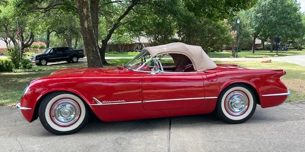
**********
10/23/2023
Hi,
I think I have found a used top for my
62 BUT it will need to be restored and painted. Do you know anyone who
does that for a reasonable fee?
Thanks.
Ivar
From:
Larry Pearson, SoCal Chapter Advisor:
Ivar, I assume that you are talking about a hard top. You don't say where
you live. I live in the Los Angeles area and know of someone who could
probably repair your top for a fair fee, but shipping something like this is
a big problem if you live far away. Corvette Central sells restored C1 hard
tops outright for $7664.15 plus $250 shipping in their most recent catalog.
Frankly, to me, that sounds reasonable for what you get. What does this top
you found need? If it is just paint, that is fairly simple. If it needs
everything, it gets very expensive.
These tops are a masterpiece of construction, but it takes an expert to
properly repair and restore one. Back in the day, the second top option was
a mere $250. What A deal.
Larry Pearson
From:
Michael Cappozio, Ohio Restorer:
Ivar, while this job can be completed by several shops, or even yourself, it is
very difficult and labor intensive. All the parts are available through
Glassworks, The Hardtop Shop in Imperial, PA. They do however offer full and
complete restoration of your hardtop. It is unfortunately quite expensive and
they work on a very long lead time. But the quality of work is next to none and
the top looks better then new when finished. They have done several tops for my
shop and I have always been beyond satisfied.
Michael Capozzio.
**********
09/15/2023
I am a 48 year member of AACA that is considering the purchase of a 1956
Corvette. As part of my research of the car I am trying to determine if the car
has its original engine. The VIN NUMBER of the car is E56S003345 which is the
latter half of the production run. The engine serial number is 0499185F56GR. The
56GR matches the dual 4 barrel manifold but I have not been able to determine if
the prefix 0499185 is within the range appropriate for my VIN NUMBER. Can you
provide any guidance on this issue? Thank you in advance for your help.
Regards,
Wayne
From:
Verle Randolph, Red River Chapter Advisor:
Wayne,
That I know of, there is no known correlation between the 56 engine sequence
number and the VIN of the car. The higher sequence numbers tend to be on
later cars. I hope someone can provide a better answer to that question.
The casting numbers on the back of the block will help. On the bell housing
flange there will be a casting number on one side and a casting date on the
other side.
Also remove valve covers and get the casting number and casting date for
each head.
Your head casting numbers should be 3731762
Your exhaust manifolds should be 3731557 Left and 3731558 Right
If you can provide the above casting numbers and casting dates it will help
identify the engine.
Good luck,
Verle
From:
John Spencer, Red River Chapter Advisor:
Wayne - Vin numbers were not stamped on engines in 56 - correct. Here is
some info to help you determine the authenticity of your engine. First -
check the engine casting. This is located on the bell housing flange of the
engine. 56 casting is 3720991. On the opposite side of the engine is the
date code the engine is cast. Documented Serial Number E56S003344 was
produced
August 8th, 1956. Your date code should be June-July
56.
The closest S/N to engine # to yours I find is:
S/N E56S002931 = Engine 0620340F56FG
The closest engine # I find to yours is:
Engine # 0402424F56FG = S/N E56S001939
It appears your engine is from an earlier 56 than yours. The date code
should confirm or refute this.
Even if the block you have is not be the original that came with your car -
if the casting number is correct - it is correct for your year.
**********
09/12/2023
Hi my name is Dean, a relatively new member. I have a 62 vette with a 340
hp with the original carb. After the engine and engine compartment
gets warm the engine doesn’t want to idle. I have had the carb worked on
but still have the problem. I feel like it is a heat issue. Have you heard
of this
from other owners? I have owned the car since 1964. Any help would be
appreciated.
From:
Verle Randolph, Red River Chapter VP:
My first thought is a vacuum leak.
Verle
From:
Larry Pearson, SoCal Chapter Advisor:
Dean: You need to consult the Corvette Servicing Guide, Chevrolet
publication ST-12 to help you with this problem. ST-12 is the only
official Chevrolet shop manual for the C-1 Corvettes. It is available
as a reprint from all the major Corvette parts suppliers and is a "must
have" for all C-1 Corvette owners.
There are two separate idle speed adjusting screws on the AFB
carburetor. When the engine is cold and the Carburetor choke valve is
closed or partially open, the Fast Idle Screw sets the idle speed. This
screw operates in conjunction with the fast idle cam, and is shown in
Figure 94 on page 6M-37 in ST-12. Once the engine is fully warmed up
and the choke valve is completely open, the fast idle cam no longer
controls the engine idle speed. At this point, the engine idle speed is
set with the Idle Speed Adjusting Screw, which is shown in Figure 92 on
page 6M-36 of ST-12. Adjusting this screw should solve your hot idle
speed problem.
Once you get your hot idle speed properly adjusted, you need to adjust
the two Idle Mixture Adjusting Screws, shown in Figure 92 on page
6M-36. This is easily done on a hot engine by turning each screw
clockwise, one at a time, until the engine starts to die. Then turn the
screw 3/4 of a turn counter clockwise. If these screws are open too
far, the engine idle mixture is too rich and may cause black smoke to
issue from the exhaust pipes at idle, and a rough idle. After making
this adjustment, you may have to re-adjust the engine hot idle speed.
Larry Pearson
**********
09/06/2023
Just found your website and thought a great place to ask my question.
I'm in the process of installing a soft top on my 1958 Corvette and
wondering the bow measurements for putting in the 2 pads.
If someone could provide measurements it would be much appreciated.
From the Front Bow tack strip to #1 bow
From #1 Bow to # 2 Bow
From # 2 Bow to # 3 Bow
From # 3 Bow to #4 Bow with the tack strip.
Thank you so much for your help
Tom
From:
Larry Pearson, SoCal Chapter Advisor:
Tom: These measurements are from a top that has the original pads in place,
so they should be correct. The measurements were made along the center line
of the top.
Rear edge of the header to the center line of bow #1: 15 1/2 inches
Center line of bow #1 to the center line of bow #2: 8 1/2 inches
Center line of Bow #2 to the center line of bow #3: 5 1/4 inches
Center line of Bow #3 to the center line of bow #4: 4 3/4 inches
Overall from the rear edge of the header to the center line of bow #4: 34
1/4 inches, which is only 1/4 inch more than adding up the separate
measurements, so my separate measurements are quite accurate.
Before installing the pads, lubricate all of the bow pivot points. Use 30
weight engine oil if you are not disassembling the bows from the side
frames. Use light grease if you have disassembled the bows. It is very
important that you lubricate the large slotted screw pivot point in the
center of the side frame. If you want to remove it, there is a small Allen
head set screw that holds this screw in place that must be loosened before
it can be removed. The top frame is painted semi-gloss black. Make sure
that the tacking strips are in good order.
Before installing the pads, install all six weather strips and retainers to
the side frames and adjust the top frame to fit the side windows when all
the way up. If you have a hard top, install it and make sure that the side
window stops are adjusted so that the side windows properly fit the top
weather strips when rolled all the way up. It is critical that the side
frame pivot point is adjusted to lift the center pivot to fit the side
window frame. This is done with the link that connects to the center pivot
and has the sole purpose to pull it up.
If you purchased your pads from Al Knoch, in my experience, they are at
least one inch too short. He cuts them to length with no extra material.
To make them work, in my experience, you get wrinkles in the pads. One of
our Chapter Members, Jeff Reade, installs tops and encountered the same
problem that I did. To get the proper length pads, tell the Al Knoch people
that you want the "Jeff Reade" top pads.
If you need parts, the entire top frame has been reproduced by Sully's Tops
in Fresno, California. Call 559.291.8677. Or go to
www.sullystops.com
Larry Pearson
**********
09/02/2023
I have an all original 1956 corvette that I purchased from the original owner 50
years ago. Yesterday after driving for about 10 miles I parked it for a couple
of hours. When I got in to leave, no reverse in the power glide. Today upon
further investigation it seems the transition is in drive all the time, even in
park, neutral and in .reverse it seems to be in both. I never had a problem with
the transmission before, this just came out of the blue. Checked shifter ,
linkage all seems well .shaft that goes into transmission rotates. Rear Tran
mount new 3 years ago and in good shape. I’m hoping I over looked something that
can be easily fix. Any help would be appreciated as this is my favorite time of
year to use it. Thank you in advance Tom …. 56 vet,265 duel quarts, 2 speed
powerglide.
From:
John Spencer, Red River Chapter Advisor:
If your shifter linkage is intact and operating good - the problem has to be in
the transmission itself. Sounds like you need to have a GOOD x-mission man
inspect and probably rebuild the tranny.
**********
08/07/2023
Hello SACC,
While heading to a show this
morning in
our 1958 Corvette and twenty-five miles from home we developed a ticking noise
and it especially got worse when under more power going up hills. I had just
gotten a tank of gas. So I was thinking that it could be bad gas. We decided
to turn around and go back home. At that point we noticed a little backfiring
through the exhaust when decelerating. I began to assume it was probably valve
related and when I stopped to listen it sounded like the left bank. We decided
to limp back home slowly, but within ten miles it developed a knock. Still the
noise seemed like the top end, but we shut it off once we found a safe spot to
stop, and called a flatbed. I was thinking a bent or broken pushrod. After
getting it flat bedded safely back to our garage I found that indeed it had an
exhaust pushrod that had gotten by the rocker arm and was bent and almost broken
off from hitting the under side of the rocker arm cover.
My question to the experts is what to do next. Should I put in a new pushrod
and adjust all of the valves? Should I put all new pushrods in? Should I look
at the lifters, (i've heard of collapsed lifters), or if I have to change one
should all 16 get changed? I do not know the history of the engine, but it runs
well and seems to be very clean in the tops of the heads and valve train. We
have run it only 8000 miles since 1997, without any issues.
Thank you for your help.
Michael
From:
Larry Pearson, SoCal Chapter Advisor:
Michael: From your symptoms, it sounds like your exhaust valve has stuck
partially open. The valve springs on your car are coaxial, There is the
outer spring made from heavy round wire and an inner spring made from flat
wire. Possibly the outer spring broke and the valve is being operated only
by the inner spring, which is not designed to operate the valve, and maybe
the valve is stuck partially open. If this happened the piston may have hit
the partially open exhaust valve and that was the source of the knock. If
this happened, the valve may be bent and the piston top may be damaged. I
had this happen with my 62 while I was returning from a Corvette meet out of
state. I removed the rocker arm cover and backed off the rocker arm nut and
removed the push rod. When I got home, I replaced all of the valve springs
to prevent this from happening again. And It hasn't. The springs can be
replaced without removing the cylinder heads. Another possibility is a
broken rocker arm. If so, replace all of them. I don't think that it is a
totally collapsed tappet. A partially stuck hydraulic tappet could account
for the ticking sound, but not the knock. If your car has solid tappets,
they can't collapse.
Larry Pearson
From:
John Spencer, Red River Chapter Advisor:
This is not an uncommon problem. Lifter, pushrod, rockerarm failures can be
simple or totally devastating. A surefix is to pull the heads and have them
gone through. This is costly however. If you think the problem is just in the
pushrod, first replace the lifters, pushrods and rocker arms. After you have
replaced these, you can check compression to assess the condition of the pistons
and valves. Assuming you are not pushing the 58 hard - the engine should give
you miles of reliable service
**********
08/04/2023
hi . i have a 1958 corvette ,it has been updated to a 350 zz1 with alternator
system . my problem is it seems all or most of my original gauges are out of
sync .i am thinking it has to do with the possibility of the gauges being made
to run off the generator ,possibly being of a certain calibration . could this
be possible and or is there any fix so i can retain my original gauges giving me
proper readings. any thoughts on this would be much appreciated . thanks perry.
From:
Larry Pearson, SoCal Chapter Advisor:
Perry: Your car has five gauges: Speedometer, Tachometer, Fuel gauge,
Temperature gauge, Ammeter, and engine temperature gauge.
The Speedometer is mechanical and runs off a cable from the transmission
tail shaft. If you are using a modern transmission, there might not be a
place to connect the speedometer cable to.
The tachometer is mechanical and runs off a speedometer type cable off an
adapter on the back of the generator, which you don't have. The 1962 and
later models are also mechanical and run off of the distributor. This
arrangement might work for you if you can run a 1962 and later distributor
with your ZZ1 350 .
The fuel gauge is electrical and runs off a variable resistor and float in
the gas tank. This should not be affected with the alternator.
The Ammeter is set up for the original generator and voltage regulator. The
early alternators used an external voltage regulator, like the generators
used. The later alternators have a built in voltage regulator. The
alternator conversion is very common, but I have never done this
conversion,so I cannot advise you how to do it. Modern cars use a volt
meter instead of the ammeter. This greatly simplifies the wiring. It just
measures the alternator's voltage output. The system normally runs at 14.2
Volts, even though it is called a 12 volt system. If the system is
operating at 14.2 volts, you can assume that the car's battery is being
properly charged.
The oil pressure gauge is mechanical and has a metal tube that runs to a
fitting that connects to the engine block oil gallery. I don't know if your
engine has a place to connect this gauge tubing to.
Corvette Central has a big catalog section showing modern electronic gauge
systems that they sell.
Larry Pearson
From:
John Spencer, Red River Chapter Advisor:
The only gage that should affected by an alternator conversion is the
ammeter (Battery). You might refer to later model wiring diagrams using
alternators (ie: midyears). They do wire differently
**********
08/01/2023
I JUST joined your club and THANK YOU for the previous answer concerning the
window problem. Next week I will be tackling this problem with my mentor Steve
Clifford here in Orange County CA..
I have 4 new questions. I would like to upgrade the radio and went to a
stereo shop. They have NO experience with a 62 vet. They asked me to see if I
could get some technical information for the install. Question how does
one go about replacing the radio with a direct NEW Bluetooth NO modification
radio? What parts need to be removed to do this, do you have a diagram? I want
to add kick panel speakers. How much room is there behind the kick panels?
Depth, room to install as many speakers may be too deep. How many inches of
space on the driver’s side and passengers’ side? OR is it better to buy the
speakers that are part of the NEW kick panel that they make?
What needs to be removed to correctly remove the kick panels on both sides?
Is it preferred to use the old kick panels and drill threw them or use the new
ones with the speakers already installed into the new kick panels?
Next question my gas gauge only reads 5/8 to ¾ full with the tank topped off. Is
there a way to fix that? The gauge has been grounded I have been told. Do I have
a bad gauge or is something defective?
I am thinking of adding a sniper 2 EFI system with a new fuel tank. The Sniper
version 2 just came out, Do you have any other recommendations of brands etc.
The engine is a 350 ZZ4 has anyone already done this and if so maybe you could
point me in their direction to speak to etc. I am getting some pathetic gas
milage around 9 miles per gallon for city use without any hot rodding so I think
this would help significantly and the engine should start more easily, less
exhaust smell, etc.
Thank YOU.
Ivar
Do I need to contact the local SAAC group or do you do that automatically with
my membership.
Thanks.
From:
John Spencer, Red River Chapter Advisor:
Several manufacturers offer replacement (direct fit) radios for Vettes. See
Corvette Central. These are direct fit and give you modern reception while
keeping the look of the original radio. I would seriously consider this
option before I started trying to modify my original radio.
As for speakers - replacement kickpanels are available with speakers already
mounted. If you choose to go the route of installing speakers in your
kickpanels, there is adequate room but for one brace. Remove your kickpanel
first to determine proper size and placement of your speakers. This is not
hard - remove your door sills and the surface screws holding the panels in
pace.
RE: FI - I have not used the system you propose, but properly done I believe
any good FI will give you improved performance. I would defer to the
manufacturer for help.
RE: Gas gage - I would suspect your sending unit (possibly the ground to
that unit). This is easily accessed. Remove the cover panel under the
convertible top storage area. The tank sending unit is on top of the tank.
Note - before you extract the sending unit "check the ground to that unit".
A poor ground will give you a faulty reading. You can bend the float arm to
adjust gage readings but you trade off Full vs EMPTY accuracy. Again, you
can find replacement sending units in the Corvette Central store.
From:
Bill Huffman, Michigan Chapter President:
Ivar,
Before you start
swapping radios in your 1962, Corvette Central has an AM-FM Bluetooth radio
that looks like your original Wonder Bar radio that you might want to look
at.
When you get done, it will still look like the original Wonder Bar radio.
Bill Huffman,
Pres.
Michigan Chapter SACC
**********
07/26/2023
I hope you can help me learn the correct speedometer gear for my 61 Corvette.
At 70 mph on GPS, the speedometer on the dash is reading 60 mph. I bought the
car new off the showroom floor in November, 1960 and I am very familiar with
everything that has been done to the car maintenancewise. It has the original 4
speed transmission and the original factory rear end with positraction. I
believe the ratio is 3.70. The tires are 205-75.
A few years ago, the gear at the back of the transmission broke. The shop that
was doing all my work had a gear that was laying around and that fit. Not
knowing any better, we paid no attention to the color of the broken gear or the
number of teeth. It was only many months later that I realized that the reading
on the dashboard was incorrect. I now want to replace the current gear with the
correct one but I don't know which gear to buy. The current gear is brown with
18 teeth. In asking around I have been told three different things. One said I
need to add one tooth (Natural). The next one said two teeth (Blue). The third
one said 6 teeth (Yellow).
Can you tell me which color along with the correct number of teeth that I need
to get?
Art
From:
John Spencer, Ree River Chapter Advisor:
rt - One owner ...WOW !! ... We don't see that very often. I am assuming by
the count of the gear you are trying to replace - you are talking about the
DRIVEN gear. Think of it this way - If you are wanting to increase the speed of
your speedo - you want to increase the revolutions of the cable at a set speed
of the transmission. The DRIVE gear has a given number of teeth. So each
revolution of the transmission engages that number of teeth on the DRIVEN gear.
To make the DRIVEN gear spin faster you have to decrease the
number of teeth on it. From that it is simply a ratio issue. If you currently
read 60mph and want to read 70mph, the speedo cable (GEAR) has to spin faster -
thus the number of teeth needs to be less than what you have. How much ?
Divide the gear teeth you have by the desired speed (70) and multiply that by
the speed you currently read (60). (18 / 70) x 60 = 15.4. If this takes you out
of the range of gears available, you will have to change the drive gear also.
From:
Larry Pearson, SoCal Chapter Advisor:
Art: I am referring to my 1972 Corvette Parts & Accessories catalog (P&A
30B, effective September, 1971). Here is what it says for 1956-1960
Corvettes, with the catalog part numbers:
With 3.70 axle: 3708699, 22 teeth, solid green nylon
With 4:11 axle: 3708143, 24 teeth, solid yellow nylon
The following are from a speedometer gear chart in this parts book, with no
applications given. I don't know if these will work in your car.
3860341, 18 teeth, Brown
3860342, 19 teeth, Natural
3987920, 20 teeth, Blue
3860344, 21 teeth, Red
3987921, 21 teeth, Red
3860345, 22 teeth, Green
3987922, 22 teeth, Silver
3860346, 23 teeth, Black
3960347, 24 teeth, Yellow
The two speedometer gears given for the 56-60 Corvettes assumes a 6.70x15
tire, which has an aspect ratio of about 80. You are using tires with an
aspect ratio of 75, so the 3.70 axle ratio gear would cause the speedometer
to read slightly fast. You would probably want a 23 tooth gear for the best
accuracy for 75 aspect ratio tires.
My current Corvette Central catalog does not list speedometer gears. You
might give them a call now that you have an idea of how many teeth you need.
Larry Pearson
**********
07/22/2023
Hello,
I have a 62 300 HP. I took the instrument cluster out of the car to fix the
tach. When I put the cluster back in and started to reattach the wires, I
decided to use the wiring diagram, even though I took pictures and labelled the
wires when I disconnected everything. I noticed that the wiring diagram in
ST-12, for the battery gauge, depicts all 4 red wires attached to the right
terminal and the black wire attached to the left terminal. However, when I
disconnected everything, one red wire (14 ga it looks like) was on the left
terminal with the black wire and the remaining 3 red wires were on the right
terminal. I decided to go with the wiring diagram. When I reconnected the
battery and checked everything out, I noticed that the battery shows that it’s
being charged when the headlights are on and the engine not running. I know
that someone asked a similar question and the advice you gave was to put all 4
red wires on the left terminal and the black on the right. In my case, the
three 12ga wires won’t reach from the ignition switch to the left terminal.
I’m going to go back to the original wiring configuration since the battery
gauge seemed to work OK that way, but I thought that it was strange that these
wiring diagrams have mistakes in them.
Thanks,
Chuck
From:
Bill Huffman, Michigan Chapter President:
Chuck,
Yes, the ammeter wiring on the ST-12 and the GM 1960 Corvette Assembly Manual
has been incorrect for 63 years. I found out the same way you did.
That is exactly why we take before pictures.
I don't think GM will correct it after all this time.
I believe the NCRC Judging Manual does note this standards error.
Aren't C-1s a fun hobby?
Regards,
Bill Huffman Pres.
Michigan Chapter SACC
From:
John Spencer, Red River Chapter Advisor:
The ammeter is showing current drain or charging of the battery during
operation of the car. The ammeter should NEVER show the battery being
charged when the motor is off (generator not generating) unless the ammeter
is connected backwards. If you connect any wire leading to a load (lights -
ignition sw - gages - ACCs - etc) to the power side of the ammeter (side the
battery is connected) the ammeter will not register a drain on your battery
when that load is activated.
Your observation, however, presents an interesting question. Looking at the
ST-12 wiring diagram you are led to believe the power terminal of the
ammeter is the inside terminal of the cluster. I inspected my 58 and the
input (12V) terminal is the outside terminal. Either way the ammeter will
register - it just depends on how you read the gage. Is a positive reading
indicative of current TO or FROM the battery? Since the gage is labeled
"BATTERY" I always considered it showing current to the battery. Positive
reading = current to the battery (charging) / Negative reading = current
from the battery (discharging). This may be wrong - but it agrees with how
my instruments are connected and operate. Connected like ST-12 indicates
yields - Positive reading = discharge / Negative reading = charging. I
would like to hear feedback from the other advisers.
To avoid confusion, refer to the ammeter readings as positive vs negative,
and connections as driver's side vs passenger side.
With the motor OFF - and the headlights ON:
If you get a POSITIVE reading this means your meter is
reading current FROM the battery - this
shows you are DISCHARGING the battery, not supplying current TO the
(charging) battery.
If you see a NEGATIVE reading this means
your meter is reading current TO the
battery - negative current TO the battery is the same as positive current
from the battery - you are DISCHARGING the battery.
PS: The wires on my 58 are bundled - 2 & 2 (4 wires total). There is no
way to separate a single wire (1) and connect it to the feed side of the
meter. See my above post.
From:
Larry Pearson, SoCal Chapter Advisor:
Chuck. When removing the Speedometer or Tachometer from a 58-62 Corvette
for service it is not necessary to remove any wiring from the instruments or
the oil pressure line from the oil pressure gauge. The instrument lights
easily pop out of the instruments, as necessary. Just keep track of the
wire colors and where they went. The left and right instrument clusters can
be removed from the instrument housing by removing two nuts on each side,
and this is what you should do. This allows the instrument housing to be
moved far enough aside and gives sufficient clearance so that the
speedometer and tachometer can be disconnected and removed from the
instrument housing. Use heavy towels to prevent the instrument housing from
scratching the steering column, the steering wheel turn signal housing, and
the steering wheel bell.
Another problem with the ST-12 and AIM schematics for the 61 and 62 models
is that they didn't upgrade the rear wiring to show two tail lights on each
side, rather than one. And one license light, rather than two.
Larry Pearson
**********
07/17/2023
I bought a 62 recently and will be joining your club soon.
My roll up windows are extremely hard to roll up and down. What is needed to fix
that? I have been told that this is normal but I would like an experts advice.
Would enjoy windows that are EASY to roll up or down if that is possible.
Thanks.
From:
Verle Randolph, Red River Chapter Advisor:
Yes, the windows can be hard to roll up and down but I doubt Chevrolet
planned it that way.
I suspect the problem is dried up grease and or rusty rails.
Remove the interior door handle, window cranks and arm rests. Remove the
door panel. There may be sheet metal covers over large access holes in the
door structure. With those off you can see the window mechanism, some
requiring mirrors. You can put the window crank on and watch ever thing
work.
If the problem is dry grease you can probably resolve the problem without
dismantling it.
If it is rusty you may get by with just adding grease, I use wheel bearing
grease because that is what I have and it works fine. Put lots of grease in
the rails and on the rollers. lubricate the crank mechanism also.
Since you have it apart that far I would also lubricate the door latch.
Keep us informed and don't hesitate to ask questions.
Verle Randolph
57 Corvette
From:
Larry Pearson, SoCal Chapter Advisor:
Ivar: Your problem most likely comes from the door glass rear window run
being too tight. This is a black painted steel U-shaped channel that mounts
to the inside end of the door with two large Phillips head screws with
captured external star washers that appear on the end of the door.
Originally it was lined with black velvet cloth that was glued in place with
contact cement. After a number of years of use the cloth wears out and
becomes dislodged from the steel channel and falls inside the door. It
usually is too worn to be re-glued back in place. Corvette Central sells a
replacement cloth liner, but in my experience it is too thick and causes the
window frame to bind in the channel. They also sell a new complete run with
the cloth installed. If this is what is causing your window to bind up, the
easiest solution is to remove the channel and spread it open so that the
window frame easily slides up and down in it. This is done by taking two
large screwdrivers and prying the channel open enough to allow the window
frame to easily slide up and down in it. To remove the rear window run, the
door panel and the rear access panel have to be removed, as explained by
Bill Huffman. While you are at it, lubricate all the sliders and joints, as
Bill explains.
Another problem with my C1's, in my experience, is that the passenger window
binds up at about 3/4 of the way up. To free it up, I have to pull the
window frame back and then finish winding it up. I don't know how to fix
this. But fortunately I seldom use this window.
One more thing. When replacing the door panel screws, gently snug them up.
If you get too aggressive with the tightening, you will strip the threads in
the door fiberglass. The problem is that the factory used #8 Phillips trim
screws that were designed to be threaded into metal, not fiberglass. The
correct screw would have a thread cutting notch cut into tip so it would cut
threads into the door fiberglass, rather than forcing threads into the
fiberglass and fracturing it. Examine the tips of the screws that attach
the access panels to the inside of the door, and you will see what i mean
(if they are the original screws). When I encounter a stripped door panel
screw, I fill the hole with JB Weld and then drill it out to the size of the
root of the door panel screw. I then grind a notch in the tip of the door
panel screw with a Dremel cut-off tool so that it cuts threads in the door
fiberglass rather than forcing the threads into it. Once the threads are
properly cut, you can use any trim screw in that position.
Larry Pearson
From:
John Spencer, Red River Chapter Advisor:
There are numerous reasons the window is hard to raise and lower, but the
most probable is the lubrication of the rollers (4) that ride in the various
guide channels. These are nylon rollers that in time loose their lubrication
and no longer roll. I have included a diagram of the window regulator
assembly for your review. Two rollers engage the guide along the bottom of
the window assemble while two additional rollers ride in the front and rear
guide channels (these are not the felt lined channels the window itself ride
in). In time the lubricant in these rollers set and become like varnish (the
rollers no longer roll). This requires the window regulator assembly be
removed, cleaned and re-lubricated (not an easy job). Old lube can be
removed by soaking the assemblies in kerosene - use Lubripate to relubricate
the rollers and regulator bearing surfaces. Note the window itself can be
disconnected from the lower guide rail by 4 small screws that join the two
parts.
If the rollers have been bound up for some time - they may be worn flat. If
so they can be replaced (see ZIP Corvette supply).
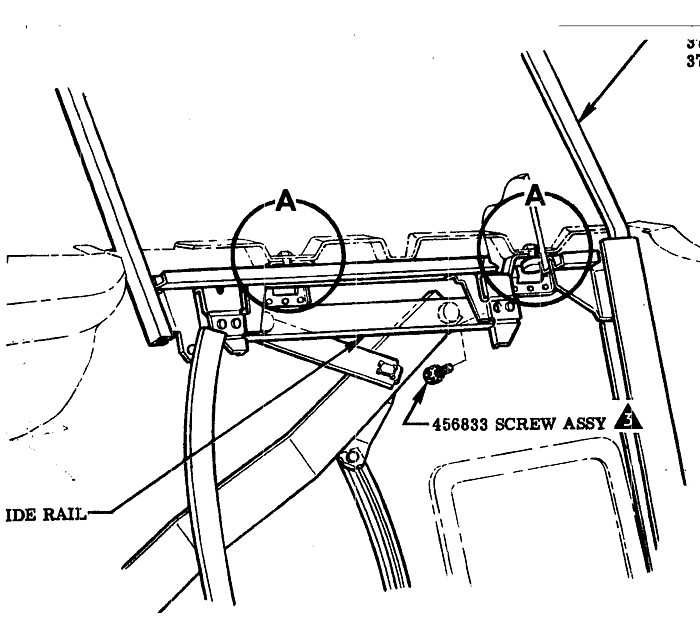
**********
07/1/2023
You’re probably sick of answering tach questions but I’ll ask you another one
anyway because I didn’t see a previous answer for this exact problem. I have a
62, 300hp. The tach started to stick really bad in different places and never
went back to zero. I took the tach out of the car, cleaned some black gunk out
of it with brake cleaner and oiled the bearings with 3 in 1 oil. I tested it on
my work bench and it seemed to work just fine. After I put it back in the car,
there were problems right away. The tach is dead at zero for about the first 10
minutes that I drive, then it comes to life and works fine. It also makes a
ticking noise.
Thanks,
Chuck
From:
Larry Pearson, SoCAl Chapter Advisor:
Chuck: The C 1 Corvette tachometer works exactly like a speedometer. The
difference is that the tachometer is calibrated to read twice shaft speed
(the distributor that drives it turns at half engine speed) and a
speedometer is calibrated to read 60 mph at 1000 rpm shaft speed.
The tachometer consists of two main parts. The first part is a die cast
housing contains a shaft that connects the drive cable to a bar magnet. The
shaft has two bronze bushings that are permanently lubricated with grease.
With lots of use these bushings wear out when the lubricant dries up. Years
ago, you simply purchased a new die cast assembly, but that serviceable part
was discontinued many years ago. Speedometer shops are usually able to take
the shaft out and repair the worn out bushings. Worn out bushings may be
the source of the ticking noise. Worn out bushings may allow the bar magnet
to contact the speed cup (discussed in the next paragraph). Bushing wear
can be determined by grasping the end of the shaft where the cable connects
to it and see if it moves up and down, indicating excess bushing wear.
There should be no movement.
The second part is an aluminum cup, called the Speed Cup, that mounts on a
separate shaft over the bar magnet. The spinning bar magnet induces a
torque into the speed cup, which is connected to a shaft that goes to the
pointer. This shaft has a coil spring attached to it in the middle that
controls the movement of the pointer and returns the pointer to zero when
the engine is turned off. There are lubrication points on each end of the
speed cup shaft and they may need lubrication. The 3-in-one oil could be
used to lubricate these areas. The fact that your pointer sticks at zero
when starting out indicates the possible need for lubrication at the front
end of this shaft. The tachometer is calibrated by increasing or decreasing
the strength of the magnetism in the bar magnet. This can only be done by a
speedometer repair shop.
If the main shaft needs lubrication,but is not worn out, here is what I do.
I drill a small hole in the top of the die casing just where the threads
end. This puts you in the middle between the two bushings. I then use a
hypodermic needle on a syringe and inject a small amount of heavy gear oil
into this opening. Rock the unit end to end to get the oil in contact with
the bushings. This normally fixes a problem with dry bushings, in my
experience. The presence of dry bushings is indicated by the cable breaking
when the bushings seize up. Or a howling noise, indicating dry bushings.
If this happens, disconnect the cable immediately or severe damage to the
pointer (with speedometers) or damage to the speed cup and shaft can result.
Last, if nothing works, it is time for a professional to rebuild your
tachometer. Corvette Central offers a rebuilding service.
Answering tech questions is what we do, and we love it. Keep the questions
coming! We want you to enjoy your C 1 Corvette to the maximum. That is
what SACC is here for.
Larry Pearson
**********
06/19/2023
On a 1959 power glide Corvette when put in
the park position it keeps popping out.
Is there a fix for this, the linkage looks to be ok.
Thank you
Steve
From:
Larry Pearson, SoCal Chapter Advisor:
Steve: Possibly the rubber shift lever boot is incorrect or incorrectly
installed or is too stiff. Take it loose from the console plate and see if
that fixes the problem. Some of the new service replacement shifter boots
are very soft and installing one of those could solve your problem.
Larry Pearson
**********
06/18/2023
I recently had a new soft top installed on my ’59. The frames are original and
were sandblasted and powder coated. The top fabric, etc. was sourced from Al
Knoch and the weatherstripping came from Corvette Central. When folded down,
the top is too thick for the lid to close. What can be done to alleviate this
problem?
Dave
From:
John Spencer, Red River Chapter Advisor:
This is a common problem. If you try to force the deck lid to close - you can
break the lid “don’t force it”. My only suggestion is to employ two restraining
straps to pull the top down. These came standard on earlier models
From:
Larry Pearson, SoCal Chapter Advisor:
Dave: The problem is that the fabric that Al Knoch uses to make today's
replacement Corvette convertible tops is MUCH thicker (I
estimate twice as thick) as was originally used by Chevrolet. The original
material was, literally, paper thin. As far as the appearance goes, the
top fabric is completely correct. The "fine grain" pattern in the vinyl and
the bindings are completely correct.
One of my 62's came with the original top fabric. When I folded it into the
top compartment, it literally fell into place. Because this car is a
"driver", when I replaced it I used a service replacement top kit I
purchased for $50 at a local car swap meet. The fabric pattern is the
incorrect "diamond point" pattern and it is thicker than the original
material but it works and it fairly easily folds into the top compartment,
but not as easily as the original top material did.
Then I purchased a 60 Corvette that already had a service replacement top
that needed replacement. So I went to Al Knoch and paid the price for a
white top with the proper date code embossed into the rear window (for $50
extra). I installed it myself with great difficulty (the pads he made at
the time are over one inch too short). When I folded it into the top
compartment, like you are experiencing, it wouldn't fit. So I pushed it
down as far as I could and slammed the cover down on it. That is all you
can do if you want to put the top down. The next problem happens when you
raise the top. It has deep seated wrinkles that don't easily go away. It
takes several days of very hot weather to take most of the wrinkles out.
The date stamp in the rear window is the next problem. Al Knoch cold
stamps the date into the rear window plastic. After a couple of years, the
window plastic has a "memory" and the $50 date code disappears. The
original date code was hot stamped into the window plastic and it is
permanent. I complained to Al about this, and he said to send the top back
to him and he would re-do it. Yeah, right!
For Al to fix the thickness problem, he would have to manufacture a thinner
material. Then the competition would point out that their material is
thicker and better. Very few people are alive today who
can recall how the original material performed. NCRS doesn't have a clue.
They should deduct for the wrong material. Al would then have to fix the
problem. This would be good for his business, because everyone would have
to purchase a new top.
My advice to you is to lodge a complaint with Al Knoch. Send him a copy of
my letter and scream at him. He knows the truth. Maybe if enough people
complain and NCRS gets its act together, he will fix it.
Larry Pearson
**********
06/16/2023
I have a 1960 doing a restomod. The rear end is housing is stock, stock axles,
stock leaf springs. How wide of a rim can I install on the rear end without
rubbing the inside? I have cragars for the fronts 15x4. I want cragars for the
rears? Thanks. J
From:
Michael Cappozio, Ohio Restorer:
J, with stock rear differential you can use a 7” wide rim with 4” backspacing
before any real worries. An 8” rim is pushing it. 225 tires are going to be
about the maximum width. A 235 can be used but with a good dip in the road, I.E.
a bump, pothole, etc., you risk hitting the wheel lip and cracking the quarter
panel at the bonding strip.
From:
Larry Pearson, SoCal Chapter Advisor:
J: The stock steel wheel for the C1 Corvettes is 15x5, not 15x4. I never
heard of a 15x4 wheel. Who would want it? The optional wheel was 15x5.5.
In my experience, the problem is not so much the wheel width as the tire
width. The problem is on the front. The wheel and tire may fit the front
fender just fine going straight, but turning into a driveway too fast and
too hard can result in the front tire contacting the fender lip and breaking
it. A short wide tire (aspect ratio of 60 or less) probably will not pose a
problem with fender breakage. I would not go with a wheel wider than 6
inches. Choose a tire that is proper for the wheel width you choose. Wide
tires on narrow wheels gets you nothing in performance. Make sure that the
wheel you choose doesn't have an offset different than stock. An offset
wheel will place undue stress on the small outboard front wheel bearing and
will result in premature bearing failure. If you don't have power steering,
wide tires make the car very difficult to steer.
Larry Pearson

From: Don Eckhart, Red River Chapter Advisor:
I believe ‘58 thru ‘60 are the same and I am running 17x7” with a 4”
backspace.
Don E.
From:
Verle Randolph, Red River Chapter VP:
I have run 15X7 wheels on my 57 for years with no problem. They need to have
the right backspace and I don't remember what that backspace is right now. I
do know that 1970 Camero 15X7 Rally wheels work with 215X15 tires and did
not rub. I ran with stock full cover hubcaps and no one could tell they were
Rally wheels. Very nice ride and much better handling.
Verle
**********
06/14/2023
Hi, my name is Mark I have a 57 Corvette and would like to know what are the
measurements of the front emblem between the hood and grill, and the cross flag
emblems in the cove? The front end is aftermarket, so I do not have existing
holes to check for repairs or evidence of holes on the inside.
Thank you for your expertise.
Mark
From:
John Spencer, Red River Chapter Advisor:
The nose emblem (center) on my 54 (like a 57) is 3 3/4 in above the edge of
the fiberglass/grill interface.
The Cross Flags (center) is 10 in back from the wheel opening along a line 6
in above and parallel to the bottom cove trim.
Note: Is your car a F.I. ? The Cross flags were only on the F.I. cars I
believe.
From:
Verle Randolph, Red River Chapter VP:
My unrestored 57:
Front emblem bottom edge is 3 inches above the chrome trim surround of the
grill opening.
The crossed flag center is 6 inches back from wheel well edge and 6 inches
above the lower cove trim.
Verle
**********
05/25/2023
Hello,
I am trying to locate a PROPER horn contact ring for my 57.
The repro ones the vendors have, do not work as they will not mate
with an OEM horn button (760805)).
The black spring steel retaining tabs are too short to accept the recessed
cavities cast into the horn ring. I believe the segmented mounting ring on
the back of the horn button could be machined down enough to allow
the dimples to engage. I don’t want to do this to my pristine OEM
button.
Any information or education or part supplier would be greatly appreciated.
I have attached a pic of a proper ring above, (forgive the quality) the
difference vis a vis the
new reproductions is obvious.
Thank You!
Keith
From:
Larry Pearson, SoCal Chapter Advisor:
Keith: Where did you get this improper reproduction horn contact? In my
experience, Corvette Central sells the right stuff. And if it is not right,
they will make it right. Their part number is 561122, and is is called Horn
Contact, 1956-1962. The cost in their latest catalog is $26.95. I am
quoting out of their latest hard copy catalog. You can go to their web site
catalog and should be able to get a close up picture of what they are
selling. Their web site is:
www.corvettecentral.com.
Larry Pearson
**********
05/22/2023
RE: 1957 Corvette
I am looking for hole location & diameter for the antenna on my 1957
Corvette. The car has a hole that was in the wrong spot. Car is now 100%
done. Need to drill a hole in the left rear febder. But don't know the
location. Perhaps I can get a measurement forn the chome of the taillight
to the edge of the hole, and of course the diameter.
Thanks so much.
Bill
From:
John Spencer, Red River Chapter Advisor:
The antenna hole is approximately 4" in front of the tail light . The hole dia
is 11/16in. See attached illustration. NOTE: The antenna mounts (bottom) on the
inner wheel well - check to see if those mounting holes are still there. Align
the fender hole accordingly.
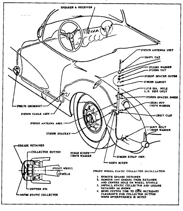
**********
05/11/2023
Hello,
Is there schematics, drawings, or videos that are available to aid in
disassembly and reassemble a 1959 corvette hard top? Someone has done it that
would be willing to talk to me and answer a couple of questions?
Larry
From:
Bill Huffman, Michigan Chapter President:
Larry,
As a longtime owner
of several C-1s with hardtops, my best advice is to talk to the experts
before damaging some very expensive parts to replace.
Both of these firms
do tech demonstrations at major shows such as Funfest at Effingham, IL, or
Bloomington 500 coming up later this month in Bloomington, IL.
Experts love to talk
at shows for free, their professional services cost money.
Good Luck with your
hardtop,
Bill Huffman, Pres.
Michigan Chapter SACC
**********
05/08/2023
Hello,
I have just installed a newly rebuilt differential in my 1958 Corvette and I
can't find what the torque specifications are for the ten differential nuts and
the axle flange bolts. I am hoping the experts can help me out with these
specifications.
Thank you,
Michael
From:
John Spencer,
Red River Chapter Advisor:
I did not find torque specs on the Differential cover bolts - but the spec on
the axle companion flange is 150 - 190 Ft Lbs
From:
Larry Pearson, SoCal Chapter Advisor:
Michael: The answers to your question are found in the Chevrolet passenger
car shop manuals. The nuts attaching the Differential Carrier to the 10
axle housing studs are to be torqued to 35-45 ft. lbs. Use a slide hammer,
as necessary, to install the axles into the axle housing until the outer
race of the bearing is seated against the shoulder in the axle housing. The
four nuts and split lock washers that attach the bearing retainer studs to
the axle housing should be "tightened securely". No torque number is
given. The five wheel lug nuts should be tightened in a cross sequence to
45-65 ft. lbs. Most tire shops are now using a torque wrench to tighten the
lug nuts instead of an impact wrench which, in my opinion, over-tightened
them. They do use an impact wrench to remove the lug nuts. It speeds
things up.
Larry Pearson
From:
Verle Randolph, Red River Chapter Advisor:
The differential cover bolts are not under stress so they don't require a
great deal of torque. I use a socket and ratchet to tighten them, usually a
quarter inch drive with a short ratchet handle, until they are firmly set
against the cover.
Verle
**********
04/26/2023
I have a 1960 Corvette with solid lifters. My research indicates the solid
lifter cars came with a different pressure plate than those with hydraulic
lifters. Is the originally correct pressure plate available, and or is it
still necessary ?
Also if I do use a diaphragm style pressure plate does the gorilla spring work
the same?
Thanks,
Bob
From:
Larry Pearson, SoCal Chapter Advisor:
Bob: I own a 230 hp all original 1960 Corvette and it came with a Borg and
Beck (B&B) style (3 arm) pressure plate, not a Diaphragm pressure plate. It
even still has the original clutch disk in it. At the time, it was believed
that the B&B type pressure plate could handle more horsepower, so all C1's
came with a B&B style pressure plate, no matter what the horsepower. Later
Mid Year Corvettes came with a diaphragm style pressure plate. Maybe they
re-designed it to handle high horsepower, I don't know.
If you use a diaphragm style Pressure Plate, the large assist spring cannot
be used. If you try to use it, the clutch pedal will go to the floorboard
and stay there. Diaphragm pressure plates offer a much lighter clutch pedal
effort and the large assist spring is not needed. Instead they used a much
lighter spring to prevent rattles, I am told.
I have not bought a pressure plate in many years, so I don't know what is
available. Try to avoid rebuilt units, but maybe that is all you can get.
The last new pressure plate that I bought was made by Borg Warner in
Brazil. It was a piece of junk. It disintegrated in the car while driving
on surface streets. I ended up reinstalling the old made in USA unit.
This was over 15 years ago.
Larry Pearson
From:
Verle Randolph, Red River Chapter VP:
Borg & Beck pressure plates are available but I don't know if they are any
good.
Back in the 1950s and 60s Borg and Beck style pressure plates were the go to
for high performance.
Now days diaphragm pressure plates will work ok for our old cars.
I have had a diaphragm in my 57 for the last 20 some years and 40 some
thousand miles with no problem but I don't race it.
Verle
**********
04/10/2023
Hello,
I am trying to remove the axles in my 1958 Corvette to change my differential.
I have removed the rear brake hubs and brakes and the four nuts holding the
retainer on the inside of the brake baking plate. Using my slide hammer which
has two fingers or jaws I am unable to pull the axle, even after I repeatedly
sprayed the retainer and studs with a nut buster. I'm looking for other
suggestions on how to get them free after sixty-five years.
Thank you,
Michael
From:
Verle Randolph, Red River Chapter VP:
Some ideas:
Use a chain to FIRMLY secure the axle to the frame. There is give in the
springs that will reduce the slide hammer efforts
Try slide hammer
Try heavier slide hammer. Add weight to you slide hammer
Might whack the center of the axle with a heavy brass hammer . I know, the
wrong direction.
As a last resort heat the axle housing some, NOT red hot, then slide hammer.
I made a bigger/heavier slide hammer with a piece of all thread, and a pipe.
Longer throw (36" all thread), welded "things" to the pipe for weight.
Perseverance is necessary. The first time I removed axles from my 57 it took
a long time, lots of effort, trying multiple ideas.
Verle
**********
04/7/2023
Hi, do you have or do you know where I can get a template for the location of
the 1960 Corvette cove crossed flags?Just acquired a 60, and it doesnt have the
flags! I must have them ! LOL
thanks a bunch! Jerry
From:
Michael Cappozio, Ohio Designate:
Not sure if there’s a template, I may be wrong, but measurement is 5 3/8” up
from the lower stainless trim and 5” back from wheel lip to the first hole.
Measure your emblem to get distance for second hole as you emblems tend to be
inconsistent in that measurement and you end up having to file hole bigger to
fit.
From:
Bill Huffman Michigan Chapter President:
Jerry,
Remove the Dr & Pass
side splash shields located rearward of the front wheels.
Check the backside of
the cove panels where you should find the body filler they used to fill the
original mounting holes. Carefully push the body filler outward with a small
nail or drill bit to reopen the holes.
Good luck,
Bill Huffman, Pres.
Michigan Chapter SACC
From:
Larry Pearson, SoCal Chapter Advisor:
Bill's excellent answer assumes that the emblems were removed and the holes
were filled. It is possible that the front clip or that body panel has been
replaced with an aftermarket part on your car and the holes were never
there. If so, you need to find an original 1958-60 car and and make a paper
template from it. There are no templates on the market that I am aware of,
and the Corvette Assembly Instruction Manual (AIM) for your car does not
give dimensions.
Larry Pearson
From:
John Spencer, Red River Chapter Advisor:
Center of flags is on a line 3/8 in below the center spear, 6 1/4 in from the
edge of the cove. See photo attached.
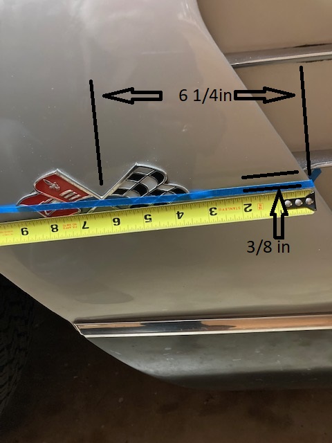
**********
03/14/2023
Hello,
I have a 62 hardtop question. I would like to replace the hardtop header bar
weatherstripping. The rubber is cracked, hard and brittle. I have removed some
of the rubber. It seems that GM glued the rubber on, in addition to using the
P-Clips and rivets. Is there an easy way to get this rubber off? Do I need to
remove the header bar from the roof to do this job or can I replace the weather
stripping with the header bar on the roof?
Thanks,
Chuck
From:
John Spencer, Red River Chapter Advisor:
I
have simply refurbished C1 tops by refreshing their weatherstripping and I have
totally disassembled them. You do not need to remove the header bar to replace
the header weatherstripping. You have to simply drill out the rivets, then
scrape the weatherstrip off (or use a glue release agent). When replacing the
weatherstripping - if you do not have push rivets - you can tap the holes and
use shallow head machine screws.
**********
03/04/2023
Does anyone have a diagram showing the correct location for the Under Dash
Support Rods. Needed for my 1961 C1.
I am completing a 7 year frame off and have no recollection of their placement.
Thank you,
Archie
From:
Larry Pearon, SoCal Chapter Advisor:
Archie: I am not familiar with the term "under Dash Support Rods". However
the answer to your question should be given in the 1961 Assembly Instruction
Manual (AIM). The AIM for your 1961 Corvette is a collection of engineering
drawings that instructed the assembly line on how to build your car. The
AIM for your car is available in the form of a reprint from all of the major
Corvette restoration parts suppliers. I recommend Corvette Central,
http://www.corvettecentral.com.
Larry Pearson
From:
John Spencer, Red River Chapter Advisor:
SEE ATTACHED EXPLOSION OF DASH - FROM CORVETTE ASSEMBLY MANUAL
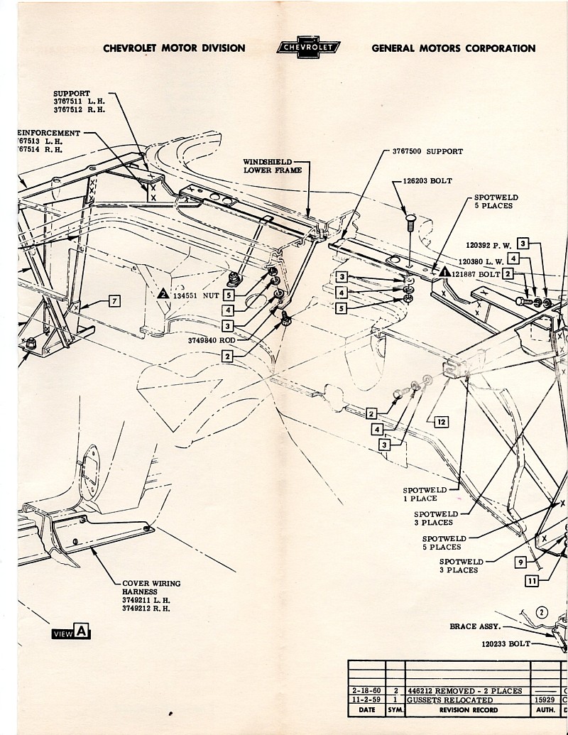
**********
02/28/2023
1960 corvette automatic trans lockout relay 904
Does any rebuild this
relay.
I have power going in activating the point but not 12 volts going out to the
starter.
Thanks
Steve
From:
Bill Huffman, Michigan Chapter President:
Steve,
If you are looking
for the 1960 Neutral Safety Switch, the switch is sold new, made off GM
tooling by Paragon Reproductions.
It is their P/N
13287, and all the linkage and brackets are also available.
Bill Huffman, Pres.
Michigan Chapter SACC
**********
01/13/2023
Looking for help,
Just purchased a 1959 Corvette that had a restoration started in 1999, then
the owner lost interest after 1 year. It sat for
19 years covered in his barn before I purchased it, know I'm in process of
finishing the restoration and am trying to find the correct amount of pads
and there placement on the frame. Is this something you can supply me info /
pictures of? I've attached a pic of the car how I received it.
From:
John Spencer, Red River Chapter Advisor:Get
a copy of Chevrolet's service manual "ST-12" it is a must for anyone restoring
an early Corvette. Your body shims (8) are shown in Fig-103, Pg.1-49
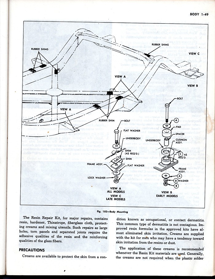
From:
Larry Pearson, SoCal Chapter Advisor:
Ron: To see the location of the shims (not pads) that were attached to the
top of your frame when your Corvette was assembled at the factory, you need
to acquire a copy of the 1959 Corvette Assembly Manual (AIM), which can be
purchased from all the major Corvette parts and accessories dealers. The
AIM contains a complete set of engineering drawings that illustrate how the
1959 Corvette was assembled at the factory. Section 1, Sheet 1.00 shows the
locations of the shims, which consist of a black rectangular fiber shim,
about 1/4 inch thick, and a rectangular steel shim, about 1/16 inch thick.
The number of the steel shims that were placed on top of the fiber shim was
determined at the factory, and no procedure is given on how the factory
determined how many steel shims were needed. The correct number of shims
was attached to the top of the frame at each location using 1/2 inch masking
tape. This was done prior to the body being set on the frame and bolted in
place.
The picture that you show of your car has the body on the frame, and I
assume that the body is bolted to the frame with the original shims in
place. If so, you do not need to determine how many shims are needed. They
are already there. The black fiber shims do not deteriorate. They are not
made of rubber, like was used on the 1963 and later Corvettes, and which can
rot. If you need shims, contact Corvette Central.
Larry Pearson
From:
Verle Randolph, REd River Chapter VP:
Frame shims are often changed to adjust door gaps, front and rear.
Don't be surprised if your door gaps are not good and you have to add shims.
Verle
**********
01/29/2023
I purchased a pair of roller-bearings a few years back for my 62. I have
been trying for 3 years to make these work with no luck. The bearing seals
jam against the inner races causing the seals to rotate. and fall out. The
company says to only install the seals halfway which does not work. The
seals fall out backing out of the garage. The guys at the company say they
use them frequently and are no help. I have used 5 different brands of
seals, none of which clear the lip sticking out of the inner races. I have
received numerous suggestions all of which involve modifying the hubs to
make a Chinese bearing work that is obviously made for some other
application , not automotive. My car has Moog replacement hubs, last
available in the 60's and much heavier than the GM hubs. I purchased a pair
of OEM hubs (another suggestion) but the same problems exist. The bearings
simply do not fit.
Has anyone made these roller bearings or any other for that matter, work
on non-trailer queen cars? These have been far more trouble than the
ball bearings were in the past 47 years I have owned the car.
Thanks,
Gary
From:
Larry Pearson, SoCal Chapter Advisor:
Gary: Thank you for sharing your experiences with front roller wheel
bearings on your C1 with sacctech.
I currently have 13 cars and have owned 5 C1's over the years and currently
own a 60, two 62 Corvettes, a 56 Chevy, a 51 and a 53 Oldsmobile and a 55
Cadillac. All of these cars have ball bearing wheel bearings. I have never
had a ball bearing wheel bearing failure on any car that I have maintained.
Over the years, I purchased a 51 Oldsmobile, the 56 Chevy, and a 62 Corvette
that had bad wheel ball bearings, usually one or two for the four, when I
acquired them. It is my opinion that ball bearing wheel bearings will last
the life of the car if properly maintained. Over a ten
year period, I used to slalom race (SCCA SOLO 2) one of my 62's and never
had a wheel bearing failure. In my experience, roller bearings are much
more tolerant of maintenance neglect, and maybe that is what you are looking
for. The early cars require very frequent chassis lubrication, every
1000-2000 miles. Today's
cars are virtually maintenance free, and owners are used to doing nothing
other than changing the oil. You can't do that with a C1.
In my experience, ball wheel bearings are much easier to clean and properly
pack with grease than roller bearings, because the inner race can be
removed, giving full access to the balls in the cage. The inner race is
permanently attached to the rollers in roller bearings, and it is very
difficult for me to properly clean and re-pack them. But I have never
experienced a roller wheel bearing failure.
My advice to you is to go back to ball bearing wheel bearings. Use an
original hub.
Larry Pearson
**********
01/10/2023
I am a new owner of a 1960 Corvette. A very nice mostly numbers
matching car. The previous owner put masking tape on the wheel nubs to
help keep the original hub caps on. What is the correct way to make them
go on tight?
Thanks Bob
 From:
Don Brittin, Central Regional Representative:
From:
Don Brittin, Central Regional Representative:
1st) check if the wheels are correct.
Must have the 3 small retainer bumps in the inside of the outer part of the
wheel.
The tape may not hurt, but is only useful to tighten the fit a
bit, but should not be necessary.
Donald J Brittin
From:
Larry Pearson, SoCal Chapter Advisor:
Reproduction 56-62 wheel covers have a reputation for being
loose. I have never experienced a factory original wheel cover
from these years for being in the slightest bit loose. If
masking tape on the nubs works for you, use it. However, there
is another problem with loose wheel covers, and that is the
wheel cover will move in such a way as to put pressure on the
rubber valve stem, possibly damaging it or breaking it off. If
this happens, the only solution is to install metal valve stems.
You should keep your eye out for a set of original wheel
covers. You should be able to purchase a decent set for around
$400. Many C-1 Corvette owners are installing after market
wheels that don't use wheel covers. When you encounter one of
these cars, you should ask the owner if he has the original
wheel covers. He will probably never use them and likely will
be happy to sell them to you. The 1959-62 wheel covers have the
slots around the perimeter and are all the same. The 56-58
Corvette wheel covers did not have slots around the perimeter.
Larry Pearson
**********
01/06/2023
I want to verify and take pics of my vin number, on the frame. I plan on cutting
a hole in the floor. Are there measurements I could use? I've tried the mirror
and light under the car, but to no avail. Jim
From:
Bill Huffman, Michigan Chapter President:
Jim,
Before you cut a hole
in your car floor on the outboard of the driver seat, about even with your
hip joint, directly above the frame rail, I have three questions.
1) Have you tried
taking a picture with your i-phone, with & w/o flash?
The I-phone
should fit even if you have to remove the cover
2) Have you tried
transferring the frame number to a piece of paper by rubbing a # 2
pencil lead lightly across it in that area?
3) Is there some
compelling reason why you need to verify that the frame number matches
the VIN tag, or are you just curious?
Why not try a camera
on a cable to your i-phone as a solution.
Beats cutting
fiberglass if you don't need to.
Bill Huffman, Pres.
Michigan Chapter SACC
From:
Larry Pearson, SoCal Chapter Advisor:
Jim: I have three C 1's and have never needed to do this. Do not
cut a hole in the floor. I have seen one frame with the body removed.
The characters are quite large, over 1/4 inch high, and were stamped
into the frame top with such force that the frame metal deformed,
creating a depression that will allow water and debris to collect,
promoting rust where the stamping is. If your frame has a lot of rust,
the stamping may not be readable, no matter what.
The stamping is located under the driver's seat. The fiberglass floor
pan is somewhat flexible in this area. I suggest that you make up two
wedges out of wood and force them between the frame and the floor pan to
give you more room to clean off the frame top and view the area with a
mirror. You may have to use a rust removing chemical based on
phosphoric acid, like Navel Jelly, to clean the rust off for better
viewing. If you are successful with this, apply grease to the cleaned
area to prevent future rusting.
Larry Pearson
From:
John Spencer, Red River Chapter Advisor:
What year is your car? What is the condition of the car (Body-interior
intact or disassembled / engine intact or removed - steering column in place
or removed). The location of the VIN stamp is not exact, and there are
braces running under the floorboard where the stamp is located. I don't
recommend cutting the floor. You don't have to totally remove the body -
you can remove all mounting bolts and lift the body on one side (driver's).
**********
01/06/2023
I have a 1960 Corvette that my Dad has given to me for restoration.
Unfortunately the car was disassembled 20+ years ago and I was not involved in
the disassembly. I have purchased several restoration books but haven’t seen the
detail I’m looking for yet. What is the best reference books hopefully with
pictures that show details of how parts are assembled. Thansk
Thanks,
Kris
From:
Bill Huffman, Michigan Chapter President:
Kris,
I have disassembled
and reassembled several C-1s completely over the years.
I have found the best
illustrations for my 1960s in the 1960 GM Assembly Manual.
It has GM P/Ns for
components and fasteners plus torque & lube information.
According to a
chapter member who was a production line engineer in St Louis starting in
1959, if an installation takes you more than 9 minutes, your assembly
process is incorrect. That was production station to station line speed.
The assembly manual and the1953-1962 Corvette Servicing Guide ST-12, both
available on-line, should answer 99 % of your questions.
The Corvette Servicing Guide ST-12 can be found at:
chevy.oldcarmanualproject.com/shop/5362csg/
Bill Huffman, Pres.
Michigan Chapter SACC
From:
Larry Pearson, SoCal Chapter Advisor:
Kris: You need to acquire a copy of the 1960 Corvette Assembly Instruction
Manual (AIM). This manual is a collection of official engineering drawings
prepared by Chevrolet Motor Division that details the complete assembly of
the 1960 Corvette as was done at the Flint, Michigan Corvette plant. It
shows every part used to make the 1960 Corvette, including screws, bolts,
nuts, washers, rivets, sealants, and adhesives. These Assembly Manuals are
available as reprints from all the major Corvette parts suppliers. Also,
you should obtain a copy of Corvette Servicing Guide,Chevrolet publication
ST-12. This is the only official Chevrolet shop manual for the 1953-62
Corvettes. This will help you service your car once you get it assembled.
Larry Pearson
From:
John Spencer, Red River Chapter Advisor:
Kris - I agree with Larry a 1960 assembly manual will be invaluable for your
project as well as the service manual ST-12. In addition, log into Paragon
Corvette and request a copy of their parts catalog. In addition to parts you
may need their catalog contains numerous illustrations / assembly breakdowns
that will help you assemble your Corvette Kit properly. Good Luck
**********
01/02/23
Hi guys - my 1954 has been fully restored except for top. My quandary is what color because the existing top is black but the frame is tan. As I understand, 1954 tops were tan, but I also understand that supply issues resulted in some issues. How can I find out which color top I need? Attached is build plate. I’ve owned my Corvette since 1967, with frame off restoration ending in 2019 (just before pandemic).

Thanks, mike
From:
John Spencer, Red River Chapter Advisor: My
54 top is tan. There are a lot of variations undocumented - but - all the tech
references I have spec the 54 top to be tan. Also - all reference docs report
the tops to match the frames. Since your frame is tan I suspect your original
top was tan. All this being said - unless you are going for NCRS judging - it’s
your car - put the color top on you want.
**********
12/20/2022
My 1956 radiator core support had a large hole cut in the bottom
of it in line with the radiator drain. Thinking that it looked
ugly, I had a welder remove the drain hole section from a later
solid axle core support and weld it into my 1956 core support.
I'm thinking that when I did this several years ago, I should
have done more research. I am now thinking from what I see in
the assembly manual that the 1956 core support may not have had
a drain hole in the bottom. Is that correct?
Thank you for all of your help,
Michael
From:
John Spencer, Red River Chaprter Advisor:
Attached is a photo of a core support - supposedly for 53 thru 57 - you can see
a drain port where the radiator pitcock is located. My 54 has the same feature
- but i can't swear that a 56 does. I will contact some 56 owners and get a
more definitive answer.
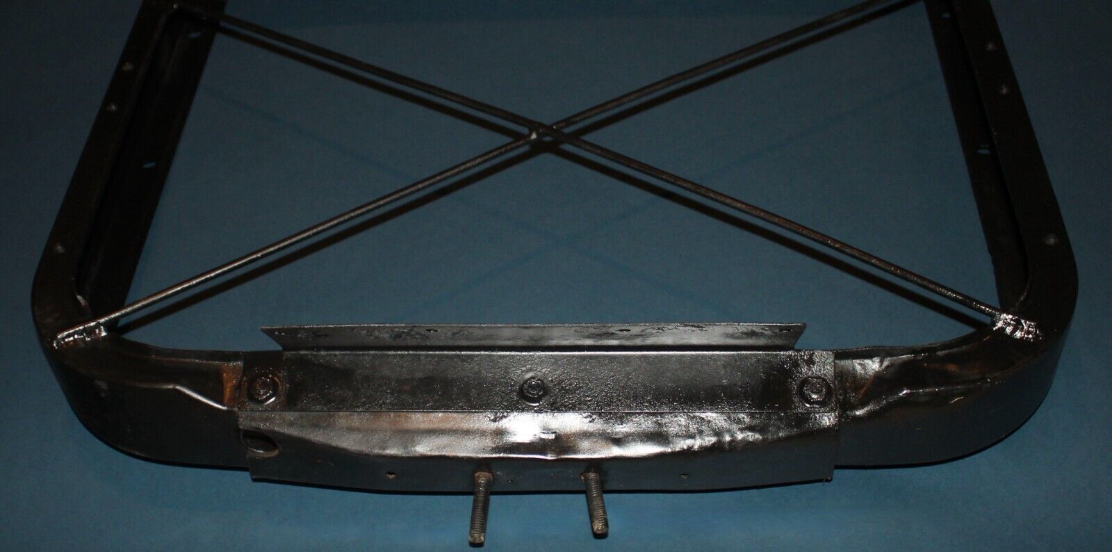
From:
Bill Huffman, Michigan Chapter Advisor:
Michael,
I think that this
e-bay item will answer your question regarding what your core support should
look like. It has pictures of an NOS core assembly.
**********
12/19/2022
Hello- My name is Kyle and I have a 61 fuelie corvette. We just finished
putting it back together and after it warms up and the choke comes off it idles
too low and putters and sometimes stalls out. Do you guys know of any ways to
get the idle up after it warms up?
Thanks!
Kyle
From:
Larry Pearson, SoCal Chapter Advisor:
Kyle: I assume that you have a 7017320 unit on your car. This unit and all
previous units did not have a choke. The 7017355 and 360 units introduced
on the 1962 Corvette had a true electrically heated choke. The 320 unit had
a Cold Enrichment Assembly, which looks like a choke but is not a choke.
However, it does control the fast idle cam on the top of the Air Meter. It
has an internal electric heating element that, through a link to the fast
idle cam, moves the fast idle cam. When fully warmed up, the fast idle cam
no longer controls the idle speed. At that point, it is controlled by the
Idle Speed Screw. That is the large spring loaded screw on the side of the
Air Meter. You need to procure a copy of the Corvette Servicing Guide,
Chevrolet publication ST-12 and go to page 6M-7 and review the IDLE SPEED
AND FUEL section on that page before adjusting this screw. ST-12 is
available as a reprint from all Corvette supply sources.
If your unit idled just fine and suddenly lost its hot idle, the problem
could be with the Air Meter itself, and adjusting the Idle Speed Screw is
not the proper solution. In that case, remove the air meter from the plenum
and inspect the area in front of the brass throttle valve. There are some
small openings in the aluminum casting that can get plugged up with the
brown sludge that coats the inside of the plenum after a lot of use. These
small slots provide a small vacuum signal to the Fuel Meter to cause it to
provide fuel at idle. The Idle Speed Screw adjusts the amount of this
vacuum signal that goes to the Fuel Meter. If this us the problem, use
lacquer thinner and a Q-tip to carefully remove the sludge blocking the
openings. Be careful to not damage the shape of the openings.
Larry Pearson
**********
12/11/2022
I am refreshing the motor in my 1956 corvette vin #E56S002002. I saw where early
56 engines were painted red. My biuld date is April
17 so
what color is my engine supposed to be? thank you, Samuel
From:
Larry Pearson, SoCal Chapter Advisor:
Samuel: The 1956 engines were all painted red, including the sedans. I own
an all-original 1956 Bel Air sedan and the engine is painted red. This
engine has the stamped steel rocker arm covers and the word Chevrolet is
highlighted in silver paint. They sell red paint for the 56 engines and the
color is correct.
Larry Pearson
**********
12/10/2022
In March
1954 a
1953 Corvette was parked in a parking lot across the street from the hotel that
the owner lived in. His name was A. J. Noll and he was the owner of the local
General Motors dealership here in little old Macon, Missouri, population 4,000.
Me being a nosey senior in highschool I went over to check it out. Well would't
you know the keys were in it. So what do yoy think I did, yep, I got in , got
it started and put it in gear, then I heard this loud crash, that darn Corvette
jumped right into that solid brick wall in front of it. I shut the key off and
jumped out and went home. Someone saw me and ratted me out. I have the repair
service sheet from the shop and also a copy of the payed bill. In March of 1954
no one in Macon knew anything about fiberglass, the shop foreman made some phone
calls and was told to use wood putty to repair the damage, so that means someone
out there who thinks he has a pristine Corvette could be in for a surprize. I
wold like to know if you have the knowledge to track down that car, that is if's
it's still around. I have always wondered how a small dealer like A. J. Noll
living in Macon, Missouri with a population 4,000, could you be of any help or
could you direct me to someone who could help. Thanks
George
From:
Bill Huffman, Michigan Chapter President:
George,
Without the VIN
number you have little or no hope in finding this automobile.
A 1953 Corvette VIN
number would be E53F001 _ _ _.
The last three digits
will be 001 thru 300.
The repair service
sheet & the copy of the paid bill should both contain the VIN number of the
vehicle you wrecked,
SACC Member John
Hutchins maintained a 53-55 Corvette registry until about 2010 when it was
taken over by Brett White.
Hemmings Magazine
also has a 53-55 Corvette registry.
Good luck finding
your needle in that haystack.
Bill Huffman, Pres.
Michigan Chapter SACC

From: Bruce Fuhrman, Past Club Secretary: I suggest that you start
with A.J. Noll and see what he delivered (Macon, MO) to in June
1953. Of he is dead, try a deferent dealer. If all fails, try '53-'55
registry. See what was delivered in"53 to Macon, MO. There was only 300
delivered!
You said that I have the "repair service" agreement. Is the S/N on it? They
used the block #.
Cheers.
Bruce Fuhrman
**********
12/08/2022
Hi, can someone help for support, I’m looking for.
56-62 corvette Center Floor Support - LEFT – Fiberglass
56-62 corvette inner Fiberglass rocker panel - Press Molded –
LEFT
Thanks Fred
From:
Bill Huffman, Michigan Chapter President:
Check out this
Corvette Central link
If you don't find it
there, contact Paragon Corvette Vintage at (800) 882-4688.
They sell original
used fiberglass panels from their in-house salvage stock.
Send them a picture
of your broken parts needing replacement or the panels around the part you
need but don't have.
Good luck in your
search.
Bill Huffman, Pres.
Michigan Chapter SACC
**********
1956 Soft top.
The weatherstrip is held / clamped into position with the
retainers and screws which attach to the “t nuts” in the header bar. Perhaps
there is another method of retaining this weatherstrip onto the header that I am
not aware of? The terminologies on the pics certainly imply some type of
fastening is used to retain the weatherstrip into position.
From:
Larry Pearson, SoCal Chapter Advisor:
Kim: I have installed several tops on 1959-62 Corvettes, but not on a
1956. I was not aware that these T-nuts were a serviceable part. They
always were in the header and could be re-used. You need one of these
T-nuts for every slot in the weatherstrip retainer. The retainer became a
single long part on the later Corvettes. The retainer also holds the top
fabric in place. As I recall, there is a tacking strip on each end of the
header to retain the ends of the top fabric.
Larry Pearson
**********
Hi, wondering when top flight inspections are done to a 1962 corvette are frame
vin #s checked to see if they match tag?
Dale
From:
Verle Randolph, Red River Chapter VP:
No NCRS judging sessions look for frame stamped VIN numbers.
All NCRS flight judging are done with the car setting on the ground.
Verle
**********
11/3/2022
I put a disc brake conversion on my 59 some 20 years ago. Just recently I
noticed that my right front caliper was dragging. Since the flex lines were
part of the kit, I replaced them with stainless steel flex lines. This did not
resolve the dragging issue, so now my question.
Current brakes conversions
still use the same single piston caliper but none of the supply houses sell
individual calipers nor do they indicate what type of GM caliper is used. They
appear to resemble the caliper of a 68 Camaro but I can’t find any literature
that will definitely confirm this. I am sure that since these brake conversions
have been on the market so long someone must have had to replace parts for them.
So does any tech adviser know what brake caliper is used on the conversion
kits?
Tnx
Paul
From:
Larry Pearson, SoCal Chapter Advisor:
Paul: All disc brake pads "drag" on the rotors, because disc brake systems
have no mechanism to lift the pads off the rotors when the brake pedal is
released like drum brake systems have with their brake shoes. Are you
saying that your right front caliper does not release its pressure on the
pads when the brake pedal is released, resulting in the car pulling to the
right all the time? Some times the flexible rubber hose to a brake cylinder
or caliper develops a problem where it blocks the line pressure from
releasing when the brake pedal is released. But you say that you replaced
the flexible lines to your calipers, and the problem persists. The only
thing left is the caliper itself. I have never heard of a disc brake
caliper behaving like this. However, if a caliper leaks brake fluid on its
pad, the coefficient of friction on the pad changes and the pad will grab
when the brakes are applied. Is this the problem you are having? If so,
you need to rebuild or replace the leaking caliper so it does not leak and
replace the pads on both sides so they are the same.
I always advise people replacing drum brakes on their cars with a disk brake
system to find out who made the calipers and what pads are needed when they
have to be replaced. I have heard that some disk brake conversions use Ford
Pinto calipers and pads on the front. Where did you buy your disc brake
system 20 years ago? Did you install it yourself?
Larry Pearson
From: Don Brittin, Central Regional Representative:
Paul, Corvette Central uses the Camaro front disc assembly. CC sent
me two left front calipers. I just went to the local Chevy dealer
got the exact replacement for the right side. The set up uses dual
master cylinders instead of the single circuit that was stock. You
MUST have a really good proportioning valve to balance the brake
pressure to the calipers.
Likely this is an adjustment issue.
Don
**********
10/31/2022
My car was assembled on on
April 18, 1960. Car 06443.
What should the stencil date be on the frame. Judging manual really does not
mention it.
Thank you
Rick
From:
Larry Pearson, SoCal Chapter Advisor:
Rick: Your frame was manufactured by AO Smith, dip painted with gloss
black asphalt based paint and stenciled in red with the AO Smith house
part number 707190-XX and the date of manufacture in another line under
this part number. The "XX" is the production batch number. The first
1953 batch number started out with nothing or -1. A friend of mine's 55
is -5. My late 62 is -52. I own an all original un-restored 1960,
#7575, but the car came from New Jersey and the stencil is completely
gone, replaced with surface rust. The stencil appears upside down on
the frame under the driver's seat. They used a paint brush to slop the
red paint onto the stencil. There can be runs in the red paint.
I am surprised that NCRS does not have the information on this for you.
They obsess about everything else. Contact the NCRS Team Leader for
1960 and see if he can help you. Corvette Central sells some stencils
for the 63-67 Corvettes, but nothing for C1's. I had to make the
stencil for my 1962 using a stencil kit from a stationary store. I did
this when I restored my 1962 back in 1974. before anyone knew, or cared,
anything about this stencil. Fortunately, the original stencil marking
was still readable.
Larry Pearson
**********
10/30/2022
Tech, I have a 1959 vette (member #2448) and am looking for someone
who might have a dvd I could rent or borrow to look at the
installation of the new top that I need. Thanks for any help. Craig
From:
Larry Pearson, SoCal Chapter Advisor:
Craig: Contact Al Knoch Interiors at
http://www.alknochinteriors.com or
1.800.880.8080. They manufacture a convertible top and pads for your
Corvette. They also sell a video that will show you how to install the top
and pads. Installing a convertible top on your top frame is not a simple
matter, however, and I suggest that you have a professional do the
installation. You will likely encounter problems with your top frame that
you will not be able to fix without help.
Larry Pearson
**********
0916/2022
I did a Frame Off Restoration on my 62 Corvette. Everything was fine. Then
one evening I turned on my Headlights & noticed I Nad NO Dash Lights. I
checked Fuses. Replaced Headlight Switch.
Nothing. I can't figure it out. If someone can help me. That would be
great. Thanks
From:
Bill Huffman, Michigan Chapter Advisor:
The
headlight switch knob & shaft has three positions when pulled:
In) All
lights OFF,
Mid)
parking & taillights ON,
Out)
headlights & taillights ON.
The
headlight switch knob & shaft also has three positions when rotated:
Full CCW-
courtesy light ON regardless of pull position,
First
detent CW- Courtesy light OFF but dash & clock lights ON if in Mid or Out
position,
Turning
the knob further CW, it is a dimmer switch for the dash & clock lights that
range from bright to Off as it rotates CW to the last detent or stop
position.
If this doesn't fix your
issue, look for a broken or disconnected wire in the dash & clock light
circuit.
Regards,
Bill
Huffman, Pres.
Michigan
Chapter SACC
From:
John Spencer, Red River Chapter Advisor: Dash lights are powered from the
headlight switch. Simply turning on the headlights will not power the dash
lights unless the light switch knob is turned. The light switch has a rheostat
to brighten / dim the dash lights as you turn (twist) the light switch knob.
Twist the knob ( clockwise and counterclockwise) one direction will exhibit a
click at the end of its travel - this is the full bright position. If you still
have no dash lights - test the feed off the light switch for 12V. If no voltage
pull your light switch and test contacts in the various switch positions
**********
09/15/2022
I opened up the fuel filter bowl to clean out the bowl and when I reinstalled
it and started the engine the bowl fill completely to the top. See picture.
This is not typical of how it was before. In the past the fuel alway seemed to
be below the bronze filter.
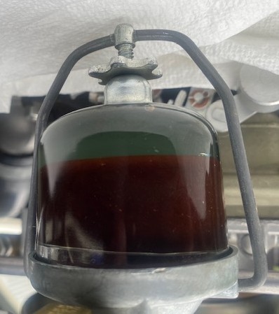
From:
Larry Pearson, SoCal Chapter Advisor:
Eugene: The GF 124 filter element you show is not made of bronze. It is a
brown molded paper assembly. The more recent GF 124 is made of corrugated
paper, much like an air filter element. This design has more surface area
to trap dirt, but does not look like the molded brown design. If your car
is being judged by NCRS, the brown element has the correct look.
The element you have is installed by pushing it on a tubular extension on
the bottom of the top cover. That way it will not fall into the glass bowl
like you show in your picture. Use the proper gasket size to seal the glass
bowl to the top cover.
When operating, the fuel normally does not fill the bowl to the top.
Larry Pearson
**********
09/14/2022
Gents,
I have a 1959 C1, purchased in Fla. and in the process of titling
in NC….
“Oh what fun”
Can you tell me the welding Method used in
fabricating a frame in 59?
I assume manual MIG or Stick?
Larry
(Member)
From:
Verle Randolph, Red River Chapter Advisor:
In those days I would guess it was stick welding.
Why do you ask?
If it has cracks I would weld it with MIG.
Verle
**********
09/09/2022
Hello
I had no headlights the other night. Dash lights are working
Any suggestions. I am not a mechanic but have had he car 42 years
Thank you
Myles
From:
Larry Pearson, SoCal Chapter Advisor:
Myles: The headlights are not fused. The headlight switch has an
automatically resetting circuit breaker built into it. If the headlights
flash on and off, the circuit breaker is sensing an overload and breaks and
re-sets. But you don't say this is happening. The headlight switch also
had a dimmer rheostat built in that controls the dash lights brightness,
which you say works. There is a large multi-pin connector that plugs into
the top of the headlight switch, and maybe that has become dislodged.
You can remove the headlight switch assembly and pry it open to check out
the headlight circuit breaker contacts. To remove the switch, disconnect
the battery first. There is a spring loaded button on the bottom of the
switch assembly. Depress it with your finger while pulling on the headlight
knob and the headlight knob and shaft will pull out of the switch. With the
knob removed, the switch assembly retaining hex nut is accessible and can be
removed with a socket wrench. The small short fuse on the top of the switch
assembly is for the dash lights only. If the headlight switch is ok, then
the problem is in the wiring to the headlights.
Larry Pearson
From:
John Spencer, Red River Chapter Advisor: The High Beam lights are not
fused separately from the Low Beam. The only thing between the two is the
dimmer switch. Power is delivered to the switch - which in the low beam
position contacts the Low Beam Bulbs. When switched to High Beam it simply
makes additional contact to the High
Beam bulbs (it does not break the contact to the low beams). I think it would
be very unlikely both low beam bulbs burn out at the same time - so I suspect
the Dimmer Switch is not making contact with the Low Beams. It is the 18 GA Tan
wire on the dimmer switch. If you have power at the switch - then you probably
have a broken contact elsewhere. The Tan wire goes directly to the Low Beam
Bulb contact.
**********
08/17/2022
I am installing two four barrel carb on my 59 corvette and found that
the aluminum manifold has a small crack in the center under the metal
plate on the underside of the manifold. I put water on the inside and it
seeped through. Can this be repaired, and how would I do that. It’s
also in line of the bolt hole, is that a problem? Don’t know if aluminum
manifolds can be welded, like other aluminum, or is there some other way
to repair it? Sure hope so. I attached some photo’s. Thank you for your
valuable information and thank you for the wonderful work you are doing.
Your help is invaluable. Mike
From:
Bill Huffman, Michigan Chapter President:
Mike,
Your
intake could be Heli arced, but you would need to regrind the intake
surfaces that mount to the heads afterward. That looks like a stress crack
to me, so I think re-grind is important. It should also be pressure tested
for other cracks or porosity.
Good luck
with your project.
Bill
Huffman, Pres.
Michigan
Chapter SACC
From: Verle Randolph, Red River Chapter VP:
I agree with Bill, a heliarc/TIG welder can weld aluminum.
Look for an independent welding shop/job shop. Talk to them about their
experience with welding car parts. Different alloy of aluminum from
aviation.
After welding the manifold may be warped. It may be warped now causing
the crack. An automotive machine shop would be able to true it.
Good luck.
Verle
**********
08/13/2022
- The left front hard
top pin must be forced into the windshield header. This causes the rear
left rear hardtop pin, that slides into the chrome receiver at the rear edge
of the door to not fit. The windshield has one rubber “spacer” at the rear
of the frame. Only one. The car has not had its final frame mounting
adjustments and It could be that the door opening on that side may need to
be “spread open” a bit. Any thoughts?
- This car had a dealer
installed radio. The antenna hole was incorrect. That was filleed during
body work. What is the correct location of the antenna hole?
Is there a measurement from the chrome edge of the
tail light assembly? Also was the hole centered on the tail light
assembly front to back?
- As a bit of
information: All 1957 Corvettes in western Washington were sold by GM
through a Distributor. TAD DAVIES CHEVROLET. One could order a new
Corvette from any Dealer, but Tad Davies go a cut. For that privilege, Tad
Davies had to carry 40 or so new Corvettes at all times. As a result Tad
Davies did not order the radios as factory equipped on all the new corvette
inventory. Hence, this one was dealer installed.
In those days, cars were available to be “adjusted”
to the Buyer. IE, hardtops were taken off, white walls removed. Soft
top color swaps, etc.
I am looking for two Tad Davies license plate
frames!!
Hope to hear for some of you experts!
Bill
From:
Larry Pearson, SoCal Chapter Advisor:
Bill:
1. Before installing the soft top fabric, the frame must be adjusted to fit
the door glass with the door weather stripping installed. Even before that
the door window stops must be adjusted so that the door windows come up to
the correct height. This is best done with a hardtop installed. If you
don't have a hard top, no dimensions are published, so you have to make the
measurements from any 56-62 Corvette. The soft top side frame has slotted
holes where it attaches to the header to allow the length to be adjusted,
within small limits. There is no rubber "spacer" on the header from the
factory. Are the door gaps correct? You cannot "adjust" the door opening.
Was your car in a bad accident and not properly repaired? I have installed
several soft top frames on C1's and they always could be made to fit.
2. Back in 1957 it was common for dealers to order the sedans for dealer
inventory without a radio or heater, because three different radios and
three different heaters were available, and it was not known what the
potential customer would want. The correct Corvette radio is the Wonder Bar
radio, which a dealer could order and install. It is a very difficult
installation for the dealer, and in my experience, they took short cuts and
left parts off. The parts are: the radio, a support bracket that supports
the radio to the dash board, a ground wire to the right rear engine block
rocker arm cover screw, two heavy woven ground straps from the front engine
mount bolts to the frame (one on each side), five chrome and stainless steel
radio shield components plus chrome plated mounting hardware, four "L"
brackets to support the lower radio shields to four exhaust manifold bolts,
coaxial antenna cable from the radio to the trunk, a special antenna mast
assembly with a woven ground strap that goes to a body to frame bolt (this
is to make the frame the necessary ground plane for the antenna to work),
static collectors in both front wheel hub grease caps.
To locate the antenna, make measurements from any 56-60 Corvette with a
factory antenna install. The rear fenders were all the same.
If you are planning to have your car judged by NCRS, dealer installed items
are
not permitted.
Bill: Five more radio items I left off my list: radio speaker assembly
with radio power supply; radio noise filter capacitors on the
generator, voltage regulator, ignition coil, and the instrument ammeter
battery lead.
Larry Pearson
**********
Hello.
I just found this site. I have a 62 corvette and would like to
install side cove trim and spears like the 61. How do you access the back side
of the front of the car? Especially as it gets close to the door.
Also
can you provide the spacing/placement of the spears?
Thank you,
Joe
From:
Larry Pearson, SoCal Chapter Advisor:
Joe: The 1958-61 stainless steel side cove trim cannot be installed on a
1962, because the front fender and door fiberglass shapes were changed to a
raised bead where the moldings went. The 1958-61 panels were flat where the
moldings were attached. If you try to grind the raised beads off, you will
completely penetrate the fiberglass and destroy the panels. You might get
by with grinding if you fill in the backside of the beads with fiberglass.
As far as the spears go, the 1961 Corvette Assembly Instruction Manual (AIM)
shows on page A 13 all the hardware that is involved but not dimensions on
where to drill the mounting holes. To locate the holes you will have to
make a template from a 1958-61 with the spears removed. I have never tried
this, but access to the back of the fender is achieved by removing the metal
splash shield. It may be required to remove the inside kick panel to access
the rear of the fender area.
Corvette Central sells all the parts you will need.
Larry Pearson
From:
John Spencer, Red River Chapter Advisor: Larry is absolutely correct on
the issue of the cove trim. I do not advise doing it at all.
I have attached three illustrations showing how the cove trim and spears are
attached.
1) the front portion of the cove molding is attached with clips that are
acessed on the back of the fenders, and secured wwith a washer and nut (see
detail C sheet4)
2) the section near the door uses a different clip secured by a screw (see
detail D sheet 4) When restoring my 58, however, I used the same clip used
on the front sections and accessed it through the interior kick panel.
3) the trim on the door is secured like the front fender sections and
accessed thru the door by removing the interior door panel.(see sheet 2)
4) the cove spear spacing - note there is a trim plate that goes inside the
cove that will give you the proper spacing of the spears (see sheet 3)
NOTE: the illustrations I have attached are from the Chevrolet Assembly
Manual. These are available from all the Corvette parts suppliers. If
you're going to work on your car - I highly recommend you purchase this
manual. Another excellent reference manual is the Corvette Servicing Guide
ST-12.
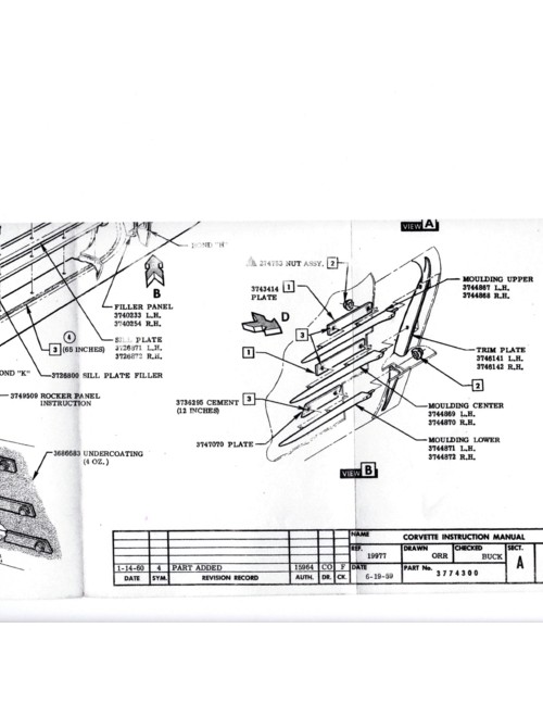
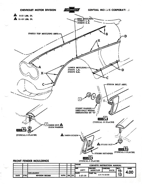
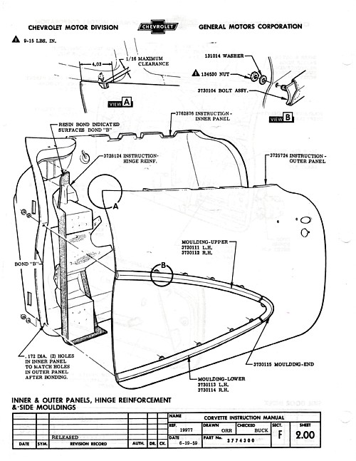
**********
07/10/2022
Hello!!
Just finished restoring a 1956 corvette with my husband and the help of a
few pros!! I am 5’4” tall and 125 pounds and can barely squeeze my legs
under the steering wheel. It’s so hard to work the gas and brake without
bending my leg sideways.
To make matters worse, the gas pedal is soooo hard to press down. It is a
265 dual carb.
Jim K. in PA helped restore it with my husband. We are heading to
Carlisle in August for its debut from driving it is going to be so hard for
me!!
Help!
Thank you!
Liz
From:
John Spencer, Red River Chapter President: Liz - Early
C1s are tight. I am 5'6" & I have a 54 that has a 4-speed. I had to pull down
the seat springs to give me enough room to move my legs to operate the clutch
and brake. Even with the shortened seat cushion I have to operate bow legged.
Some people choose to substitute the standard (17.2 in dia.) steering wheel for
an aftermarket one that is only 15 in. dia. I have attached the cockpit specs
for a 56-57 for you to review - make sure you have all the room GM intended.
PS: beautiful car.
Here are the specs:
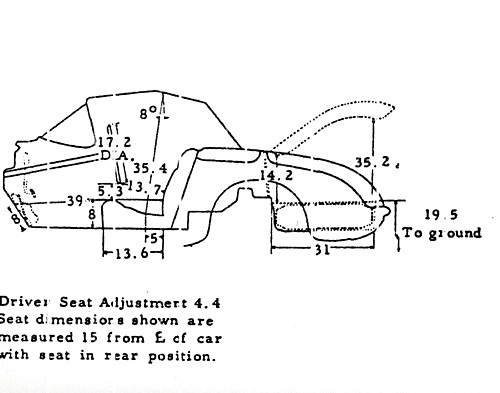
Liz - Also...; regarding the gas pedal - check the linkage position and
springs on the carbs. Are they set up for progressive throttle ??
**********
07/01/2022
I would like to do engine upgrade on 61 Corvette 245HP w/ Dual quads. Would like
to install
Duntov 097 cam, but I don’t want to remove the heads. Please advise
Thanks,
Glenn
From:
John Spencer, Red River Chapter Advisor: You don't have to remove the
heads to stab a new cam. You have to remove the valve covers - loosen the
rockers to remove the push rods - remove the intake to reveal the lifter galley
and pull the lifters. Be sure you keep the push rods and lifters in order to
replace them in the same locations they came from. Check your lifters for wear
before you re-use them on a new cam. Use STP or a good engine rebuild lube when
putting everything back in place.
From:
Verle Randolph, Red River Chapter VP:
It is not necessary to remove the heads.
Remove grill, fan shroud, radiator.
Remove oil filter for ease of access to the pan bolts.
Remove pan, balancer, water pump, front cover, distributor, intake manifold,
valve covers from engine.
This gives you access to everything you need to swap cams.
Remove spark plugs so the crank shaft is easy to turn.
You will have to back off the rocker arms so you can remove push rods and
lifters. You don't need to remove rocker arms unless you are changing them.
Check condition of rocker arm pivot balls and socket in the rocker arms.
Check push rod ends for wear.
A friend with experience in working on small block engines will be welcome
help and two sets of hands make things go faster.
With all parts, gaskets, tools in hand can easily be done in a day. A half
day if things to well.
You will need a puller to get the balancer off the front of the crank.
Verle
**********
06/29/2022
Suggestions for Alignment setting?..
Thanks
Larry
From:
Larry Pearson, SoCal Chapter Advisor:
Larry: The front end alignment specifications for 1953-1962 Corvettes is
found on page 14-1 of the Corvette Servicing Guide, Chevrolet publication
ST-12. This is the only official Chevrolet service manual for the 1953-1962
Corvette, and it is a"must have" for all C1 Corvette owners. It is available
as a reprint from all the major Corvette parts suppliers.
The front end alignment specifications for 1953-62 Corvettes are:
Caster: 2 degrees, plus or minus 1/2 degree.
Camber: 1/2 degree, plus or minus 1/2 degree
Toe-In (per wheel): 1/16"-1/8"
Larry Pearson
From:
Bill Huffman, Michigan Chapter President: Larry,
The C-1 alignment
article was published by Vette Magazine in their
June
2002 edition. It was an article by Richard F Newton.
Michigan Chapter
has a copy on our website,
www.solidaxlecorvettemi.com.
You may have to get our webmaster's
permission on signing in, but that's easy.
The article is a pdf file.
https://www.solidaxlecorvettemi.com/_files/ugd/0f0903_dd0ca5b654ea420bbc1d5ff55766753c.pdf
Same alignment works for both bias-ply and radials, but radials give a more
stable ride.
I take a copy with me to the alignment shop so the tech will
know how.
Bill Huffman, Pres.
Michigan Chapter SACC
**********
06/19/2022
How to replace upper eye brow moldings on a 1959 Corvette,
Thank you.
Don
From:
Larry Pearson, SoCal Chapter Advisor:
Don: I am assuming that you are referring to the front left and right
upper outer grille moldings. These are chrome plated zinc metal die
castings. Corvette Central sells new replacement moldings. Each of the
four outer grille moldings have three 1/4-20 plated steel mounting studs
threaded into them. They attach to the fiberglass body from inside the
fender with 7/16 inch steel hex nuts which thread onto the studs. These
mounting nuts are easily accessible without removing the front wheels if
you turn the wheel in.
It is very possible that your hex nuts are rusted onto the mounting
studs, and trying to remove them will either break the mounting studs or
cause them to unthread from the moldings. If the studs break off close
to the castings, you will have to drill them out, a very difficult
procedure. New replacement studs can be made from 1/4-20 bolts of an
appropriate length by sawing the hex head off. New 1/4-20 nuts are
readily available from hardware stores. Use 1/4 inch flat and lock
washers under the mounting nuts. Apply grease on the end of the studs
before installing the nuts to prevent future rusting.
Larry Pearson
**********
06/14/2022
I purchased a restomod wonderbar radio for my 1959 corvette. I had a mobile
tech come out and install it. Warranty on installation is over. It worked fine
for awhile then just recently when I turn off the ignition to lock the radio
stays on. The radio company did three bench tests and found nothing wrong with
the radio. However, now it won’t turn off. I have to unplug it. Is it in the
ignition switch wiring?
-David
From:
John Spencer, Red River Chapter Advisor: Probably an ignition switch
problem. The radio itself don't know whether you have the car running or not.
As long as it has power (12V) it will stay on, unless turned off manually with
the Vol control knob. The circuit should be a 14Ga. pink wire off the ign sw -
to the fuse panel - 14 Ga Yellow, to the radio connector. The Gas and Temp
gauges are fed from the same Ign Sw terminal. Does the gas gauge drop to 0 when
you turn off the ignition? If so the radio is wired to an incorrect source
(12V). If NOT the ignition switch is faulty.
From:
Larry Pearson, SoCal Chapter Advisor:
David: locojohns (John Spencer) did an excellent job with his answer.
Additionally, turning the radio Volume control fully counterclockwise until
it clicks must turn the radio off, even if the ignition switch won't, and
you are saying it doesn't. If that is the case, the radio on/off switch is
defective and needs to be repaired, in addition to the problem with the
radio not turning off with the ignition switch, which it should. You say
that the radio worked fine until recently. It is hard to believe that two
separate things went bad at the same time.
Larry Pearson
**********
06/10/2022
Hi:
Anyone the San Fernando Valley, or L.A do fabulous minor body work
and painting?
Joe
Also, my Electronic Power Assist Steering
system has aggravated the cars tendency to wander and reduced its ability to
re-center from turns. I’m told this might be remedied by adding caster to the
upper A-arm pivot and installing a second shim. Can you tell me if adding shims
is a time consuming job or a simple one please?
From:
Bill Huffman, Michigan Chapter Advisor: Joe,
The Corvette Servicing
Guide ST-12 shows a clear picture of the 3733477 shims, which are the tapered
aluminum spacer that sets caster on C-1's.
They are located between the front
frame rail and the front suspension crossmember. After 60 years both shims could
be deteriorated due to galvanic action if you live near the ocean.
To
replace them, the front crossmember assembly must be unbolted from the frame (8
bolts on each rail) and dropped down far enough to clean & paint the affected
areas and reassemble with new shims & fasteners. Be careful of the gas & brake
lines if you do this.
However, I suspect that the accumulated
backlash/looseness in the steering system may be your biggest issue.
You
need to check for looseness in the steering gearbox, the two drag link bushings,
third arm bearing, tie-rod ends, kingpins & the wheel bearings all of which are
simpler fixes before you opt for the major surgery.
Good luck with your
project,
Bill Huffman, Pres.
Michigan Chapter SACC
**********
06/02/2022
I have 61 Corvette and all four hub caps keeps moving. It
will move enough that it would bend the valve stems. I rest all four hub caps
take the car out for a ride, come home and have to reset hub caps again..
I do have the correct rims for the car with four nubs on them. The wheel
cover only two delineated spaces on each hub cap. I was told I need four on each
hub cap. Please advise……Glenn
From:
Verle Randolph, Red River Chapter VP:
I have had the same problem with four nub wheels.
May need to bend the clips out a (very) little.
From:
Larry Pearson, SoCal Chapter Advisor:
Glenn: Starting in 1966, I have owned one 1960 and three 1962's and never
have experienced the problem that you are having. Except for some minor
appearance issues, the 1955-56 Chevy sedan rims are identical to the 1955-62
Corvette rims and, therefore, are not rare. I suspect that the wheel covers
that you are using might be reproductions, and that might be the cause of
your problem. Original wheel covers snap firmly into place and mount
tightly against the wheel rim. Grabbing the spinner, you cannot move them.
If yours are loose it might be possible to bend the areas where the wheel
nubs contact the lip on the wheel cover to make them mount tightly on the
rim. Original wheel covers are available, but will cost you at least $400
for a decent set. To stay with what you have, I suggest that you convert
your rubber valve stems to metal ones, which are readily available at tire
shops, and you will need a tire shop to install them.
Larry Pearson
**********
05/20/2022
The drivers side clamp that secures the top needs tightened. Would
appreciate your help on how to tighten it on my 62. Thank you.
From:
Larry Pearson, SoCal Chapter Advisor:
I assume that you are referring to the chrome plated clamp on the driver's
side that clamps the top front header to the windshield frame being loose.
The procedure to adjust this clamp is outlined in the official Chevrolet
Corvette shop manual, "Corvette servicing Guide", publication ST-12, on page
1-29, under the heading "PROBLEM B". If you don't have a copy of ST-12, it
is available as a reprint from all of the major Corvette parts suppliers,
and I highly recommend that you acquire a copy if you don't already have
one.
If you don't have a copy of ST-12, the adjustment procedure is a simple
one. Unlatch both right and left clamps and raise the top header off the
windshield frame with a piece of 3/4 " wood. If this is a hard top, you may
have to loosen the two front top hold down screws so as not to stress the
top assembly. Loosen the two large chrome plated Phillips head screws that
secure the clamp that needs adjusting to the top header, and you will find
that the clamp can be adjusted up and down to make it tighter or looser when
clamping the top header to the windshield frame. Adjust as necessary and
then tighten the screws. There should be an adequate adjustment range unless
the top header weatherstrip is damaged or missing.
Larry Pearson
**********
05/12/2022
New member here # 5130. 1960 model. I have two assembly manuals. Does
anybody or anywhere is there an explanation of the numbers and letters in these
books? My Mid America manual pg L71 has a 451247 screw. Is there footnotes for
these? Thanks, Jim
From:
Verle Randolph, Red River Chapter VP:
Jim,
I believe the numbers you refer to are GM part numbers. If someone has
an old parts book they may be able to look up the number and tell you
what the screw is.
Verle
From:
Larry Pearson, SoCal Chapter Advisor:
Jim: I am assuming that you are referring to the 1960 Corvette Assembly
Instruction Manual (AIM). The wonderful thing about the AIM's is that the
GM part number for every part, sealant, screw, washer and nut that was used
in the assembly of your 1960 Corvette is listed. However, except for
specialty hardware, none of the screws were listed for separate sale in the
parts book. Instead, the parts books state the size and length of the
hardware. For example, SCREW, (1/4-20 x 5/8"). I have a Corvette
parts book from 1972 and your 451247 screw is not listed in the part number
index. My AIM for 1960 does not have page numbers like L71, so I cannot
determine what particular screw you are talking about. Almost all hex head
bolts used in your car had a head stamping indicating the strength (grade
3,5,or 8) and the manufacturer's trade mark (A,E,U.TR, RBW, for example),
and the NCRS judging guides frequently specify these markings. Corvette
Central reproduces and sells some of the hardware specified in the NCRS
judging guides.
When I restored my 1962 Corvette in 1974, I cataloged every screw in the car
by the head stamping, the length, and the pitch of the thread. I then
cleaned them and had all of them re-cadmium plated and then I put them back
where they came from when I re-assembled the car. My 1962 Corvette has all
the original nuts and bolts, and they all look like new!
Larry Pearson
From:
John Spencer, Red River Chapter Advisor: I have an original Chevrolet
parts catalog for 1953 through 1973. I show no reference to any Chevrolet part
number 451247. If you can describe the application, I can probably identify the
screw if that's what you're looking for.
**********
05/07-2022
Hi - my 54 restoration is complete except for new convertible top. I
need a tan(beige) top. Is Al Knoch the only source, or are there other
suppliers
today?
Thanks,
Mike
From:
John Spencer, Red River Chapter Advisor: I put a canvas Al Koch top on my
54 in 2000. I’ve been very pleased with it.
From:
Larry Pearson, SoCal Chapter Advisor:
Mike: In my experience, go with Al Knoch. His products are considered to
be the best. The only problem I have had is with the length of his pads
that go under the top fabric and act to properly space the bows. Using his
pads on my 1960 and 62, they come pre-cut to length and were at least one
inch too short and I had to make compromises to make them work. This might
not be the case with the 53-55 pads. Local installer Jeff Reade has Al make
his pads longer, and they are referred to as the "Jeff Reade" pads. Call
Jeff at 310.570.5554 for more information.
One other problem is with the thickness of the top material that all
reproduction top makers are currently using. The original top fabric was
very thin and the top folded into the top compartment behind the seats with
no effort. The new material is very thick and stiff and it is very
difficult to get the top into the top compartment so the lid can close.
Again, this is for the 56-62 tops. I have no experience with the 53-55 top
material. Either way, there is nothing that you can do about it.
Larry Pearson
**********
05/04/2022
Hi... I'm trying to find where and which direction a distributor heat shield
goes on my car. As you well know, passenger side
bolted to exhaust manifold.
Any information you may lend will be greatly appreciated. 1959 2X4
Carbs.
Best,
Mike
From:
John Spencer, Red River Chapter Advisor: The driver side mounts just like
the passenger side - two tabs mounted to the inside bolts of the front and rear
exhaust manifold mounting bolts. See photos.
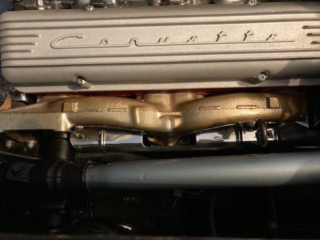 Driver's
shielding
Driver's
shielding
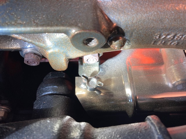 Front
side mount
Front
side mount
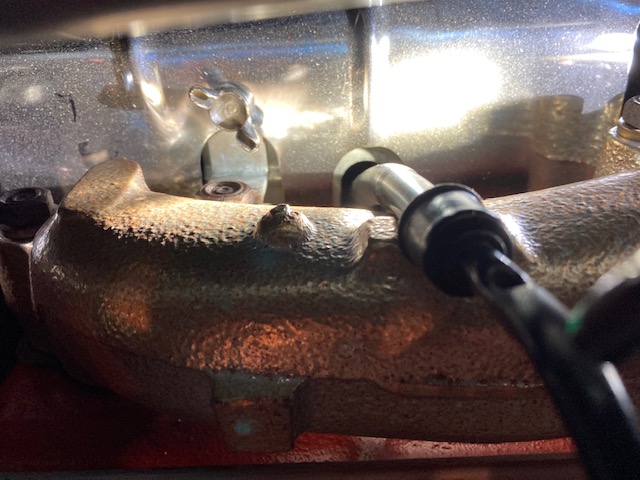 Rear
shielding
Rear
shielding
Corvette Central has a good illustration of the shielding and mounting
hardware. Pg95 - mounting brackets are identified as L-Brackets P/N 471125 (4
required)
Ffrom:
Larry Pearson, SoCal Chapter Advisor:
The chrome plated shields shown in the pictures are not all of the
shields.. They were installed on radio equipped Corvettes to shield the AM
radio from spark plug radio interference. The complete radio shielding on
your 1959 Corvette consists of five pieces: one on each side of the engine
as shown in the photos; two vertical pieces at the rear of the engine going
up to the distributor; and a large polished stainless steel cover over the
distributor and the ignition coil. Radio delete Corvettes got none of
this. This shielding was necessary because the Corvette fiberglass body
offered no shielding to the radio from the engine ignition radio noise.
This shielding was not needed with the metal cars and trucks, where the
steel body shields the radio.
There were, however, four separate spark plug wire heat shields installed on
all 1958-62 engines. They protect the spark plug wire boots from exhaust
manifold radiant heat that would damage them. They each attach to the
engine block on each side using a short 1/4 inch thread 7/16 hex head bolt
with captured external star lock washer, These heat shields were present on
all Corvettes. If you are using silicone rubber spark plug wires and boots,
these heat shields are probably not necessary.
Refer to Corvette Central's catalog under "Ignition Shielding" to see all
the parts and hardware needed for a complete radio shielding setup,
including the four spark plug wire heat shields, which can be purchased
separately.
Larry Pearson
**********
04/08/2022
I am trying to find the location for the stamped numbers on
the frames of my 1954 and 1962 Corvettes could you please help!
Chuck
From: Bruce Fuhrman, past Secretary of SACC:
I had a 1954 (but not a 1962). I had experience in CA in finding the S/N. The
S/N is stamped on the frame below the drivers lift cheek (on the bodily rear
end). It can not be visable, there is only less than in inch clearance from the
body! You can rub the sandpaper on the spot, and put chalk dust and an mirror to
observe it.
Good Luck!
Bruce Fuhrman
**********
03/23/2022
I am working a 59 frame off and am getting bac to body reassembly. Looking
over the grill and eyebrow surrounds and the studs used to affix them to the
body. Keen, corvette central and zip along with my original have various sizes
of studs. The grill surround appears to use 2 inch long studs on the outer most
“circumference” but when installed over 1” of stud is exposed. Is this correct?
From:
Bill Huffman, Michigan Chapter President:
Ron,
Those
vendors you mentioned, and most others supply diecast surrounds & eyebrows
from Trim Parts that were cast in GM's original tooling.
The studs
are shorter on the ends of the surround.
You have
most likely been to car shows and seen C-1s with 1 or more dimples in the
upper surround. Beware overtightening the washers & nuts on the
studs when you install them. The dimples are re-assembly damage.
Good luck
with your project,
Bill
Huffman, Pres
Michigan
Chapter SACC
(Discussion continued)
Thank you Jack, I just joined SACC this afternoon. What im trying to verify
is are the studs , 2 inch long correct. When installed and hardware on they
protrude about 1 inch and appear too long. The Assembly manual shows same part
number for all studs. But I have 3 lengths. Here is a picture of the upper grill
surround for my 59 with the studs installed.
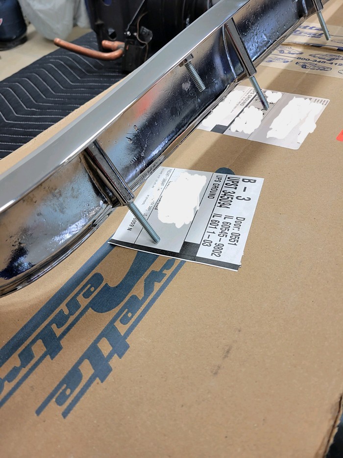
From:
John Spencer, Red River Chapter Advisor: Ronald - I have a 58 whose grill
surround is original, and the mounting studs are long like those shown in your
photo (approx. 2").
**********
03/08/2022
Hi, I Joined the SACC earlier this year #5112 and I’m looking forward to
the club activities. I just purchased a 1957 270 HP corvette this year. The
car was restored over a period of years finishing in about 2011. After going
through the NCRS judging process that concluded in 2013 the car was mostly
stored in a climate controlled room and obtained about 130 miles since the
restoration. The car was started on a regular basis during storage.
I am
now experiencing a starter issue. When trying to start the engine i will get a
whining noise from the starter. The starter is not engaging the flywheel just
spinning. This may happen two, three times in a row and then it does engage and
the engine will start.
Does this sound like a solenoid problem or could
it be the starter drive that is attached to the solenoid. My thought is since
this starter was rebuilt perhaps 12 to 15 years ago and only 130 miles on it
perhaps it is dirty or needs lubrication? Or is it a typical solenoid fault?
Thanks
Eugene
From:
Verle Randolph, Red River Chapter VP:
I would first check to make sure the starter bolts are tight.
When you turn the key to start position you should hear a metallic
click. That would be the starter gear engaging the flywheel.
Since the starter is just spinning the starter is not engaging the
flywheel but the solenoid is working enough to provide power to the
starter motor.
Get someone to help you turn the engine a little ways. Put the car in
high gear and push/bump forward or back a little just to turn the
flywheel some. Then, try the starter again. This is a check to see if
some ring gear teeth may be missing.
If the starter just spins after that I would remove the starter and
investigate the solenoid and the starter gear.
You can bench test the solenoid with a battery and jumper cables.
Positive battery to the large top post on the solenoid. Touch the
negative to the starter case. The starter must be securely attached to
the bench. When you touch the negative cable to the battery it will
torque over violently if not fastened down.
If the starter gear does not extend to engagement position remove the
solenoid and check the linkage.
Verle
From:
John Spencer, Red River Chapter Advisor: I agree with Verle, however, to
get the solenoid to kick in you have to apply 12V to the solenoid terminal
marked "S". This terminal is connected to your ignition switch. The battery
cable attached to the large terminal is always hot. When the solenoid is
energized it connects the Battery cable to the starter and pushes the starter
gear (bendix) into the flywheel. If the starter is spinning then the solenoid
is operating. BUT the solenoid also pushes the bendix gear into the flywheel to
roll the engine. The Bendix gear is a spring loaded and threaded assembly.
Normally the starter gear is on the end of the Bendix assembly (held there by a
spring). When the solenoid is activated the Bendix assembly is pushed into the
flywheel, with the gear at it's end, it engages the flywheel. When the engine
starts, the speed of the flywheel is greater than the rotational speed of the
starter and the gear is extracted because it is on a threaded shaft that
basically unscrews it from the forward position (disengages the flywheel). Once
the starter is rested - a spring pushes the starter gear to the START position
(end of the shaft), ready for the next time you need to start the engine. If the
spring that normally returns the starter gear is weak or broken the gear does
not return to the START position, thus when you engage the starter the gear does
not engage the flywheel. The whole Bendix assembly or the spring itself can be
replaced. I hope this helps - this is not a complicated repair. Getting the
starter off is probably the hardest part of the process.
PS: You can engage the solenoid without suffering the violent torque of the
starter by simply applying 12V to the starter terminal (marked "S") without
applying 12V to the battery terminal.
Follow-up:
This is a follow up question regarding the starter not engaging the flywheel
and just whining. I pulled the starter and i have it strapped to my bench.
When I put 12 volts to the large top post and ground the starter then put 12
volts to the s terminal the starter gear works fine. The solenoid shoots out
the gear and spins every single time. It is not
acting like it did when the
starter was bolted to the engine. I looked at the flywheel and all of the ring
gears look good. Could this be due to no load on the starter and not a very
robust bench test? I would hate to crawl back under and install back on the
engine and find out it still needs to be rebuilt.
From:
John Spencer, Red River Chapter Advisor: Eugene - does the drive gear spin
freely in one direction and lock up in the other ? The drive gear is suppose to
spin freely in one direction only. The large hub just behind the gear is a
ratchet. A Bendix assembly (or starter drive assembly) is only about $50 - I
might replace it just to see what happens. Good Luck - John
From:
Larry Pearson, SoCal Chapter Advisor:
The problem you are having is most likely caused by a worn out Overrunning
Clutch assembly. The pinion gear is attached to a cylinder that contains
what is known as a sprag. This is a one-directional clutch device. When
the starter is spinning the pinion gear against the flywheel teeth it fully
engages the starter motor shaft to the pinion gear and cranks the engine
over. When the engine starts, the internal sprag device disengages the
pinion from the starter shaft to protect the starter armature from being
over speeded and destroyed. The pinion gear then freely spins on the
armature shaft until the driver disengages the starter. When the sprag
wears out, it does not reliably connect the pinion gear to the starter
output shaft in the cranking direction.
To test the overrunning clutch action the pinion should turn freely in the
overrunning direction and must not slip in the cranking direction. You can
check this out with your fingers. Even if the clutch seems to be working
properly, I recommend replacing it if is old and the pinion gear teeth
appear to be worn. Also, check that the spring immediately behind the
clutch assembly is in good condition. If this spring is weak or broken, the
pinion gear will not be pushed far enough to engage it with the flywheel
teeth.
The Overrunning Clutch assembly is retained on the armature shaft with a
snap ring sandwiched between a thrust collar (in front) and a retainer ring
on the back side. Refer to a Chevrolet sedan shop manual to instruct you on
how to remove and reinstall the snap ring so that a new Overrunning Clutch
can be installed.
Larry Pearson
From:
John Spencer, Red River Chapter Advisor: Loose Starter
bolts - the bolts would have to be VERY loose to cause the starter to not
even try to mesh with the flywheel
Bad Bendix linkage - Possibly. This, however, is a very simple linkage
- i've never seen it fail. If so check the pivot pin. if it's missing
or not.
Bad Bendix Gear - Probably. Its a common problem - for the Bendix (not
the solenoid) spring to fail. This will cause the starter gear to "not
return" to the start position, thus not engage the flywheel when the
starter kicks.
If this is the problem - repeated
attempts to start the engine will eventually engage the flywheel because
the starter/Bendix shaft is threaded such that a sudden spin of the
starter will thrust the gear into the flywheel
Bad flywheel ring gear - Again possibly but not probably. If the ring
gear is bad - repeated attempts will not cause the starter to engage.
You have to bump the engine to a different flywheel position like you
describe.
I have attached a photo exposing the Bendix assembly. Note the spring
between the solenoid wishbone yoke and the starter gear. This is the
spring that fails and causes the starter gear to fail to engage the
flywheel, You can also see the thread on the starter drive shaft that
causes the gear to retract when spun by the flywheel when the engine
starts.
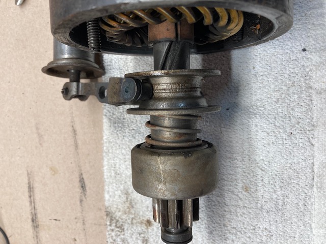
**********
02/24/2022
Is there a site where I can find some back issues
of the club magazine? I used to find some on EBAY, now I can’t find
any. Thanks Steve
From:
Bill Huffman, Michigan Chapter President:
This should be easy. Join SACC, then order all back issues available
from our new National Editor Alan Blay.
Bill Huffman
*Joining is easy! On our website simply click on "Online New Member
Application".
**********
02/08/2022
Looking for a qualified mechanic to service my 54 Corvette.

I live in downtown Dallas. The car will need to be trailered.

Contact information.

Anthony
From:
John Spencer, Red River Chapter Advisor: (*Note: Please be aware of the
disclaimer above). DMS Corvette Shop in Garland. 972-494-6900. I own a
54 and he's the only mechanic I'll allow near it except myself.
PS:
highly recommend association with the local chapter of the solid axle club.
Wealth of knowledge and support.
**********
From:
Bruce Fuhrman, Past Club Secretary:
Hi Anthony, (I assume you have a stove-bolt 6)
I do not have a recommend in downtown Dallas, but I do have
a recommends on oil!
Use a 30W conventional oil, not 10/30W oil. Add "ZINC" to the oil,
(ZDDP available in auto stores). The reason is; In the late 90's they
reduced zinc out of the oil (because every car had roller cams) and tappets
were obsolete.
Enjoy your "6",
Bruce Fuhrman
01/20/2022
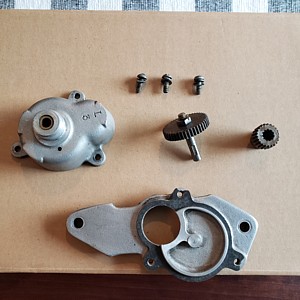 Hello,
I am trying to figure out if this tach drive unit is a gm part or a repro? If it
is a real gm part can you give me an idea of it'svalue? It cam as extra parts
with a 1958 that I bought in 1992. Mike
Hello,
I am trying to figure out if this tach drive unit is a gm part or a repro? If it
is a real gm part can you give me an idea of it'svalue? It cam as extra parts
with a 1958 that I bought in 1992. Mike
From:
John Spencer, Red River Chapter Advisor: This appears to be a GM unit.
The markings are different than the unit on my 58 but I don't think that is
significant. You can purchase new drive units for approximately $110.00
**********
12/24/2021
Hello,
Is there an easy way to remove each of the cables from the
rear of the dash cluster (to twist off the knurled nuts)?
The way I've tried it get at them is to reach over the steering
shaft, but I need baby hands and fingers to grasp the nuts
Is there a better and easier way to reach them without dropping
the steering shaft?
Thank you
58 Newbee
From:
Larry Pearson, SoCal Chapter Advisor:
Rex. I own a 1960 and two 1962's, and I have been under there lots of
times, although it is harder now that I am 80. Lie on the floor on your
back with a light and reach up with your right hand and loosen the nuts with
your thumb and fore finger. I do this when I need to lubricate the cables.
If this doesn't work for you, then you will have to remove the instrument
housing, which is lots of trouble. To do this refer to page 1-6 in the
Corvette Servicing Guide, Chevrolet publication ST-12. This is the official
Chevrolet shop manual for C-1 Corvettes and is available as a reprint from
all of the major Corvette parts suppliers. This is a "must have" for C-1
Corvette owners who work on their own cars. You can't drop the steering
column enough to do much good.
Larry Pearson
**********
12/04/2021
Subject: 1958 corvette stock 283 cu in, 290 hp
Hi all, I’m looking for a approx. 600cfm carb to install on my stock
manifold. Is there a good carb out there that won’t need an adapter plate
for this application? Cannot seem to find a good rebuilt/rebuildable stock
carb. I’m concerned about height/clearance with hood. I had a 600 Holley
with adapter and had hood clearance issues when airfilter was installed.....
Jack
From:
Larry Pearson, SoCal Chapter Advisor:
Jack: You say that you have a stock 283, 290 hp engine in your 1958, and
you are looking for a 600 cfm carburetor to go on this engine. This engine
came with fuel injection, not a 600 cfm carburetor, The only engine in 1958
with a single four barrel was the 230 hp engine with a cast iron intake
manifold. The 245 hp and 270 hp engines had dual Carter carburetors. This
arrangement was continued through 1961, and became 250 hp in 1962. All
these single four barrel engines came with a Carter model WCFB carburetor.
Do you have the 230 hp intake manifold that will fit a WCFB Carburetor on
your engine? The Carter WCFB carburetors once were very plentiful, but now
can cost over $900 rebuilt to NCRS judging standards, which you don't need.
You should be able to find a WCFB carburetor online. Corvette Central
offers a rebuilding service.
Larry Pearson
**********
12/1/2021
I
have a question about 57 Corvette cross member bolts and some others on the car.
The Frame was painted separate from the cross member, as I understand it, and
thus some of the cross members were painted a more shiny color than the frame
and was assembled to the frame as it went along. With that being said how
would the bolts have been painted that hold it on to the frame? Second
there are several parts that were assembled to the frame after it was painted
like the axle bumpers rear springs just to mention a few. So were all
these bolts painted or not or just some of them and where would I person find a
list of what was and wasn’t painted.
Thanks a lot for your help.
Kermit
From:
Verle Randolph, Red River Chapter VP:
I assume this question is raised in anticipation of NCRS judging.
NCRS flight judging does not judge those parts. They do not raise the car
and it is too low for most people to get under to see the parts.
I painted my bolts black to go with the cross member and for protection.
If it is related to Bow Tie judging, those cars are placed on a lift so the
complete underside of the car can be inspected for originality. As part of
that process judges compare patina of various parts and something that has
been restored/painted will stand out.
If the car is that original/unmolested I would leave it alone.
Verle
**********
11/26/2021
I am a UK member looking for a
wiper motor cable complete with ratio box , my old cable is approximately
32.5 inches in length, please could you tell me if this item is available
and a part number if possible and contact details where I may be able to
source this part.
From:
Larry Pearson, SoCal Chapter Advisor:
Malcolm: Corvette Central sells rebuilt left and right hand windshield
wiper transmissions, complete with cables. The cost is $109 each side plus
a $100 core charge and shipping. They also used to provide a rebuilding
service. Their catalog numbers are 651080L and R. They also offer a
complete wiper upgrade kit that includes everything needed including the
motor. The car may have to be modified to install it.
Larry Pearson
**********
11/23/2021
I have a 57 I am doing. Are the bolts that hold the
Front Cross Member and several other parts like the motor mounts painted.
I have never seen a none restored car and know that some of the cross members
were painted gloss and some weren’t so they were installed after the frame was
painted thus my question about the bolts. Also stuff like the rear spring
mounts to the fame and shackle bolts and nuts just things like that because they
were installed after the frame was painted I think or were they? You know
upper/lower A arm bushings and things of that nature that was put on after the
frame paint. I am pretty sure the grease zerks were not painted because I
am old enough to remember that as I worked in a gas station and greased them.
Got any ideas?
Thanks,
Kermit
From:
Larry Pearson, SoCal Chapter Advisor:
Kermit: If you are restoring your car for NCRS Judging, obtain a copy of
the NCRS Judging Guidelines for your year car and follow what they say. If
not, I have made a study of the chassis painting over the years, but not as
early as 1957. I have a collection of photos taken by Motor Trend when they
road tested a new fuel injected 1961 Corvette. They put it on a grease rack
and completely photographed the chassis front to back. Also, there is a
book "Birthplace of Legends" that has assembly line photos taken over the
years at the St. Louis assembly plant. Here is what I have come to believe.
The frames were manufactured for Chevrolet by an outside supplier (I forgot
the name) and were dip painted with gloss chassis black paint before
shipment to the St. Louis assembly plant. There is a red stencil, upside
down, on the frame just under the driver's seat that gives a part number
with a manufacturing batch number after it and a manufacturing date below
it. Chassis black paint is identical to radiator paint, and is an
inexpensive black tar like coating that is solvent based. It dries but does
not cure like enamels, and is easily removed with any petroleum based
solvent like mineral spirits and lacquer thinner. Next the front and rear
suspensions were installed, the exhaust system, the brake system including
the master cylinder (sticking up in the air by the vertical brake line), the
fuel lines, and then, finally the engine/transmission and drive shaft. Just
before the body installation, everything got spray painted with chassis
black paint (except the engine): The front and rear suspensions (including
zerk fittings), the brake drums and backing plates and rubber brake hoses,
the exhaust system including the mufflers, the left side of the master
cylinder and its brake line, the drive shaft, the cast iron transmissions (3
and 4, speed and PG) with black overspray on the bell housing and bottom
clutch cover. The frame was not purposely re-painted, but parts of it
obviously did. The result wasn't pretty, and it wasn't meant to be. They
wanted to rust proof the entire chassis before the body got installed. I
have pictures to prove all of this.
As far as the front engine mounting to the frame goes, in the beginning it
was done as shown in the factory Assembly Instruction Manual (AIM). The
verticals were bolted to the frame and when the engine was installed, the
rubber engine mounts were set in place with the steel tube and the engine
assembly with the gloss orange painted cross member was set on the rubber
mounts and bolted with the lock nut thick flat washer, and radio ground
strap on top. The lock nut, the flat washer and the ground strap have no
orange paint on them. This is how your 1957 was done.
Sometime after 1957, this all changed. The AIM never got updated to show
this. My un-restored 1960 was done as described here. The verticals, the
rubber engine mounts radio ground strap and the cross member got assembled
in some sort of fixture. This was probably done at the St Louis plant, but
could have been done at Flint Engine. This entire assembly got installed
on the engine. Just before the engine got painted, they masked off the
verticals and the rubber engine mounts. Then everything else got painted
orange, including the lock nut, the large flat washer and the end of the
radio ground strap.
This gives you something to think about . Again, if NCRS is going to judge
your car, restore it like they say. In my experience, NCRS and I do not
agree on a lot of things. The judging people at NCRS are very stubborn and
will not correct their publications when proven wrong. But I can prove what
I believe. They can't.
Larry Pearson
**********
10/30/2021
Hello,
>
>
> I have a 62 corvette, 300 hp with a t-10 4 speed
trans. Recently, it started to grind slightly when I shift from 1st to 2nd.
After the car warms up it doesn’t do it. What do you suggest? I’m thinking to
change the oil to see if that will fix it. What transmission oil do you
recommend?
>
> Thanks,
> Chuck
From:
Larry Pearson, SoCal Chapter Advisor:
Chuck: The proper lubricant for your transmission is 90 weight gear oil.
This is available in quart bottles at all auto parts stores. But I don't
think that the gear oil is the cause of your transmission grinding.
Check your clutch linkage adjustment. There should be about one inch free
pedal in your clutch pedal before the clutch linkage starts to engage the
clutch throughout bearing. If this free travel is much in excess of one
inch, depressing the clutch pedal all the way to the floor may not cause the
clutch disc to fully disengage from the flywheel and this may cause a
grinding sound when attempting to shift into gear. But if this were the
case, there would be grinding when shifting to all of the gears. Clutch
free travel adjustment instructions are found on page 6R-3 in GM's shop
manual for all C-1's, Corvette Servicing Guide, publication ST-12.
Reprints of this manual are available from all the major Corvette parts
suppliers.
Your transmission gearshift linkage may need adjustment for second gear
engagement. The adjustment procedure is, unfortunately, not found in the
ST-12 shop manual. It is found in the 1961 Chevrolet Passenger Car Shop
Manual on page 12-29. The 1-2 shift rod is the long one going to the front
shift lever on the outside of the T-10 transmission. With the shifter in
the second gear position, make sure that the the transmission lever for 1-2
is all the way forward.
If none of this solves your problem, your transmission may need servicing.
Second gear is a particular problem with the T-10 transmission. With heavy
use, the second gear synchronizers fail to keep second gear engaged, and it
will come out of gear, particularily when lifting off the gas pedal. I
seldom use second gear in my three C-1's. If you look at the gear ratios,
the third gear ratio is close to second gear ratio in the 3-speed
transmission. So why bother using second gear? I shift directly from first
to third. I only use second when stuck in traffic.
Larry Pearson
**********
10/25/2021
Attached is a photo of the hubcaps that were on the '54
Corvette that I recently purchased and I know they are not Corvette hubcaps but
wondered if anyone can identify the year, make and model that these were
originally used on? I am guessing a 50's vintage Chevrolet? Thanks for your
help, John
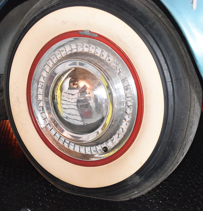
From:
John Spencer, Red River Chapter Advisor: Photos of the first Corvettes off
the production line in 53 exhibit a hubcap very close to that in your photo.
They are believed to be that of a 53 Bel Air. Investigate passenger car (Bel
Air) caps around your year. I have attached an article from "The Real Corvette
(pg29)" FYI.
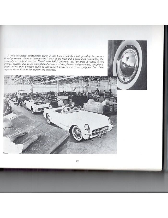
**********
I’m in the process of restoring my 1961 Corvette as original as possible. I
have a restored set of original Seatbelt Hambones which are silver cadmium
coated. The vehicle is black with silver coves and I was wondering if you
know what color and finish the Hambones should be. I know they do get some
over spray on them when painting the body.
Can you please help me out?
Regards
Dave
From:
Larry Pearson, SoCal Chapter Advisor:
Dave: I assume that you are referring to the two outboard seat belt support
assemblies that attach with four bolts to a reinforcement riveted to the
floor pan under the car. They were in place when the exterior was painted,
and you can expect at least some exterior overspray to be on them. They
could actually be completely painted black, but this was not deliberately
done, because these supports were not visible with the seats in place. If
you are having your car judged by NCRS, don't worry about the appearance
because the judges can't see them.
Larry Pearson
**********
Members,
Does anyone know where I can buy touchup paint for my 1958 sonwcrest
white Corvette?
Thanks.
Ed
From:
John Spencer, Red River Chapter Advisor: Where are you located? I
recently purchased 58 Charcoal acrylic lacquer from English Color in Plano,
Texas. They had to import it from their shop in Houston - but they still
supplied it.
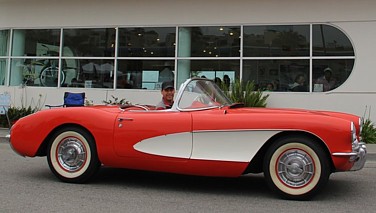 From:
Joe LeMay, SoCal Chapter Advisor:
From:
Joe LeMay, SoCal Chapter Advisor:
I buy from Paintscratch.com
I use Venetian Red in 1 oz and spray cans.
Joe
**********
09/21/2
I ordered a convertible top
front right latch (for my ’61) in July and was told in August that it
was backordered, and last week I was told the order was cancelled as
they could not get the part from the manufacturer. Every place I look it
seems that they are now out of stock even though they are still
advertised in most catalogues. Any suggestions on where to go to
get one?
Chris
From:
Larry Pearson, SoCal Chapter Advisor:
Chris: Try Sully's Tops, in Fresno California. They reproduce the entire
top frame and sell individual parts. Call 559.291.8677, 800.451.8680,
http://www.sullystops.com.
Paragon sells used parts.
Larry Pearson
**********
09/14/2021
Greetings!
I have a 54 Corvette restomod that I have owned for about 15 years. I have
a 350 sbc in it, although from most perspectives it looks original until
the hood is opened. The original sway bar is notched, which prevents me
from installing a larger and much-needed radiator fan. Can you offer me a
resource to find a sway bar (perhaps straight or notched in the other
direction)/that will fulfill my need? I’ll be most grateful.
I didn’t know this club existed (silly me,). I just joined.
Thanks much!
Richard
From:
Larry Pearson, SoCal Chapter Advisor:
Richard: You don't say what type of radiator fan you are using. If
you are using a water pump mounted fan, the notched (forward) sway bar
should not be a problem. It would offer more fan clearance than a
straight sway bar would. But if you are using an electric fan mounted
on the radiator, then the forward notch would be a problem. The forward
notched sway bar was necessary due to the considerable length of the six
cylinder engine. When the small block V-8 was introduced, the sway bars
were made straight, because this engine is much shorter than the six.
It is interesting to note that the better heat rejection of the V-8 (due
to the much shorter path from the exhaust valve to the exhaust port with
the new V-8 cylinder head design, resulting in less exhaust heat being
transferred to the coolant) allowed Chevrolet to use a smaller radiator
for the V-8 in sedans. The V-8 also weighed less then the six, and cost
less to manufacture. In 1955, I am told that it cost Chevrolet about
$65 to manufacture a 265 V-8 engine, exclusive of overhead costs. They
should have charged less for the V-8 than the six, but they didn't,
In answer to your question, any 1956-62 sway bar is straight. They
should be easy to acquire.
Larry Pearson
**********
Hi, I have a 61 Corvette 283 Engine w/ DUAL
Quads 245 HP. What type of gas should I use in this engine.
I have been running a premium fuel w/ Lucas Octane Booster.
Can I switch to 87 Octane and run Octane Booster ?
Or is there anything better that you can recommend.
Thanks,
Glenn
From:
Bill Huffman, Michigan Chapter President:
Glenn,
I'm going
to assume you mean you are using unleaded Premium 93 Octane 10% ethanol
gasoline with octane booster in your car.
Around
home, I use 100% recreational 90 octane unleaded gasoline in my 1960 230HP
283 that has with same compression ratio as yours and it runs fine.
Your
car's components were not designed to deal with the corrosive effects of
ethanol long term.
On long
trips like the recent convention trip, I had to use the Premium 93 gas and
filled up on the good stuff when we got home.
However,
if if your engine has not had hardened valve seats installed in the stock
heads, you probably need to add lead substitute as well.
Bill
Huffman, Pres.
Michigan
Chapter SACC
From:
Larry Pearson, SoCal Chapter Advisor:
Glenn: I own a 1960 Corvette with the base 230 hp engine, and it is
completely original and has never been rebuilt. This is the exact same
engine as the 245 hp engine, except that it has a single 4 barrel
carburetor. Both engines have a 10.5 compression ratio. I live in
California, which has the worst gasoline in the country. Premium is 91
octane and $5.00+ per gallon. My 60 runs just fine with the 91 octane
gasoline and no octane booster. Occasionally I add a lead substitute to
protect the valve seats, but I don't think that this is necessary for
the low performance engines.
If your engine is original or has been rebuilt to original specs and is
properly timed, you should have no problem using 91 or better octane
pump gasoline. If it pings when driven hard, retard the timing. I have
a 62 with 11.25 compression and have had no luck with octane boosters.
I have found that 1/2 quart of lead additive per 10 gallons of premium
boosts the 91 octane to an acceptable level for this engine. Lead
additive is available on the internet.
Larry Pearson
From:
Joe LeMay, SoCal Chapter Advisor: You did not say whether your motor
runs in a manner that it needs octane booster. That is important to the
question. The stock configuration was 9.5 compression with flat top
pistons. The combustion chambers were small on the stock heads and 0.016"
head gaskets were used. Do you know whether the configuration is stock or
was the motor rebuilt with 0.030 or thicker composite head gaskets?
If you are getting pinging during acceleration, have you backed off on
the timing?
We need more information and I am inclined to say your motor does not
need anything special in the fuel.
With ethanol additive gasoline, I would use 1/2 oz. of ATF per gallon of
gasoline.
**********
08/29/2021
I had a tail light pigtail short out and now I have no taillights. Any quick
suggestions to look for?
From:
John Spencer, Red River Chapter Advisor: Probably a fused wire. Start at
the light switch and work your way back.
**********
08/21/2021
Tech Help,
September
2020 and April 2021 posts to your tech team and review of past posts were
a valuable source to remove and install the speedo and tach with newly greased
bearings on my 59.
Now I think the fuel pump failed.
Paragon no longer stocks the AC 4656 fuel pump as mentioned on this thread.
It seems it is no longer produced. Does anyone have a source that
still has one. I am leery about purchasing a reconditioned original on EBay.
Anyone have experience with rebuilding these pump?
Eric
From:
Larry Pearson, SoCal Chapter Advisor:
Eric: You say that you "think" that your fuel pump has failed. Did you
test it? Most vacuum gauges will test fuel pump pressure. Also, you can
disconnect the fuel line at the carburetor, hook a rubber hose to it and run
the hose to a can or large bottle, start the engine (pouring gas down the
carburetor if there is no gas in the carburetor) and see if the pump pumps
gas into the bottle. If it does, your pump is probably good.
Your carburetor either has a built in fuel filter or an external fuel
filter. Remove the external filter or the bronze internal filter element
and try to blow through it. If it is plugged up, that is the problem and
replace the element.
If you need to rebuild or replace your old pump, Corvette Central sells
rebuilt 4656 pumps or rebuild kits. The Chevrolet passenger car shop manual
for your year tells you exactly how to rebuild your pump from a rebuild
kit. If you decide to rebuild your old pump, do not attempt to
replace the rocker arm pivot shaft. The ends are staked to keep the shaft
in place, and it will be very difficult for you to properly stake the ends
of the replacement shaft. I have not encountered a shaft so worn that it
needs replacement.
Larry Pearson
From:
Joe LeMay, SoCal Chapter Advisor: Also, You can get the car to run for
long enough by pouring gas into the area where the metering rods are. Then
start the car and see if there is any flow from the disconnected fuel line.
**********
08/16/2021
In sorting out parts I need for the
restoration of a '54 I recently purchased (stored for over thirty years), I
have a seat frame and adjusting rails for the driver's seat but nothing but a
seat bottom and backrest for the passenger seat. Doesn't the passenger seat
require a similar frame? I was told the passenger seat was fixed (no adjusters)
how does it attach? Is the attached drawing for a '54 drivers seat?
Thanks, John
From:
John Spencer, Red River Chapter Advisor: The passenger seat on a 54 is not
mounted to a frame. The spring sets (bottom and back) mount directly to the
floor and bulkhead of the car itself. I don't know of anywhere the brackets
(more like clips) are shown. If you can't find any references to help you - I
can take a photo of mine and send it to you. Good luck - John
From:
Bruce Fuhrman, past club Secretary:
Your are right, the passenger seat is
not adjustable. You are missing the anchor plate (front/rear)
I suggest you make from steel? The bolts come from the underside.
Good luck,
Bruce Fuhrman
**********
07/23/2021
Rebuilding 62. All I currently have is a green and yellow
wire that was hooked to the old neutral safety switch. From
what I am reading, I should have two purple wires. I took
the tape off the wiring and see that the yellow wire
actually is one of the purple wires which leaves now with a
green and purple (yellow). I cannot find anything listing
on the wiring diagram for the NSS so am at a lost where or
how this is supposed to be connected except it looks like it
should go to something on.
From:
Larry Pearson, SoCal Chapter Advisor:
Deb: The 1962 Aluminum Powerglide transmission is option (RPO) 313. The
1962 Aluminum Powerglide is a completely new transmission that replaces the
cast iron Powerglide used in 1961 and earlier Corvettes. To find out how
the Neutral Safety Switch (NSS) mounts and how the wiring harness is routed,
you need to purchase a copy of the 1962 Corvette Assembly Instruction Manual
(AIM), which is available from all the major Corvette parts suppliers. The
RPO 313 section is seven pages long and shows all about the installation of
the NSS, but it does not explain or show how the NSS wiring harness connects
into the car wiring system. The purpose of the NSS is to prevent the
starter from activating unless the transmission is in Park. It somehow
connects in series with the purple wire in the car's wiring harness that
activates the starter solenoid. It appears in the passenger car shop manual
that there is some kind of adapter on the back of the starter solenoid that
the NSS wiring harness connects into. Contact Lectric Limited at
708.563.0400 to see if they can help you with the NSS wiring harness. They
reproduce all the wiring harnesses for your car.
Larry Pearson
**********
07/15/2021
I recently became a member and received my member number
today.
I have enjoyed reading the great advice in the technical help.
I tried a search to see if my question was already answered
previously to avoid asking the same question over again, but was
unable to find anything.
I am wondering if anyone has advice on installing the radio antenna
on a 1961.
A former owner replaced the original antenna with an antenna from
some other vehicle. I recently purchased a correct antenna and
reviewed the instructions in the 1961 service manual. Though it
seems straight forward, the part I am finding a bit tricky is making
sure that the bezel that sits on top of the fender is in the correct
position. When I tighten the cap, and check the antenna with a
level, it is not straight up and down. Perhaps it is not supposed
to be straight up and down. I do not know since the car did not
have the correct antenna before I changed it. Another concern is
that when I tighten the cap, I would think that it should contact
the bezel evenly all around, but in my case it makes full contact on
one side, but has a very, very small gap on the opposite side. I
have tried refitting it a number of times, but still come up with
the very small gap on one side. From a distance, it all looks
great, but if I could find out how to make it even better, I would
appreciate it.
Thank you for taking the time to consider my question.
Bruce
From:
Bill Huffman, Michigan Chapter President:
Bruce,
Welcome
to SACC!
If you
bought the whole antenna kit, there should have been a strap/clamp that
attaches the lower body of the antenna to the wheel well inside the trunk.
This
attachment determines the antenna angle coming out the top of the rear
fender. The chromed bezel just covers a big ugly rubber gasket sealing water
out of the trunk.
You, as a
guy who really cares, are putting far more thought into its alignment than
the assembly operator who originally installed it in 1961.
Relax and
enjoy your car because none of them were born perfect.
Bill
Huffman, Pres.
Michigan
Chapter SACC
From:
Larry Pearson, SoCal Chapter Advisor:
Bruce: You mention a 1961 service manual. I have never heard of such a
thing, except for the passenger cars. The Chevrolet Corvette Servicing
Guide, publication ST-12 is the only official shop manual that Chevrolet
produced for the C1 Corvettes, and it attempts to cover the entire
1953-1962 production run. It is a "must have" for all C1 Corvette
owners who work on their cars. If you don't have this manual, it is
available as a reprint from all Corvette parts suppliers. The radio
antenna installation is covered on page 13-4. Figure 3. Although this
figure is supposed to apply to all C1 Corvettes, it actually is
specifically for the 1961-62 Corvettes, which is exactly what you are
looking for.
You don't say where you got this "correct" antenna. What you have may
actually be for a 1956-60 Corvette, which installs through a rounded
fender top rather than the rather flat sloped fender top of the 1961-62
Corvettes. The 1956 through 1960 antenna assembly is slightly longer
than the 1961-61 because of the longer height in the trunk compartment,
but it might work in your 1961 trunk. Corvette Central sells the fender
top hardware if you have the earlier setup.
I assume that your car originally had a radio installed by the factory
and, therefore, that the hole in the fender top is in the correct
location so everything in the trunk properly lines up. All vertical
mast antennas need a ground plane to work properly. On metal car
bodies, the car body is the ground plane. On the Corvette, the frame is
used as the ground plane, and this connection is provided by a copper
strap that connects the antenna housing to a bolt accessed through an
access cover in the trunk that electrically connects to the frame, as
shown in Figure 3. Also the frame must be grounded to the engine block
with the two heavy copper ground straps that connect the frame to the
engine mounting bracket shown in Figure 6 on page 13-7. On Corvettes,
the engine block is the ground point for all electrical systems on the
car.
Larry Pearson
**********
07/06/2021
Good Afternoon :
I acquired a 1954 corvette 10 years ago. The vehicle did not have the
original engine or transmission.
After many years of searching. I found
an original 54 corvette engine and transmission. I had the engine and
transmission rebuilt.
The question that I am asking is the timing of the
engine. I have the beebee on the flyweight in line with the pointer.
The distributor rotor on number 1 cylinder on the cap. When I crank the
engine over and check the to see if the distributor rotor in on number 1
again it seems the it is off from the original setting.
Am I doing something wrong.?
Your help would be greatly appreciated
Thank you
Scott
From:
Bruce Fuhrman, Past Secretary: Hi Scott,
Is the engine running? If not,
there is something wrong. Be sure the compression is #1 and not exhaust.
Do this by taking the sparkplugs out and checking the compression in #1.
It may be the installed the distributor off by a gear?
If running- I had a '54 and it had the original engine &
transmission. During a transmission o'haul they could not locate the
proper flywheel (the teeth were worn out) by the starter, so they
reversed it! It worked out, BUT, I lost the timing mark! I
simply used a Dwell meter to set the points and drove the car till
there was no "ping" and used the Dwell meter again when replacing
the points. The proper dwell is 40.5-47.5 degrees, and the timing is
on the beebee.
Good luck,
Bruce Fuhrman
From:
John Spencer, Red River Chapter Advisor:
1- Rotate the engine until the timing pointer lines up with the BB or circle
on the
flywheel.
2- Adjust the points for proper dwell. Rotate the distributor until the
points are on a high point of the distributor cam. Adjust the points
for a 0.16 gap (establishes an approximate setting)
3- Connect a ohm meter between the points feed to the coil and ground
(disconnect from the coil). When the points are closed the ohm meter
should read 0 ohms. Rotate the distributor until the points just open
(ohm meter will jump to MAX ohms). Lock down the Distributor.
4-
Note where the distributor rotor is pointing - it should be pointing to
No.1 plug terminal.
5- If you need to adjust the dwell you will have to re-adjust the
timing.
Addendum to above answer.....
You are not looking for where the distributor rotor aligns with No.1 -
you are looking for where the points break associated with No.1
**********
06/26/2021
HELLO EVERYONE, I am
putting the finishing touches on my 1960 corvette and I realized I
did not know what the orientation of the door lock knobs should be.
I looked at a number of C1s on the internet but saw multiple
orientations. So, in the unlocked position where should the
lock “point”; to the right, down,??? Thank you for your time.
From:
Larry Pearson, SoCal Chapter Advisor:
Years ago, I had the good fortune to be able to purchase 8x10 glossy B&W
prints of photos that Petersen Publishing took of new Corvettes they did
road tests on for 1959, 1961 and 1962. Most of these were not used in the
magazine articles. They all show the position to be straight down. If you
are having NCRS judge your car, position them the way they tell you to in
their judging manual, or they will make deductions. NCRS is "always"
right. Years ago, I gave up trying to get them to fix their mistakes.
Larry Pearson
From:
Verle Randolph, Red River Chapter VP:
I tried my in several positions and picked the position that worked best for
me.
As Larry said, if you are having it judged, do it like their manual says.
Verle
**********
06/25/2021
Hello folks. My ’58 is a 245hp and T-10 4-speed setup.
Normally, shifting is smooth and secure. But, on very rare occasions the
shifter linkages somehow get locked up (happened at parking-type low speed,
probably going to reverse but really don’t remember). The immediate
correction is crawling under (not always easy) and jiggling linkages. I’ve
had this car 20 years; I think it happened twice, but the first time may
have been 60 years ago with my first ’58.
My question is – any clues as to what to look, for to avoid this
kind of lock-up? Thanks, Al
This photo was taken under car in 2019 when it had locked-up – hit or miss
with cam at arm’s length!
From:
Bill Huffman, Michigan Chapter President:
Al,
I assume
you have a stock '58 shifter with the spring as a detent to separate 1st &
reverse shift action. In all the efforts to steer/ shift/ brake and the 360
visuals related to having no RH rear view mirror, it gets pretty busy for us
in the drivers seat.
After 63
years, I'll bet that shifter spring isn't as rigorous in its lock-out
function as it used to be, allowing both 1st & reverse to try to engage at
the same time.
Hello
shifter lock-up.
Either
refurb or replace the spring, buy another '57-'58 stock shifter or you might
want to upgrade to the '59-'62 4 speed shifter w/ reverse lock-out handle.
It just
can't shift into reverse unless you actively want it to & pull the T-handle.
If you
have noticed linkage rattle, it might help to replace the bent cotter keys
with the correct GM G-clip.
Regards,
Bill
Huffman, Pres.
Michigan
Chapter SACC
From:
Verle Randolph, Red River Chapter VP:
I have experienced shifter lockup in the past. On mine the main problem was
it was worn out.
I rebuilt it with new bushings and shims to reduce/eliminate the slop in the
shift levers.
It may also be wear in the transmission side plate, detent spring, detent
balls, etc.
Last but not least, the shifter needs to be adjusted so the shift levers are
properly aligned. Misalignment can potentially cause the problem.
Many years ago I was with a friend in his 62 late one rainy night when the
shifter got locked up in one gear. We found a closed gas station with a pay
phone booth with light on. We jacked up the driver side of the car and I
slid under the car with water running on the pavement to pull the shift rod
to get it in neutral. While I was under the car a police car pulled up and
wanted to know what we were doing. After an explanation he asked a few more
questions and left, while giving us a suspicious look. My friend never did
adjust the shifter and had lock up problems more than once. I refused to get
under it after the first time.
Verle
**********
06/22/2021
I'm restoring my 60 vette. I noticed something very odd and no one has a
good answer. The bulk head between the trunk and the gas tank area is
missing . It was cut out very neatly. It appears it was once part of
the body. Why in the world would someone do that?? Any help will be
greatly appreciated. Thanks Bob
From:
Larry Pearson, SoCal Chapter Advisor:
Robert: I own a 1960 and two 62's, and the differences in the trunk storage
between the two models is very significant. The capacity of the 1960 and
earlier Corvettes trunks is quite small compared with the 61 and 62 models.
I suspect that a prior owner was looking for a way to get more trunk space
that was accessible from the trunk area and cut this panel out to easily
access the additional storage area that is there where the soft top goes.
Of course, if the car has a soft top, it must be in the up position to free
up the space. If your car has a hard top only, access to the soft top
storage area is not possible with the hard top in place. I have used the
soft top storage area for additional storage during long trips with my cars.
Larry Pearson
**********
06/18/2021
Does anyone make king pin
kit with needle bearing instead of bushing.
Also is a good thing to do ?
Also on differential fill plug leaks ? Install new plug with gasket, someone
total me to use copper gasket .
Please advise.
Regards,
Glenn
From:
Larry Pearson, SoCal Chapter Advisor:
Glenn: I finally got around to see if anyone manufacturers or sells a
needle bearing king pin kit, and found nothing. If it was available,
Corvette Central would have it, and they don't. The bushings will last
longer than you will, as long as you grease them. The factory recommends a
1000 mile interval for greasing all 22 grease fittings on your car's front
suspension. This is unreasonable, and I feel that you can safely go to a
2000 mile interval. Be sure to grease all four inner fittings on the upper
A-arms. They are hard to see and access, but if you ignore them, the
bushings will fail and are very difficult to replace.
The differential fill plug uses a leather gasket. If you replace it and it
still leaks, wrap the plug threads with Teflon tape and that should fix the
leak.
Larry Pearson
**********
06/17/2021
I am Chris and I have a ’61. Thank you Verle for your suggestion with my
tail light issue. Still working on it. My fuel gauge reads beyond full and
does not change. I heard from someone that it might mean the gauge is not
grounded. Any thoughts on how to check out my gauge? Second question, what
additive, if any, should I put in my tank when I fill up. I have put 93 octane
in it so far. It is the original 283 engine.
From:
Verle Randolph, Red River Chapter VP:
The fuel sending unit in the tank has a wire that should be attached to the
frame to ground it. Could be a problem on either end of the wire. Make sure
the frame connection is not rusted. Or, it could be a problem with the
sending unit its self.
The following was copied from another source and explains how to check the
fuel gauge.
"The
following information is reprinted with the permission of Mr. Fred Aldrich,
a.k.a. The
Chevelle Engineer.
Data presented are the same from his popular website with only minor changes
to spelling and overall format. Mr. Aldrich passed away in 2011 and
graciously allowed me to use some information from this website before his
passing.
1
) Locate
the fuel sender feed wire near the fuel tank. You're looking for a single
tan colored wire. With the tan wire disconnected at the fuel tank, the fuel
gauge should read past full with the ignition on. Wait a few moments as some
fuel gauges take a long time to respond. Touch the tan wire from the body to
any convenient ground and the gauge should read empty. If not, you have a
wiring problem or a bad gauge.
2) If the gauge responds correctly, the gauge
and wiring are OK. Next use a multi-meter to measure resistance to
ground of the sender wire connection on the top of the fuel sender
or the tan wire from the top of the fuel tank. Measurements should
track the fuel in tank.
Full - 84-88 ohms
Half - 40 ohms,
give or take
Empty - 0-2 ohms
If this doesn't check, then
sender or wiring on top of the tank is bad or the sender not
adequately grounded. Senders are typically grounded by a black wire
which is welded to the sender and attached to the body with a sheet
metal screw.
3) If the sender checks OK but
gauge and wiring don't, clean the connections, reconnect the sender
wiring and separate the Fisher connector (located just outboard of
the fuse block under the dash). The gauge should then read past
full. Ground the tan wire in the dash side of the Fisher connector
and the gauge should read empty. If not, you probably have a bad
gauge or possibly a dash wiring problem. Go to Step 5.
4) If the gauge checks OK, then make the same
resistance checks to the tan wire in the body side of the Fisher
connector. If the readings are different than those at the sender,
body wiring has a problem and requires detailed inspection. If they
look OK, then the Fisher connector is probably dirty.
5) Clean and reconnect Fisher connector, pull the
connector off the back of the gauge and make the same resistance
checks to the tan wire. If they don't check, you have a dash wiring
problem. If they check OK, your gauge is bad. Gauges can be
bench-checked but this is best left to a specialist.
Note: As noted at the beginning of the page, Mr. Aldrich passed
away in 2011 and graciously allowed me to use some information from
this website before his passing.
Ref: your question about gasoline and additives:
What horsepower engine do you have? If
high performance, does it have the domed pistons for the higher
compression?
For the lower horsepower engines you can safely run 87 octane. I prefer to
use alcohol free gas when I can find it. No additive.
Same thing on high performance engine, use 91 or 93 octane, no additives and
no alcohol.
Alcohol has less power than gasoline. 10% alcohol will reduce gas mileage
and horsepower.
Gasoline has a heat value of 20,400 BTUs while ethanol has a heat value of
12,800 BTUs. This means when compared to gasoline, ethanol will have only 60
percent of the heat value of gasoline
They way racers go faster with alcohol is to build the engine with high
compression ratio and increase the mixture to 9.0 instead of the 14.7 for
gasoline so they are burning a lot more alcohol to make more horsepower.
This requires a special carburetor or other induction system to handle the
volume.
Verle
From:
Larry Pearson, SoCal Chapter Advisor:
Chris: On the subject of your tail light problem, the 1961 and 1962
Corvettes had their tail lights located low in the trunk where the
sockets could be damaged by trunk items coming in contact with them. In
1962, light gray plastic protective cones were placed over the four tail
light plugs to protect them from damage. These protective cones are
reproduced, and I recommend that you purchase a set for your 1961.
As to the damage that can occur to the in trunk part of the tail lamp
assembly, each connector plugs into the tail light assembly and is
retained by two plastic pins molded in to the sides of the plug-in
socket. If one of these gets broken off, the socket plug will become
cocked in such a way that one of the two spring loaded contacts may not
properly contact one of the bulb contacts. In the worst case, the
spring loaded contact may contact the grounded lamp housing, resulting
in a blown fuse. A broken off pin can be repaired without replacing the
plug assembly. You can drill a hole in the socket where the pin is
missing and fabricate a plastic pin out of a plastic rod obtainable from
hobby stores and use JB Weld to secure it in place. Drill the hole
slightly smaller than the plastic rod diameter to make a tight fit prior
to JB Welding it in place. You can even use a tooth pick.
The gas tank is grounded with a black 18 gauge wire that connects to the
tail light ground wire in the rear wiring harness. The engine block,
not the frame, is the ground source for all electrical system in your
car. If this black ground wire somehow is not there or is an open
circuit somewhere in the wiring harness, the proper way to ground the
gas tank is to run an 18 gauge or larger wire from one of the sender
screws down through the rocker panel area and up to the instrument
housing where you should attach it to one of the 1/4 inch screws that
attach the instrument housing to the metal structure, which is an
excellent ground point. All the electrical systems, the horns, the
lighting, clock, and the instruments (except the radio and wiper motor,
which have their own ground wires) connect to the engine block via a 12
gauge black with white stripe wire that connects to the driver's side
upper rear rocker arm screw. This ground wire must be in excellent
shape and well connected to the rocker arm cover screw, or nothing in
the car will operate properly, if at all.
When you finally get your gas gauge working properly using the original
black gas tank ground wire, you will likely note that the gas gauge
pointer moves to the right when the brakes are applied. This is a
result of a factory screw-up with the 1961 and 62 Corvettes. When they
added the two additional tail lights, they neglected to use a larger
ground return wire and stayed with the 18 gauge wire, which is
inadequate for all those lights and the gas tank sender. The resulting
electrical imbalance results in the gas tank pointer moving when the
brakes are applied. The only way to fix this is to run a separate
ground wire from the gas tank to the instrument housing as described
above.
Larry Pearson
**********
06/06/2021
I am Chris and I just joined the solid axle corvette club. I recently
purchased a 1961 Corvette. My original program was that the right blinker
worked great but when I selected the left blinker, the green arrow on my dash
came on but did not blink and the front white left blinker light came on but did
not blink. Same for the left rear lights. From a blog someone told me that I
likely needed to replace my turn signal flasher on my front driver’s side fuse
box. I found out from this blog where that fuse box was located….thank you very
much Larry!!! I bought the replacement flasher, installed it and it solved my
blinker and brake light problems which was very helpful, especially in Texas
since I have to get the car inspected before I can get my plates (I bought the
car from a dealer in Minnesota). However my new issue is that now the rear,
left inside tail light does not come on with the running lights. I had put a
new bulb in it and both filaments look fine. Any thoughts on my problem? Thank
you for any help.
From:
Verle Randolph, Red River Chapter VP:
Chris,
First thing, check to see if there is 12 volts in that socket. If you have
voltage, check to verify a good ground. The rear lights ground to the frame.
It could be a bad socket or a loose wire on the back of the socket.
Let us know what you find.
Verle
From:
John Spencer, Red River Chapter Advisor: Check the position of your turn
signals. Make sure it is in the neutral position. These switches have a bad
habit of moving slightly to one side (usually left turn). It will not be enough
to cause the blinker to engage - but it will turn off that tail light.
**********
06/03/2021
Can you tell me where the fuse box is on a 1961 Corvette? I need to replace
the turn signal flasher.
From:
Larry Pearson, SoCal Chapter Advisor:
Chris: The fuse box is located on the firewall on the driver's side just in
front of the parking brake assembly. In order for the turn signals to work
properly, the parking light and tail light bulbs (all six) must be in
working order or it won't flash properly, or at all. The turn signal
flasher operates properly using the current draw from the bulbs. Also, the
turn signal switch must be in good working order. All the bulbs are two
filament bulbs. One filament, the skinnier one, works the running lights
when the headlights are on. The turn signals in the rear use the same
filaments, the thick ones, that the brake lights use. They work together in
the rear. When the brakes are applied, the brake light filaments are
interrupted for the turn signals.
Larry Pearson
**********
05/30/2021
54 vette choke knob
Any tricks to removing choke cables and knob from on a 1954 vette? I
plan to have the cables replaced. Thanks, Tex
From:
John Spencer, Red River Chapter Advisor: No trick - Loosen cables
from the carbs, the knob attaches to the dash with a large nut on the
back of the dash, loosen the nut and slide the choke cable assembly out
of the carbs, firewall and dash.
**********
05/30/2021
G'day
I have just got a 1959 Corvette
The seats are loose, no holes in floor.
Questions
1/ Do you have any guidance where to locate the seats before drilling the
holes?
2/ Are the underbody plates mounted with the nut facing to ground?
If not do you need to cut hole for nut to fit into?
3/ Are the underbody plates bolted on the outside holes or riveted on?
Thanks in advance for your help.
Mike
From:
Joe LeMay, SoCal Chapter Advisor: Look at the assembly manual for how they
are mounted. For a 1957, it is sheet J2. The nut plates are installed from the
bottom, not in the car. The floor is flat where the nutplates are located.
From:
John Spencer, Red River Chapter Advisor:
1. Below is a illustration of the 59 interior to help you locate your seats
properly
2. the mounting plates are oriented with the nuts down. See mounting
illustration
3. The plates should be riveted in place.
Good luck - John
Note: if you're having trouble locating your seat rails - slide the seat all
the say back on the rails, set the seat frame in the car against the rear
bulkhead.
This gives you a full range of adjustment. Make sure when slid
forward the seat (cushion) does not interfere with the transmission hump.
This is adjusted by the side to side location of the seat.
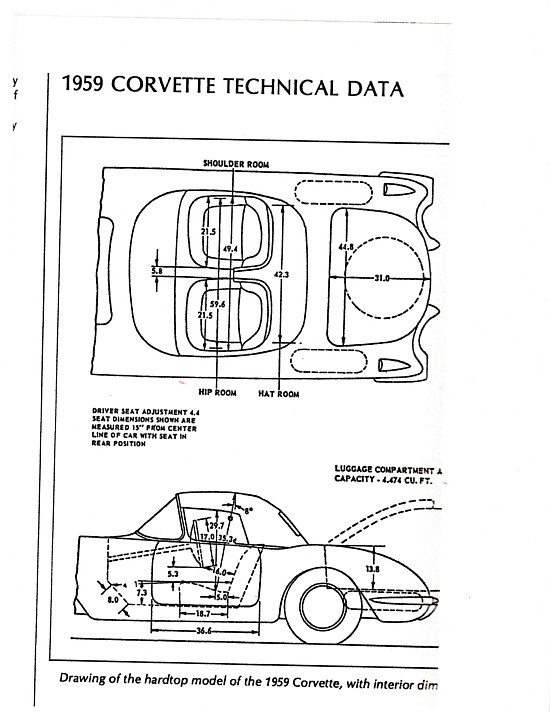
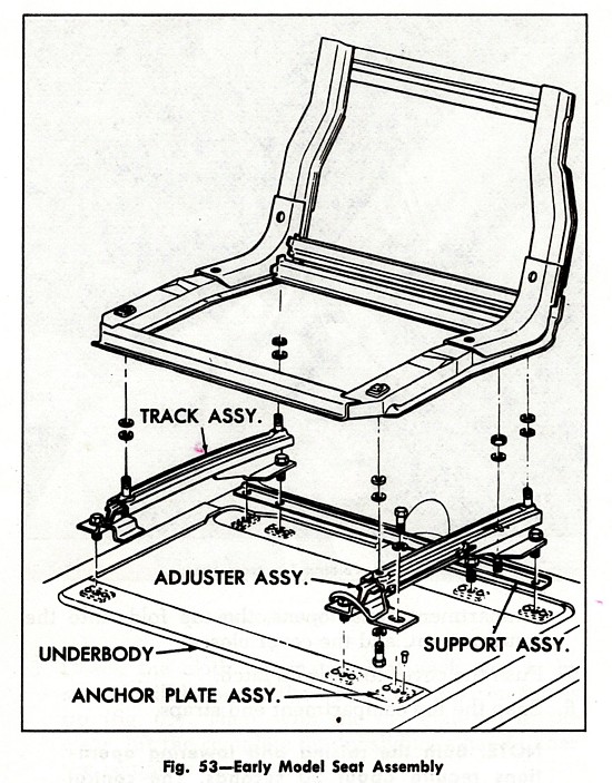
**********
05/27/2021
I’m redoing the front suspension on my 1960 (5034).  My question is should I leave the original inner upper pivot shaft?
What I have read it is the most important part of the job.  The new cap only goes on a few rotations and bogs down, the
old caps spin right on.  What I can figure is it is a 3/4 by 11 can’t find a die to clean threads.  Also read where you
can make the tool to thread new pivot shaft in with old shaft parts but see Paragon part number 10538 is a pivot shaft installer,
is that for this pivot shaft?  I called their tech line and the guy was what does the catalog say, it doesn’t.  Thanks
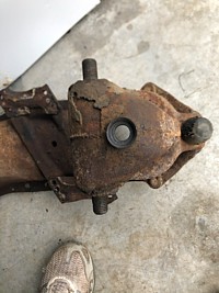
From: Verle Randolph, Red River Chapter VP:
Are the new caps the same thread pitch? Your description suggests wrong
thread pitch.
I cannot tell from the picture, are threads damaged? Are they rusty or
encrusted with dirt, etc?
You can clean threads with a wire brush without damaging them. If they are
damaged on the starting end I have cleaned large threads like that with a
triangle file and carefully working to make them match with the good
threads.
Verle
From: Joe LeMay, SoCal Chapter Advisor:
Examine the threads on the shaft and you should find there is wear. That is why
the new nuts do not fit. Understand how this works. As the suspension
compresses and the A arm moves, the end nuts rotate. If they are worn, it may
have play.
Getting the new upper inner shaft installed takes a lot of force. I stood
on a breaker bar to get the shaft to turn until equal amounts of thread are
showing on both sides. If the fitting weld lets go, a new one will need to
be welded in.
That installation tool is not useful. I have one that I did not use. I
used the lower outer shaft as a tool. The bushing and pivot bolt are the
same thread as the upper inner shaft. Put the bushing on the outer shaft
threads, screw the pivot bolt into the bushing until it contacts the end of
the shaft and you have a tool to screws the shaft in with.
From:
John Spencer, Red River Chapter Advisor: If the old caps (nuts) thread
on with no resistance but the new ones do - the new ones are of the wrong
thread. Don't force them. Have you purchased a new pivot shaft yet - try
the new nuts on the new shaft. If the new shaft threads are different, they
will not install in your original equipment.
**********
05/01/2021
In 1983 I purchased a garage-fire Corvette which was located just a few blocks
from Noland Adam's home in Albany, CA. I really got into rebuilding it at the
time, joining the Bay Area chapter of NCRS. My wife and I even hitched a few
rides down to the meetings with Noland. Here it is, 2021, and after a stock car
racing period, during which time the Vette just
sat,
I got back to work on my "driver" several years ago. The burned car left me an
almost original chassis, engine, T10, and the original hardtop. The car is about
95% complete but one thing that bugs me is that the hardtop lines up with all
connection points except for one on the deck lid, it's about 3/8" off and I can
see no way to make it fit. The body that we used came from a Corvette wrecking
yard in Yuba City, CA. Noland likely remembers it, although it's long gone
today.
So the body is not the one that the original hardtop was mated to. This could be
the main, or the problem. Does SACC have any ideas about this, or
heard of any fixes?. I can only think of plugging the hole and drilling a new
one. Anything would be appreciated. Thanks,
Joel
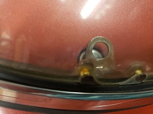
From: Verle Randolph, Red River Chapter VP:
Joel,
Measure the hole locations on both sides on the deck lid. I assume the
deck lid is lined up well with the body.
Hard tops will can and will distort if they are not stored with the
right supports.
I suspect you can move that part of the hard top over enough to get the
bolt in. Make sure the other bolt is not tight and try to push the
misaligned part into place. You push and hold while wife starts the bolt.
You may have to release the latches on the front to get the back started
then latch the front.
Don't ask how I learned about the hard top "warping".
Verle
**********
04/25/2012
Any thoughts on Needle bearings on King pins.
Found info on the web. [ A king pin kit with a Torrington needle bearing ]
Replaced Kings Pins years ago, that were frozen in place.
Had to Heat the H out of the spindle to get the old ones out of My
1960 C1, serial number 100
JOHN
From:
Verle Randolph, Red River Chapter VP:
I installed needle bearings in my 57 about 2001. Over the last 20 years we
have driven it over 40,000 miles, most of that on long road tours with no
problems.
I have been diligent in greasing all 22 front suspension zerks about every
1000 miles including on road tours frequently at oil change shops. I have
always insisted in going into the pit with the worker so I could point out
all the zerks.
Verle
**********
04/14/2021
Hi,
I am I the process of fixing my car. I could really use
some help applying the dash pad. Any suggests or someone who knows how to do
this?
Frank
From:
John Spencer, Red River Chapter Advisor: Corvette Central and Al Knoch
Interiors offer DVDs that show how to do this. There are also U-Tube videos
available, if you search C1 Dashpad Installation
**********
04/08/2021
In
September
2020, your officers answered some questions about speedometer
cables and bouncing speedometer needles on my 1959. I also searched your posts
for information on removing my speedometer and tachometer. I have all the wires
labeled, bolts removed but can’t figure out how to remove the wiper cable pull
knob on the instrument panel. Please advise. Thank you.
Eric
From:
Bill Huffman, Michigan Chapter Advisor:
Eric,
to release the switch from the cluster housing.
Good luck,
Bill Huffman, Pres.
Michigan Chapter SACC
From:
Larry Pearson, SoCal Chapter Advisor:
Eric: Disconnect the battery. Then you reach up and disconnect the
speedometer and tachometer cables. Remove the 1/4 inch bolts that hold the
instrument housing to the dashboard structure. Pop out the instrument light
bulbs in the speedometer and tachometer. The oil pressure gauge is a
mechanical gauge with a copper line connecting it to the engine. Be careful
not to damage it. You probably will have to remove the screws holding the
Ammeter/Oil Pressure gauge from the instrument housing. Put a thick towel
over the steering wheel hub to protect it. Pull the instrument housing
forward as much as possible so you can access the screws holding the
tachometer and speedometer to the instrument housing.
The wiper control is a twist knob, not a pull knob. Loosen the set screw
and remove the knob from the control shaft There is a hex nut holding the
wiper control to the instrument panel. Remove it with a socket and the
control comes loose from the instrument housing.
Larry Pearson
Addendum
from Larry Pearson, SoCal Chapter Advisor:
Bill Huffman made a good point that I forgot. I now recall that the wiper
control is not held on by a hex nut, but with a round nut with two slots.
You don't need a special tool to remove it, you can improvise by using long
nose pliers. Grind the tips as necessary to fit into the slots, and use the
plier's handles to turn the nut.
Larry Pearson
**********
03/29/2021
Was wondering if you could tell me if
you can “interchange” channel selector “push buttons” from a 59 to a 62 Corvette
Wonderbar radio. I have a 62 radio I need to make look like a 59. I understand
the push buttons are made differently. Also, are the “Chrome Face Plates”
interchangeable? Thanks.
Dennis.
From:
John Spencer, Red River Chapter Advisor: Ecklers Corvettes
800-327-4868 sells faceplate/bezel/pushbutton refurbish kits for 58/60 and 61/62
Corvette wonderbar radios. Contact them to see if they are mechanically
interchangeable.
From
Bill Huffman, Michigan Chapter President: Dennis,
Wonderbar knobs, push
buttons & faceplate are different between 1959 and 1962 radios but functionally
are all the same. Kits to convert or restore are commercially available from
most Corvette vendors.
The link below is from Corvette Central so you can see
what's available.
https://www.corvettecentral.com/c1-53-62/radio/radio-rebuild/1959/?count=15
Good luck with your project,
Bill Huffman, Pres.
Michigan Chapter SACC
From:
Larry Pearson, SoCal Chapter Advisor:
Dennis. The 1958-1960 Corvette Wonder Bart radios are the same and have
flat ends on the push buttons, The 1961 radios are the same as the 58-60
radios, except that the button faces are rounded. The 1962 Radio was a
completely new design. The case is larger and the large aluminum filter
capacitor was moved from the left side to the rear of the unit. From 1958 -
61, the large aluminum filter capacitor on the left side had a tendency to
interfere with the cowl vent actuator mechanism and was easily damaged by
it. The face plate and buttons on the 62 radio have the same appearance as
the 1961 radios. The wonderbar switch on the 62 radio has a different feel
to it when actuated. Instead of the microswitch click-click feel as it is
depressed, it has simply a smooth push connection feel when activated. The
face plates of the 1958-62 radios all look the same and are easily removable
and are interchangeable, but that is not what you need. The push button
assemblies are integral to the internal tuning mechanism and would be
extremely difficult to remove and interchange. Find a 58-60 radio and do a
swap with someone who needs a 62 radio. I have a 1960 radio and need a 1962
radio.
Larry Pearson
**********
03/27/2021
I have a 1962 corvette that to the best of my knowledge has a 1962 block and
a1963 transmission.
I recently had a new clutch and throwout bearing installed.
Since then the car drives differently. first the clutch pedal has to be
depressed to the floor to shift, which was not the case before the work.
The clutch pedal would actually get stuck to the floor if it was depressed
that far before the replacement.
The concerning thing is that the car shakes (jumps) when in gear (all gears)
when driving down the road, It will now when coasting with the clutch pedal
pushed or when accelerating.
Is there adjustments to be made?
Greg
From:
Verle Randolph, Red River Chapter VP:
The clutch to the floor "should" be just an adjustment of the linkage. If
that does not cure that problem then who ever installed the new parts needs
to make it right.
You say the car shakes in all gears. Does this happen at a certain engine
RPM or does it happen at a certain speedometer reading?
If at engine RPM that suggests something related to the engine is out of
balance, such as the new clutch that was installed.
I have had several new pressure plates/clutch disks significantly out of
balance. Started having them balanced as a matter of course before
installing. I remove flywheel, which is a known good part and have the new
clutch balanced on the flywheel.
Verle
From:
John Spencer, Red River Chapter Advisor: The clutch pedal travel is adjusted by
lengthening / shortening the clutch push rod (847) that connects the cross shaft
(709) to the clutch wishbone.(489K). This is accomplished by screwing the push
rod clevis (883) up or down the rod. See attached drawing for reference
numbers. The shaking can be several things. If it didn't shake before you had
the work done, it shouldn't shake now. If the clutch assembly (Disc and/or
pressure plate is out of balance that will cause a shutter, but most replacement
parts don't require balancing. The crankshaft where the pilot shaft of the
transmission is stabbed has a brass bearing or bushing. If this was
inadvertently removed and not replaced - you will get a violent shaking at all
speeds and gears (common oversight).
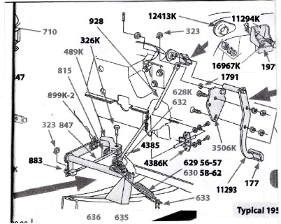
From:
Larry Pearson, SoCal Chapter Advisor:
Greg: You need to consult with section 6R, "Clutch", of the Corvette
Servicing Guide, Publication ST-12, which is the only official shop manual
for C 1 Corvettes and is a "Must Have" for C1 owners. If you don't have a
copy it can be purchased from any of the major Corvette parts suppliers. By
reading Section 6R, you will learn a lot about how the clutch system works
in your car and how to make adjustments.
Whenever changing a clutch, the clutch free travel must be adjusted. This
procedure is found in page 6R-3 of ST-12. Normally, clutch free travel is
about 1" before the clutch linkage starts to disengage the clutch. If it is
too much, you will have to push the clutch pedal too far to disengage the
clutch. If it is non-existent or worse, the clutch can slip all the time,
and you will burn it up. Maybe you installed a throwout bearing of the
wrong length. If so, adjustments won't fix it. Your car originally came
with a Borg & Beck style pressure plate. Maybe someone put in a diaphragm
type pressure plate, which your car is not set up for.
Clutch pedal total travel adjustment procedure is given on page 6R-3. It
sounds like this may need adjusting. Normally, changing a clutch and
throwout bearing does not affect this adjustment.
Clutch pedal repositioning adjustment is given on page 6R-3 to 6R-4. It
sounds like this may need to be adjusted. Normally, changing a clutch and
throwout bearing does not affect this adjustment
If you paid a mechanic to do the work, the result you describe is totally
unacceptable, and you should take the car back to have it fixed. Because
your mechanic may be totally unfamiliar with vintage Chevys, you should take
your ST-12 Manual with you. Your car is probably older than your mechanic.
Maybe, you too.
Larry Pearson
Also
from John Spencer, Red River Chapter Advisor: Greg - you casually
mentioned your clutch would stick when pressed to the floorboard. This may not
have been your major concern, but it is a problem that needs addressing, so here
goes. This can be caused by several things. See
the attached illustration: The return spring (630) on the cross shaft (709) is
designed to give resistance to the pedal when you clutch. As you continue to
depress the pedal, this spring crosses the axis of the cross shaft and becomes
an assist rather than a resisting force. This is designed to allow you to relax
a little when holding the clutch in at - say - a stop light. 1) If your
clutch pressure plate springs are weak they may not overcome the return spring
on your cross shaft, however, they would have to be very weak to cause this. If
this is your problem - replacing the clutch should solve this. More likely 2)
the clutch return spring (630) attached to your cross shaft (709) is the
problem. Where the spring changes from a resisting force to an assisting
force, as you depress the pedal, is adjustable. The adjustment is made with
the bracket (635). It should never cause the pedal to stick down. Several
things may cause this 1) You have the wrong return spring (630). This spring
should be a 17 coil spring. 2) the return spring (630) attaches to the cross
shaft bracket (635) by a link (636) which is about 1" long. If this link is
missing and the return spring (630) is connected directly to the bracket (635)
it requires the return spring to be stretched further than it is designed to be,
and will significantly increase its tension strength. When the clutch is
depressed to the point the return spring becomes an assist, the increased pull
on the spring may become more than the pressure plate springs can overcome, and
could cause the clutch to fail to return properly. Check to verify you have a
correct return spring and the attaching link is there. Good luck - John
**********
03/25/2021
Hello, I recently placed the body onto a new frame. I did not personally
remove the connections under the hood. Can you direct me to a schematic showing
the connections and grounding straps for the 1962 corvette.
Regards Mark
From:
Larry Pearson, SoCal Chapteer President:
Mark: The schematic for the 1961-62 Corvettes is shown on page 12-14,
Figure 19, of the official Chevrolet service manual for all C-1 Corvettes,
Corvette Servicing Guide, publication ST-12. If you don't have a copy, it
is a "must have" for all C-1 Corvette owners, and is available in reprint
form from all major Corvette parts suppliers. You also need a copy of the
Corvette Assembly Instruction Manual (AIM) for the 1962 Corvette, which
tells how the entire car was assembled, and is available from the same
sources as ST-12. Page B 146-147 shows how the wiring is routed under the
hood. By paging through the AIM, most of the questions you might have will
be answered.
As far as grounding goes, all electrical systems must be grounded to the
engine block, which is connected to the negative side of the battery. The
frame is not a good ground. Because the fiberglass body does not conduct
electricity, every lamp and electrical component in the car must have a
separate ground wire that ends up going to the main ground wire for most of
the car's electrical systems, which is a 12 gauge black with white stripe
wire, which is connected to the driver's side upper rear rocker arm screw.
This must be there, and in good condition, or nothing works. In addition,
the radio has its own ground wire, which connects from the 1/4-20 bolt that
connects the radio to the support bracket and goes through the firewall to
the passenger side upper rear rocker arm cover screw (see ST-12, page
13-3). The wiper motor also has a separate ground wire that connects its
mounting plate to the same rocker arm cover screw as the radio ground (see
ST-12, page 12-5, figure 5). The voltage regulator case is grounded to the
engine block via the woven shield that encompasses the generator field and
armature wires. It connects to a screw on the generator housing, which
connects electrically to the engine block.
If your car has a radio, there are two heavy woven copper ground straps that
connect each side of the front engine mount to the frame (see ST-12, page
13-7). This makes the frame a "ground Plane" for the radio antenna for
improved reception, which is also grounded to the frame in the trunk (see
ST-12, page 13-4). There are also filter capacitors on the generator
(connects to the armature terminal), the voltage regulator, and the ignition
coil, designed to filter out electrical noise in the radio (see ST-12, page
13-5, figure 4).
Larry Pearson
**********
03/09/2021
Hi
Thank you for the information on the windshield wiper bracket mount on
my 58. I had read that it was in that location for the fuel injection cars
but wanted your input to confirm.
My follow up question is did they put the mount/bracket on cars that did
not have the wiper sprayer option ? My car has no sign of sprayers but has
that bracket with no tank.
Thank you again
Barry
From:
Larry Pearson, SoCal Chapter Advisor:
Barry: This is very interesting. The windshield washers were an option in
1958, and maybe your car was ordered to delete that option and the factory
mistakenly bonded an inner fender for FI and washers to your car. That
bracket was screwed to the inner fender before the inner fender was bonded
to the outer fender, because it was much easier to do it that way. If you
remove it, there is no paint under it. Either that or someone removed the
sprayers and filled the holes. Look under the dash for evidence of this.
Or maybe your car was wrecked and a FI front end with washers got bonded
on. There are endless possibilities here.
The presence of this bracket does not, in itself, prove that your car is an
original FI car. If it is, there is a rectangular nut plate riveted to the
driver's side inner fender for mounting the FI air cleaner. This was also
attached to this inner fender before the inner fender was bonded to the
outer fender.
If it turns out that your car is a washer delete and you are restoring it to
be judged, you should remove the bracket and fill in the holes. Also, there
was a large cylindrical vacuum storage tank mounted to the inner fender
above the battery on washer equipped FI cars. Is that there?
Larry Pearson
**********
03/07/2021
I have a 1959 corvette and am trying to install
the rear bow weather strip. The weather strip has 2 sets of two holes at
the latch positions, does the latch fit over the weather strip and the
screws go thru it or are the holes in the weather strip just access holes to
reach the latch screws. Also is there a trick to getting the weather strip
lip to stay on the rear bow so it can be glued or stapled?
From:
John Spencer, Red River Chapter Advisor: Order of assembly - top bow -
weatherstrip - latch - mounting screws. See illustration below.
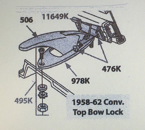
**********
03/04/2021
Hello, I’m restoring a 1960 barn find. Finally putting the
car back together. However, I need some direction on how to install the new dash
pad.
I know that I need to cut the dash but not sure how much
too cut and where. If there is any help or a source you can point me to I would
greatly appreciate it.
Thank You, Bob
From:
Bill Huffman, Michigan Chapter Advisor:
Bob,
Here is a
link to Part 1 of an 18 part YouTube video from Paragon Reproductions that
shows the whole process.
Good luck
but remember, measure twice and cut less than you think you should.
You can
always trim twice but once cut too short, you buy a new pad.
Bill
Huffman, Pres.
Michigan
Chapter SACC
**********
03/01/2021
61 corvette fi yes but not on car ign switch wont start car head
lites dont work battery good put no power to ign switch and head
lites found a wire in same harness with the purple wire that goes to
sol had all coating burnt off cant tell what color that wire was
not sure where it went but all wires are on the ign switch
From:
Bill Huffman, Michigan Chapter President:
Tom, you
need a GM 1961 Corvette Assembly Manual that can be bought online.
You are
also going to need almost a complete re-wire so he is going to need Paragon
Reproductions or Corvette Central
where he
can also buy an assembly manual to do the repairs.
Most of
the electrical info & schematics are in their catalogs or with Lectric
Limted's wiring harnesses.
Bill
From
John Spencer, Red River Chapter Advisor: CAUTION - CAUTION - CAUTION
: Burnt insulation usually means YOU HAVE A SHORT in your wiring.
Electrical shorts and fiberglass Corvettes don't play well together. Before
you go any further - make sure you have a fire extinguisher readily
available. If you don't - Go Get One. Next thing you need is a volt meter
- you don't need an expensive one - just one that will tell you you have 12
volts at test points. Third - its a good ides to have a helper, operating
the ignition switch and testing for voltage in the engine bay or under the
dash by yourself is difficult. I have included a rough layout of the wiring
(ignition / lighting circuit) for reference, assuming your car has a stock
harness.
Before you start - loosen the connection to your battery sufficiently -
so you can disconnect it immediately if needed.
1) Power comes from the battery - to - the starter solenoid (term B) -
to the Ammeter. (SEE DIA FOR WIRE SIZES AND COLORS)
2) From the Ammeter - to - the Ignition Switch..... and..... Lite switch
.... Clock, Horn Relay, ACC Fuse, Voltaqge Reg, and Cigarette Lighter
Connections (connections are NOT fused).
3) From the Ignition Sw. - power is returned to the Starter Solenoid
(term S) to activate the solenoid and connect the battery to the
Starter.
TESTING FOR PROBLEM
1) verify voltage (12V) at the "B" term of the solenoid. (ignition
off) This is the 6 GA wire off the battery.
2) the Black 12 Ga. wire from that same terminal feeds the Ammeter. The
load side of the Ammeter feeds the Ignition Sw (14 RED) and the Light
Sw.(12 / 14 RED) and others.
Since you have noted a burnt wire in your starter harness it is probably
the wire running from the solenoid to the ammeter. This would
disconnect power from the ignition and lights.
3) Test for voltage on the Ammeter. Single wire is feed (probable burnt
wire) - multiple wires is load. Both should have 12V (ignition OFF).
If no voltage - you have verified the main wire from the solenoid to the
ammeter is open (burnt). Note: This is not your problem, however, it is
the result of a problem. Analyze the wire from the burn to the
ammeter. If you don't find an obvious problem - disconnect the battery
and run a new wire (12 Ga.) to the ammeter. It would be a good idea to
put a fuse in line with this wire until you have everything working
properly. Get a hand full of fuses also. Once the wire is in place -
reconnect the battery. If the temp. wire (fused) to ammeter blows,
disconnect all wires from the load side of the ammeter. Reconnect them
one at a time - disconnect battery / connect single load / reconnect
battery. Does one blow your fuse ? If so that circuit has the short
you are looking for. All these feeds are hot (they do not require the
ignition switch to be activated) except the ignition switch feed. When
testing the ignition circuit the "ON" position connects the instruments
and radio. The START position connects the power to the starter
solenoid.
Once you have identified what circuit (load) is causing the problem, you
simply have to determine if the wire feeding the load is the problem or
the load itself. Good luck.
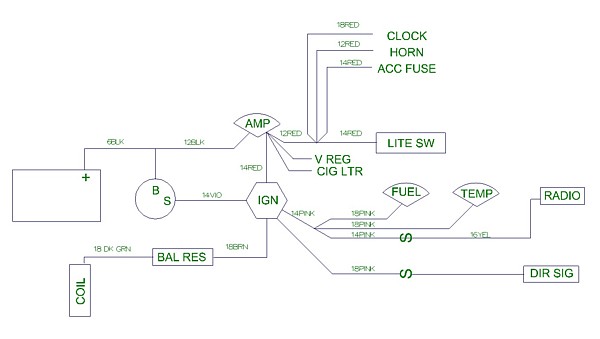
From:
Larry Pearson, SoCal Chapter Advisor:
Tom: If you understand electricity and know how to use a Multimeter
(measures voltage and resistance), you need to consult with the schematic on
page 12-14 (Figure 19) in Corvette Servicing Guide, Chevrolet publication
ST-12. This is the only official shop manual for C-1 Corvettes and copies
are available from all the major Corvette parts suppliers.
If the wiring harness is burned up, you may have to purchase a new wiring
harness for the firewall forward. This wiring harness connects the battery
to all the circuits in the front of the car, including the ignition,
headlights, generator, voltage regulator. horn relay, front turn signals,
starter solenoid, windshield wiper, and more. The purple wire goes to the
starter solenoid and is part of this wiring harness. It sounds to me like
the large red 12-gauge wire from the starter solenoid may not be properly
connected to the large starter lug where the battery cable also connects.
This wire provides battery voltage to all the electrical circuits in the
car. Also, the engine block is the ground point for all the electrical
circuits in the car, and everything connects to a driver's side upper rear
rocker arm cover screw via a 12-gauge black wire with a white stripe. If
this isn't connected, nothing in the car will work.
Without seeing the car, this is all the advice I can give you at this time.
Larry Pearson
**********
02/18/22021
On a 56 Corvette with 2 four carbs, and 1896
heads, Is the generator pulley 3 3/4" or 3 5/8" also are the press marks
rectangular or round? my 56 is #1896 Thank You
Wayne
From:
Joe LeMay, SoCal Chapter Advisor:
Hi Wayne
The correct heads are at that VIN would be 762 and used with the 3 bolt
exhaust manifolds. The 043 generator uses a 3 5/8 pulley. What are press
marks referring to?
Joe
**********
02/18/2021
I have a question about door weatherstrip
installation. The reproduction weatherstrip that I recently bought for the doors
on my 62 has the plastic pins to insert in the holes of the door....so I would
like to know is it necessary to use 3m adhesive when the pins and clips might
suffice? Thank you , Garry
From:
Bill Preston, Red River Chapter President:
Yes!! Use the 3m adhesive. Put a THIN layer of the adhesive on both surfaces as
it is a contact cement.
Allow dry til it's slightly sticky to the touch before putting the
weatherstrip onto the door surface.
Don't close the doors for at least 24 hours after applying the
weatherstrip to the doors.
**********
02/09/2021
Hello,
My 1956 air cleaners have a lot of scratches and some
dents. Should I have then restored or just buy replacements? I don't plan to
have the car judged, but I always do like to keep the original equipment if I
can. Expense wise I would just purchase new ones if it was going to be real
costly to restore the originals. If I were going to have them restored, is
there anyone that you can recommend to me to do that job?
Also some time
ago I asked the question of why my two clutch forks that I had put away to use
in my 1956 when I finally got to it, were different. One with a slotted end and
one with an oval hole. You explained the the slotted one was used in a 1957
through 1962. I think that you went on to say the the adjustable ball, held on
with a clip, are hard to find. I do have the complete unit and I wonder which
style you would recommend that I install.
Thank you,
Michael
From:
Larry Pearson, SoCal Chapter President:
Michael: I assume that you are referring to the small sealed aluminum air
cleaners. These air cleaners are made up of a thin aluminum stamping.
Once it gets dented, the metal stretches and it can't be simply be pushed
out from the inside without leaving an unsightly ripple. And there is not
enough metal thickness to buff out deep scratches. In other words, they
cannot be restored to the original look if they have dents and deep
scratches. This is also true for the 1958-62 large aluminum air cleaner
tops. If you want the original look, you must buy the reproductions.
Larry Pearson
From:
Joe LeMay, SoCal Chapter Advisor:
Hi Michael
I would use the factory typical configuration for a 1956. It is easier to
get it correct the first time rather than later on.
Joe
**********
02/08/2021
Hi,
I recently bought a 62 Corvette the wipers do not work? No hum from
the motor cables seems to be in tack how do I tell if it is the transmissions or
the motor?
Thankyou
Bob
From:
Bill Huffman, Michigan Chapter President: Bob,
Welcome to Corvette
heaven. I'm guessing you just bought either your first Corvette and or your
first C-1.
The tach drive is off your distributor and has nothing to do
with your wipers.
If the tachometer is noisy, it's probably your tach cable.
If it's noisy & erratic, it could be either or both of the tachometer or
cable.
The electric wiper motor switch is on top of the wiper motor
gearbox and is actuated by a pull cable attached to the wiper switch located on
lower left of the instrument cluster closest to the steering column.
The
problem could be switch cable adjustment or being disconnected, a blown fuse or
faulty contact inside the gearbox switch. Use a meter to check for electric
current. If you have WS Washers, the coordinator which mounts on the gearbox
switch plate could be missing, broken or disconnected. Try buying an original
and you'll see why it could be missing.
The wipers don't have
"transmissions", they have a mounting Pully-Shaft and are both driven by cables
off the wiper motor gearbox.
Buy yourself a 1962 Corvette Assembly Manual and
read it before you
accidentally break something that is costly to replace.
Congrats on your new toy,
Bill Huffman, Pres.
Michigan Chapter SACC
From:
Larry Pearson, SoCal Chapter Advisor:
Bob: Things to check:
1. Is the control on the dash actually moving the switch on the top of the
motor? The connection is adjustable with a set screw and washer. All 62's
came with a windshield washer, and the vacuum operated automatic activator
is on top of the wiper motor connects to the motor switch and maybe this is
keeping the motor from operating.
2. The motor gets its electrical ground from a brown wire that connects the
base through the right mounting screw to the upper rear rocker arm cover
screw on the right bank. The motor needs this ground connection, otherwise
it gets its ground through the control cable that goes to the dash, and this
is not a good ground connection. The engine block is the ground point for
all electrical systems in the car. The car body is non-conductive
fiberglass and all electrical systems on the car must have their ground
connections end up on the engine block. The frame is not a good ground.
3. The wiper motor gets its power through the ignition switch brown wire
that connects to the ignition ballast resistor on the passenger (right)
side. Is it there, or is it going somewhere else?
4. If you have an ohmmeter, check the resistance of the power lead to the
motor case while moving the switch. It should read less than one ohm when
the switch activates the motor. If you get an open circuit no matter where
the switch is, then the motor needs repair. Corvette Central has a
rebuilding service. Or you can open up the cover and see if there is a
broken wire and maybe fix it yourself.
Larry Pearson
Bob: Some additional thoughts on your wiper problem:
1. The wiper motor circuit is not fused. It comes directly off of the
ignition circuit, which is not fused. There is a built in circuit
breaker that protects the ignition circuit against internal shorts in
the Wiper Motor.
2. Complete servicing information for the windshield wiper motor and
system is contained 12-4 through 12-9 in Corvette Servicing Guide,
publication ST-12. This is the only official shop manual for all C-1
Corvettes, and is something you must acquire to help you maintain your
62. It is available from all Corvette parts suppliers. Page 12-9
contains a Trouble Shooting guide for the wiper motor.
Larry Pearson
From:
John Spencer, Red River Chapter Advisor: First - the wiper motor operation
has nothing to do with the wiper transmissions and drive cables. Don't tear
into these unless you have to. The motor control located in your dash is not
electrical - it is connected to the wiper motor via a sleeved cable. The actual
electrical switch that turns the motor on and off and controls its speed is on
the motor assembly itself. 1) Make sure you have power to the motor. The motor
feed connects to the ballast resistor in the engine bay on the firewall on the
passenger side by the wiper motor. This is not a fused connection. It feeds
directly from the ignition switch. Switch ON = 12V. With the switch ON you
should have 12V at the ballast resistor and wiper motor. 2) Make sure the motor
is grounded. It should be a jumper between the motor mounting plate and the
engine valve cover mounting screw. 3) Make sure a twist of the wiper switch on
your dash moves the wiper motor actuator slide. And moves it far enough to
activate the motor switch inside the cover plate to which it is attached. 4) If
the actuator doesn't move or you are not sure it moves far enough - loosen the
clamping screw that holds the cable jacket in place and move the actuator by
hand. If after this you get no motor, you probably have a bad motor. You can
disassemble the motor assembly and remove the cover plate to inspect the switch
and speed controls, but I have rarely seen them fail. Good Luck - John
**********
02/07/2021
Hi
Is this a windshield washer tank mount ?
Passenger side wheel well.
Thanks
 From:
Chip Werstein, SoCal Chapter President: Barry
From:
Chip Werstein, SoCal Chapter President: Barry
The passenger side washer jar
was used on 58 thru 62 fuel injected cars and your bracket is unique to fi cars.
All others used a diffetent bracket mounted on the drivers side splash pan. The
fi washer equipment was moved to the passenger side due to air cleaner
interference.
Chip Werstein
From:
John Spencer, Red River Chapter Advisor: Yes!!
From:
Larry Pearson, SoCal Chapter Advisor:
Barry: Yes it is and it is mounted on the passenger side because your car
was originally fuel injected. On 1958-1962 fuel injected cars, the air
cleaner assembly blocked access to the left hand location, so it was moved
to the passenger side and uses a different type of bracket. Also, because
it is close to the exhaust manifold, a black painted aluminum heat shield
was screwed to the inner fender with three screws to protect the washer
assembly from the heat. The drivers side mounting for carburetor engines
was mounted low on the fender skirt and therefore was not subjected to
exhaust manifold heat,
The windshield washer was and extra cost option until 1962, when it became
standard equipment.
Larry Pearson
**********
02/02/2021
Restoring a 1960 (5034), I have the doors off and can't find any video or
how to on tearing down the doors, removing windows ect. I have an assembly
manual but not very helpful on how to strip everything out.
thanks
From:
John Spencer, Red River Chapter Advisor: I have taken Um-teen doors apart
and I have to retrain myself every time. They are kinda like a Chinese
Puzzle. Just take your time and don't get frustrated. To take the
window out you don't have to remove the front post and door guts, a lot of
rebuilders do - it just adds to more loose pieces you have to manipulate.
You roll the window up and down to gain access to all the mounting hardware.
1) With the glass (and frame) loose from the regulator (four small screws hold
the glass to the track that runs along the bottom of the window unit) - 2) Lower
the regulator down out of the way. 3) Rotate the window assembly slightly toward
the rear (front up - back down) and it will come out. If it binds up -
don't force it. Move or remove what is binding. With the glass out,
the remaining pieces come out fairly easily. When you're re-assembling it
- go slow - pay attention to how it came apart. The glass and frame go in
last. The door glass frame is notorious for catching on everything.
You will think it won't go back together - inspect the back glass frame - it
will undetectably catch on the door braces and not allow you to set the window
forward enough, thus the window will not roll up and down when assembled.
Note the operation of the window as it rolls down - it rocks back then down.
Good Luck. Let me know if you invent any new words, I'll add them to my
garage dictionary. - -John
**********
1/17/2021
My name is Leo.
I inherited my uncles 58 corvette about 1.5 years ago and I’ll be starting restoration.
First thing first. Fiberglass work. I already had a fiberglass guy look at my car and seems to be on point with the work needed,
(front end needs the most work). He looked at the top of the front end, fenders and hood. The fiberglass is solid,
but has fibers exposed.
My question to you concerns the process only for the top of fenders and hood. I was told to sand and reglass using chop Matt sheets.
I was also told to sand and mix resin with half inch chop strand (the half inch chopped fiberglass that comes in plastic bags-looks
like powder) and brush a new layer over the tops of the fenders and hood.
Then block sand. Is this something that is done? It was suggested because the car sat out for 10-20 years in a field, and even
though the fiberglass is solid, the top is showing fibers. What’s your thought?
Thanks
Leo
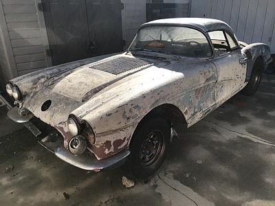
From:
John Spencer, Red River Chapter Advisor: Leo - if the glass is sound, and
it looks like it is, I would just restore the gel coat. This is a spray on
process, it doesn't add significant thickness and it will give you a smooth
surface to prime and paint. You will still want to lightly sand the gel coat
(300 grit or higher) before priming.
**********
1/5/2021
Hi,
I
have the rear axle strut rods off my 61 and would like to replace
the bushings. Does anyone have any experience doing this? I got
replacements from Corvette Central, they said just use WD40 or soapy
water and just "push them into place". It sounds to easy.
Thanks, Mike
From:
Bill Huffman, Michigan Chapter Advisor:
Mike,
When
you're done, the rebuilt strut rod assembly with 2 new bushings needs to
look exactly like what you started with except, it will look & function as
"new".
That
means the bushing steel outer ring & the steel inner ring both need to be
centered in the strut rod ends after assembly even though inner & outer are
of different length.
Whether
you use a mechanical press, a hydraulic press or a big vise for assembly,
that means you need to use spacers on both sides to apply pressure to the
rod end O.D. emboss on one side and to the bushing outer ring on the other
side when pressing them together.
The outer
bushing is a press fit into the rod end, so lube of some type will be
necessary.
Good
luck,
Bill
Huffman, Pres.
Michigan
Chapter SACC
From:
Chip Werstein, SoCal Chapter Advisor:
Mike
Bill's explanation is correct but the bushings can still be
difficult to press in. To make installation easier i heat the strut rod
ends....im in s.cal so just putting them in the
sun
on a warm day does the job......and put the bushings in the freezer. The rod
will expand and the bushing will contract providing a couple thousands extra
clearance which will make installation much easier.
Chip Werstein
**********
Hi
I have noticed the the attached photograph is different then just about
every other 58 Corvette I have seen
Can you identify the difference for me ?
Barry
From:
Joe Lemay, SoCal Chapter Advisor:
It is a vacuum wiper motor. I had one in a 55 Chevy. They are a bit of a
problem going uphill in a downpour; stopped.
Joe
From:
Chip Werstein, SoCal Chapter Advisor:
Barry
As Joe said, you have the wrong wiper motor. Should be electric.
Also the ballast resister is in the wrong location.
Chip Werstein
**********
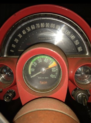
Hi
I have read about some tachs but haven't found any comments on redline at
5500 and what it may have been originally attached to 230 hp I am guessing.
The other redlined higher at 250 and 290
Thanks
Barry
From:
Bill Huffman, Michigan Chapter President:
Barry,
For 1958 thru 1960, the 5500 RPM tach was used on the low HP engine
options which were the 230 HP carbureted,
245 HP dual carbureted &
250 HP w/ FI.
The 6500 RPM tach was specified for higher HP options 275
HP dual carb and 290 HP w/ FI.
Good luck with your restoration project,
Bill Huffman, Pres.
Michigan Chapter SACC
From:
John Spencer, Red River Chapter Advisor:
This is not a 58 tach. 58 tachs had a rev counter (like spedo has a mileage
counter). This tach appears to be a 60 model. "light green background to 20 -
signal green above that.
From:
Chip Werstein, SoCal Chapter Advisor:
Barry
The tach in your photo is from a 60 to 62 low horse car. Normally
referred to as a 5300 redline. 58 tach had no color band up to the redline, dots
under the numbers and a rev counter. These were used on 230,245 and 250 hp cars.
Chip Werstein
**********
12/17/2020
Hello,
I purchased from a friend a harmonic balancer with a
riveted on pulley, which is about 6 13/16 inches across and my water pump
pulley is 2 3/4 inches high from the inside to the outside of the pulley. The
pulley is 7 1/8 inches across. I was taken off his 265 cubic inch engine. I
began by installing a new crankshaft spacer recently purchased from Corvette
Central. i put some RTV silicone on the inside of the balancer, (recommended by
the machine shop that rebuilt my engine), and installed the balancer. It slid
on 1 1/4 inches, the length of the remaining part of the crankshaft sticking
out. My water pump was also recently purchased from Bill Mock. My water pump
pulley has about 1/8 inch of clearance between it and the balancer pulley,
looking at it from the front and from the side it looks like the balancer pulley
is slightly behind the water pump pulley. Does that all seem correct?
The next question is in regards to my core support that came with my car, a
basket case without a radiator. When taking the car apart a few years ago, I
found that the core support had a hole cut out in the bottom by a torch. Most
likely for a radiator drain cock. Thinking that it was pretty ugly, I took it
and a later solid axle core support to a shop and asked them to cut the drain
hole from the later one and weld it into the support from my 1956. Eventually i
found a radiator and when i slid the radiator into the core support, I found
that the drain is well above the drain hole that I had installed. Looking on
the 1956 assembly manual it looks like the 1956 core support didn't have a
drain hole in the bottom. Is that correct? I guess if it is, I will have to
fill in the hole that put in the bottom of mine.
Thanks for all of your
help now and over the past months.
Happy holidays,
Michael
From:
Joe LeMay, SoCal Chapter Advisor:
Hi Michael
You have a problem. If the balancer slid on, do not use it. It is an
interference fit that requires light tapping to install onto the crank.
Even if the crank is tapped, stay away from this balancer unless you have it
professionally rebuilt by someone such as Damper Doctor.
There is a small amount of clearance between the two pulleys. They should
exactly line up if you are using the 1956 components or the low horsepower
1957 components.
First, the spacer is required on the end of the crank to account for the
motor support and second gasket that spaces the water pump out. Are you
using a stock motor support for a C1 Corvette?
Second, if you use a higher horsepower water pump pulley it is wider (3/8
vs. 1/2). From the Judging Manual page 180 "Pump
pulley used on 1956 engines and base 220 horsepower 1957 engines has a
smooth conical taper from the belt groove to the fan mount; 1957 optional
engine fan pulley has a "stepped" taper and 1/2-inch "deep-ride" belt
groove."
I know what
this looks like. For my car, the belt stays in place with a 3/8 balancer
pulley and 1/2 water pump pulley.
There is a
hole in the radiator support on the passenger side. See the Assembly Manual
Section 13, Sheet 3. There is a nipple, coupling and petcock, that extends
the petcock below the core support.
-Joe
From:
Larry Pearson, SoCal Chapter Advisor:
Michael: The 1956 through 1960 Corvettes used a copper and brass
radiator that bolts to the core support used for those years. The drain
cock fitting is located on the front of the passenger side of the bottom
tank of the radiator. You reach through the grille teeth to access this
drain cock fitting (if you have fairly skinny arms). Otherwise, get
someone who does, because that is the only way to get to it, unless you
remove the hood. There is no hole in the bottom of the core support for
the 1956 through 1960 cars, because the drain cock is not on the bottom
of the radiator.
Starting in 1961 an aluminum radiator appeared and the radiator core
support was completely redesigned, because the radiator attached to it
in a completely different way. The aluminum radiator mounted to the
support with three rubber donuts, two on the bottom and one on top. A
reason for the rubber donuts was to prevent a corrosive galvanic action
from forming between the aluminum radiator and the steel radiator
support. Also, this approach made it very easy to remove and replace
the radiator. The drain cock and its extension pipe for this radiator
are of all-aluminum construction (to prevent galvanic corrosion) and
exits straight down through a flared oval shaped hole on the driver's
side of the core support. The reason for this was because the aluminum
radiators were of a cross-flow design and the "tanks" were on both
sides, not the bottom and top. Never use brass fittings on an aluminum
radiator.
Larry Pearson
*****************
I have a 1959 corvette that had a
differential grease leak into the brake on the right side. I pulled the
axle and found a bearing with 1 o ring and a 1/8 inch spacer. The bearing
called out for the 58 - 62 has 2 o rings and is the same thickness as the
old bearing with the 1/8 inch spacer. However, when installed the bearing
with 2 o rings has a slight bit of the bearing that is not seated in the
race although I never looked at the positioning on the old bearing prior to
pulling the axle. My 59 has a 57 block so perhaps the rear axle is 57 also
as the bearing race measures slightly less than 1”.
So, are the
bearings of the 57 interchangeable with the bearings called out for the 58 -
62 and why the spacer on my old bearing. The 58 - 62 seems to be a better
bearing as it is sealed and with double o rings I would think it would give
better leak protection.
Jeff
From:
Bill Huffman, Michigan Chapter President: Jeff,
Just to reiterate
what's in your memo, you have a 1959 Corvette with a defective right rear
bearing seal leaking axle lube into your brake components, you think the old
bearing is incorrect because it is different from the new replacement that
you just bought so now you you think you may have a 1957 engine & rear axle.
Before you buy any more parts,
PLEASE go online to get a copy of the
GM 1953-1962 Corvette Servicing Guide ST-12,
then invest in a GM 1959
Assembly Manual plus
buy an NCRS 1953-1967 Corvette Specification book,
both of which you can buy from most Corvette parts vendors.
With
these you need to get acquainted with the part numbers & date codes of what
your 61 year old car has & the assembly manual will tell you what part
numbers it should have.
I suspect a previous owner put in some
similar but not necessarily correct parts because they were cheap or easier
to get.
Good luck on your quest,
Bill Huffman, Pres.
Michigan
Chapter SACC
From:
Larry Pearson, SoCal Chapter Advisor:
Jeff: All 1957 through 1962 Corvettes used the same axles. Cars with
Positraction got roller type rear axle bearings and non Positraction
cars got ball bearings. All 1957 through 1962 Corvettes used the same
axle bearings of both types, as applicable. The service roller type
rear axle bearings have not been available for many years. They are
considered to be heavy duty and were also used in taxi cabs. In
addition to the two "O" rings used to seal the bearing outer race to the
axle housing, the bearing also has an inner seal, on the outside only,
to keep the differential gear oil from leaking onto the brake components
but allowing the gear lubricant to lubricate the balls and rollers.. A
failure of either seal will result in a leak. Corvette Central sells new
replacement "O" rings. The bearing seal is not serviceable. You have
to buy a new bearing. Usually bearing failure results in a leak.
The bearing is supposed to be pressed onto the axle shaft all the way to
the flange. There is no spacer that I am aware of. Then a retaining
ring is pressed onto the axle shaft to assure that the bearing stays in
place. The retaining ring is wider than 1/8 inch. This retaining ring
is not a spacer and must be there or the axle might start moving out of
the bearing.
Larry Pearson
**********
12/14/2020
Hello —I have a 1962 Corvette 327 / 340 hp. I’m in the process of installing new
hoses from the expansion tank. I found this cooling system hose routing diagram.
However it doesn’t include the heater core hose connections. Where do those
two hoses plumb in?
Thanks. -Rex
From:
Joe LeMay, SoCal Chapter Advisor:
Hi Rex
That illustration is taken from the 1962 assembly manual. You need a copy
of that manual. The routing of the hoses and clips that hold them in place
is shown.
From:
Bill Huffman, Michigan Chapter President:
Rex,
It helps
to use vendor catalogs from folks who sell C-1 parts.
Try
Paragon Reproductions or Corvette Central.
Both diagrams are borrowed from the GM C-1 Assembly Manual for each
particular year. The 1962 GM Assembly Manual is available from most Corvette
parts vendors.
Please get one.
Bill Huffman, Pres
Michigan Chapter SACC
From:
John Spencer, Red River Chapter Advisor: Heater connections go
to 1 )intake - 2) waterpump - see attached. good luck - John
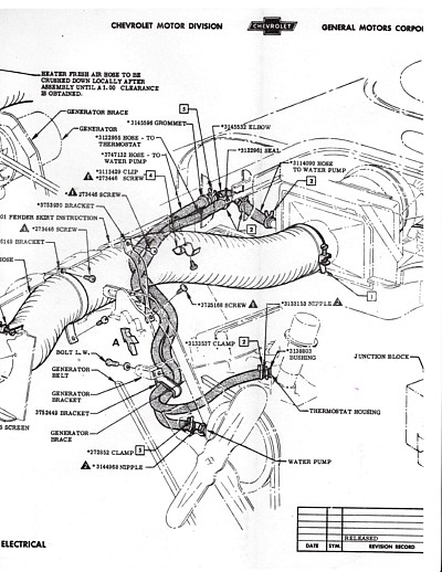
From:
Verle Randolph, Red River Chapter VP:
The heater hoses do not connect directly to this over flow system. One
heater hose connects to the water pump, small connection just above the
radiator hose connection. The other heater hose connects to the right front
of the intake manifold, not the hole on top of the intake but on the front
of the intake..Note the hose connection sticking out upper left in the
picture.
Verle
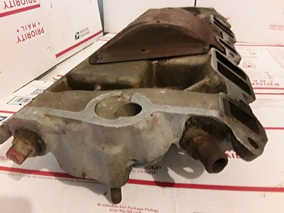
From:
Larry Pearson, SoCal Chapter Advisor:
Rex: The routing of the two heater hoses plus the two brackets that hold
them and the aluminum tie strap are all pictured in Figure 24 (Heater
Connections) on page 1-13 of the official GM shop manual for the C-1
Corvettes: Corvette Servicing Guide, publication ST-12. If you don't have
this manual, it it a "must have" for C-1 Corvette owners, and is available
in reprint from all the major Corvette parts suppliers.
All the fittings and brackets are available from Corvette Central if you
need them. The part numbers are:
451345 Heater hose bracket on inner fender (W shaped) This screws to the
inner fender fiberglass above the battery.
451316 Heater hose bracket on generator support bracket bolt.
451330 Aluminum tie strap (the long one). The short one ties the two small
hoses going to the aluminum expansion tank.
451326 curved fitting going to the right hand side of the water pump.
451327 straight fitting going to the intake manifold.
The heater hoses were originally held on to the fittings with simple
"Corbin" spring clamps. These are self tightening and work fine with your
13 lb system. If you are going to a higher pressure system you probably
should use a screw type or a tower or worm gear type clamp. These type
clamps are not self tightening and you should re-tighten them shortly after
driving the car. The rubber hoses compress slightly after they thermally
cycle a few times.
Larry Pearson
**********
12/05/2020
I have a 1961 fuelie. Should this car have the generator with the tach drive
or a standard generator
Thomas
From: Bill Huffman,
Michigan Chapter Advisor:
Tach drive
on your 1961 fuelie depends on its HP rating.
A 275 HP w/
7077200 FI and a1010915 distributor with one output that only drives the FI
fuel pump needs a tach drive generator.
A 315 HP FI
has a dual drive distributor that drives both the tachometer and the FI fuel
pump.
If your car
has a lower RPM redline it should be the 275.
Bill
Huffman, Pres.
Michigan
Chapter SACC
From: Larry Pearson, SoCal
Chapter Advisor:
Your car should have a high performance 35 amp generator with cast steel ends
and dual ball bearings (front and rear). The part number should be 1102268.
According to the Delco Remy application catalog, this generator was also used
on pickup trucks, so it should be common, But it is not, and it gets very
expensive to buy one. Your FI distributor should have a tach. drive fitting
on it for your tachometer.
If you are not having your car judged, any 30 amp generator will work. If you
have a 4:11 or 4:56 rear end or are using low profile tires you should have a
dual ball bearing type generator because of the high engine speeds it will
encounter. It should also have a large diameter pulley to reduce generator
speed.
Larry Pearson
**********
I have just removed the body off my 1960 corvette. I have been razor blade
stripping the last coat of paint (2nd coat painted over orig in
1970). What is the best way to strip the original paint and primer, I have read
about many options.
From: John Spencer, Red River Chapter Advisor:
Some enthusiasts don't recommend this method
because unless the surfaces are washed very thoroughly you acn leave behind a
chemical residue that will ruin a new paint job. But with care this can be
prevented. I have attached some photos of the process I have used numerous
times. The color coats (repaints) strip easily but I find teh original factory
coats to be a little more stubborn. I use a chemical stripper (bought from your
paint supplier - not home depot). Put on a good pair of rubber gloves and have
a bucket of clear water by your side at all times. Use a paint brush to apply a
liberal coat of stripper - wait - let it do its job. The paint will bubble up
(you may need a second coat/application of stripper) Use a plastic bondo
spreader (not a metal putty knife or razor blade) to scrape off the stripped
paint. This will almost be a liquid. Scrape the paint off the spreader into a
coffee can or other suitable (throw-away) container. You may need to repeat
this step several times. When you get down to the last coat (primer) scrub the
stripper with steel wool to get to bare glass. Apply one more coat of stripper
and scrub it with a clean steel wool pad - only this time, apply running water
to the area while you scrub instead of scraping the stripper. The last step is
the critical one. Apply plenty of water (from a running hose) while you
scrub/clean the stripper off. This removes the chemical residue that will ruin
your following paint job. The result is a clean glass surface that is not
gouged up or damaged. After the glass dries, a light sand job will prep it for
the repainting process. See photos attached. Good luck !!
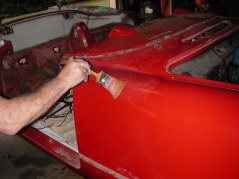
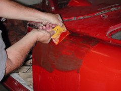
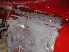
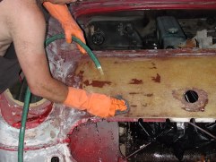
From: Chip Werstein,
SoCal Chapter Advisor:
Stephen,
I have stripped numerous C-1 Corvettes over the years. I have used a PPG
stripper designed for use on fiberglass which will not attack the the
fiberglass. It will take off the original lacquer and some factory primer. The
remaining primer needs to be wet sanded off using 220 grit paper. It is a long
and tedious job. Others my suggest faster and easier methods using stronger
stripper etc. but you run the risk of damageing your gelcoat and glass matt.
It has been several years since I've tackled a job like that and there may be
new/better products available
today.
I would check with PPG and other major paint manufacturers for advise.
Chip Werstein
**********
11/12/2020
Hello,
I
have a 1954 Vette with a problem that I hope you can help me with.
I've searched for a solution, but with no success.
The
ignition switch has four positions (LOCK, OFF, ON, START). The finger
guard of the lock cylinder has one hole on the right side for insertion of the
cylinder lock removal tool (AKA paper clip). My lock has become
difficult to get in and out of the LOCK position, so I no longer use the LOCK
position. I’d like to replace the lock cylinder.
I
have seen videos of ignition lock cylinder removal on newer Chevys, but not on
the '54. Newer locks have two holes on the left side of the finger
guard; mine has only one hole on the right. Also, newer locks have an
ACCESSORY position all the way to the left; mine has no ACCESSORY position.
For newer locks the instructions say to put the lock in the ACCESSORY
position, insert the paper clip into the bottom hole, and pull out the
cylinder. Without more explicit instructions that apply to a ’54 I’m
reluctant to move ahead because I don’t want to screw something up. So
here are my questions if you can help.
How
do I remove the lock cylinder on my '54? Do I insert the paper clip when
in the OFF position or LOCK position? Or I just leave things alone and
learn to live with the problem and not use the LOCK position?
Do
you have a recommendation for a replacement lock cylinder? I see that
the Standard Motor Products US21L may work. Another
option is the Dorman 989-037, but the finger guard may be too
large. Also, I've seen references to GM 3772085. I
don't know if that's the OEM part number, and I wouldn't know where to find
it. Any suggestions?
So
that’s the story. I don't want to get the existing cylinder stuck in
the LOCK position, which would render my Corvette undriveable. If you
can provide any guidance, it will be greatly appreciated.
Many thanks.
John
From:
Chip Werstein, SoCal Chapter Advisor:
John
Contact Pete Lindahl 505.412.2389. He is the lock guy. He my even have nos ign
switches. Nice guy, quality work. I have used him for years.
Chip Werstein
**********
11/10/2020
I have a 1962 with a 327 / 340 hp , my garage floor under my tail pipes is
full of black soot every time I start her up and it will clear it self after a
few minutes.
Can you help?
From:
Verle Randolph, Red River Chapter VP:
Black smoke suggest an over rich fuel mixture.
A cold start will have the choke set so the mixture is richer. After a short
time the choke will open reducing the mixture so the black smoke ends.
The choke may be set too rich.
Verle
**********
11/6/2020
As far as I know and can tell, my 1958 never had any windshield washers.
Since I am going to be installing a new one piece front end from the upper
dash forward on my 1956, I am wondering whether windshield washers were an
option. I am thinking of leaving it washers delete as my 1958 appears to
be.
Thank you,
Michael
From:
Larry Pearson, SoCal Chapter Advisor:
Michael: According to the NCRS Specifications Guide, the windshield
washer on the 1956 was standard equipment until "approximately April of
1956", after which it became FOA 109, a $11.85 option. If you are
planning to have NCRS judge your car and your car is an early one, you might
need this. If you have it, why not install it?
Windshield washers were an extra cost option until 1962, when they became
standard on the car.
Larry Pearson
From:
Joe LeMay, SoCal Chapter Advisor:
Hi Michael
In 1956, windshield washers were a required option through March
1956. All cars were fully optioned with 2X4 barrel, windshield
washers, power top, parking brake alarm, and courtesy lights. If you
have an early car, those options were present. This was covered in a
bulletin on April
6, 1956.
BTW, there is no such thing as washer delete, radio delete, heater delete;
they were listed as options.
**********
11/2/2020
What is the correct procedure for installing the harmonic balancer? I
would assume that you get it started and then drive it on by placing a piece
of hardwood or a brass cylinder on the center of it and hitting it with a
hammer. I looked in the 1957 Motor's Auto Manual, but it didn't have any
description of how to install one. I just want to make sure that I do it
correctly.
Thank you,
Michael
From:
Joe LeMay, SoCal Chapter Advisor:
If you are removing the motor, have the crank tapped for a retaining bolt.
I believe it was a 7/16-20 X 2 1/2. It is a safety issue if you have
heard from someone who had their balancer fall off. I know there were no
balancer bolts in 56-57, but we learn.
If there is a bolt, install the balancer with a threaded rod. Screw
the rod all the way in, then use a washer and nut to pull the balancer on.
Otherwise the threads can strip on a bolt if the fit is tight. Then
remove the rod and replace with a bolt.
If you do not have a threaded hole, use a rubber mallet to drive the
balancer on.
From:
Larry Pearson, SoCal Chapter Advisor:
Michael: If your crank snout is threaded, use a grade 8 bolt with a
thick washer(s) to pull the balancer onto the crankshaft.. Choose a bolt
long enough that it threads at least 1/2 inch into the crankshaft threads
before starting the installation Once the balancer is completely seated
on the crankshaft snout, use a bolt and washer as described in the next
paragraph to assure that the balancer stays in place.
If the crankshaft snout is not threaded, you have to pound it on with a heavy
steel hammer and a thick block of steel, brass or aluminum. Do not hammer
directly on the balancer. Wood and rubber hammers won't work.
If the balancer is used and goes on easily, it will come off easily, and that
is not acceptable. If you cannot get a balancer that goes on tightly,
then you will have to find a way to drill and tap the crankshaft snout.
The thread size should be 7/16x20 and the retaining bolt should be 2 1/4
inches long. This bolt length is too short to use to pull the balancer
on. The factory washer part number is (was) 3739422. Corvette
Central can supply the bolt and washer. Also, use a lock washer over the
flat washer.
One more thing. A special round washer type spacer with a notch to clear
the key should be on the crankshaft snout to space the balancer out by the
thickness of the front cross member engine mount to cause proper belt
alignment. This always ends up missing whenever an engine gets rebuilt.
Once the engine is together, there is no easy way to determine if this spacer
is in place. If you have access to a loose crankshaft, measure the
length of the snout and then use a caliper depth gauge to see if your snout is
slightly shorter, indicating that the spacer is in place. The original
GM part number for the spacer was 3734984. Corvette Central can
supply it.
Larry Pearson
**********
10/18/2020
Wondering if someone has an opinion on new black carpet for a 62
-Garry
From:
Bill. Huffman, Michigan Chapter Advisor:
Garry,
Most carpet from Corvette suppliers will be from Al Knoch Interior.
Their stock 1959-1962 black carpet is a black/olive tuxedo carpet intended to be
identical to GM original. I'm sure there may be vendors who sell a true black if
that's what you want.
It' your car, make yourself happy.
One thing I've learned in 5o + years of owning Corvettes, the next owner will
most likely want it in stock condition so they don't need to re-do it.
Hope every mile is a happy memory,
Bill Huffman, Pres.
Michigan Chapter SACC
**********
10/15/2020
Hello — I just bought a 1962 Corvette with the 327 / 340 hp engine,
numbers’ matching, a little rough, but it’s all there. However
someone sanded the paint down to the fiberglass. 1) What is the
best/safest primer to use for covering this bare surface? 2) How does one
safely remove oil spots from the bare fiberglass surface? 3)
What’s the correct color for the rear end housing, the 3rd member
‘pumpkin’, and the backing plates? 4) Can you recommend a written
source which provides detailed pictures, restoration info, component colors,
hose, line routing, etc.?
Thanks. -Rex
From:
Verle Randolph, Red River chapter VP:
The best source is the National Corvette Restoration Society.
Scroll down to the 61-62 manual. This is a 364 page manual with detailed
information.
If you want a correct/original restoration I suggest you join NCRS. There are
chapters across the country.
Many of us in SACC are also NCRS members.
Don't be afraid to ask questions here.
From:
Larry Pearson, SoCal Chapter Advisor:
Rex: On questions #1 & #2, you need to contact a Corvette body shop
in your area that has an excellent reputation for painting Corvettes.
The car was originally painted with Acrylic Lacquer and this material has been
banned by the EPA in most areas of the country. Major paint
manufacturers like Ditzler no longer make all the toners that are required to
make the correct colors. Also the primer originally used is no
longer available. The cars were not clear coated. Don't plan on
painting a Corvette yourself or having a general purpose body shop paint it.
Properly painting a Corvette can take six months and costs lots of money.
At least your car has already been stripped down to bare fiberglass, and this
saves you lots of money. Now it will be easy to determine if any
bodywork is required. On the assembly line, it took about four hours to
primer and paint the car, and the resulting finish had lots of orange peel and
was not even close to being show quality.
On questions #3, the entire chassis including the brake lines and backing
plates, brake drums, one side of the brake master cylinder and the line going
up to it, the front and rear suspensions including the springs and shock
absorbers and rear axle assembly, the rear axle rebound straps and even the
exhaust system (most of it) was painted with chassis blackout paint.
Prior to 1962, the cast iron transmissions were painted with chassis blackout
paint. The 1962 cast iron three speed transmission was probably painted
chassis black, but not the 4-speed and Powerglide transmissions, which were
aluminum. This final blackout painting was done just prior to the body
being mounted on the frame. This paint was an inexpensive petroleum
based material, that is referred to as "tar"paint and quickly
deteriorates. I recommend using black enamel, and originally the finish
was glossy when new. The rear axle rebound straps don't look painted because
the paint they used absorbed into the material. I have road test photos
and assembly line photos of new Corvettes that prove all of this.
On question #4, if you are going to have NCRS judge your car, you need to join
the organization and obtain their judging manual and do everything it tells
you to do. This manual is a "cook book" that judges use down
to the letter. In SACC, we do not judge Corvettes. We maintain and
enjoy them. Doing everything in the NCRS judging manual gets very
expensive. If you are not going the NCRS route, the Corvette Assembly
Information Manual (A.I.M.) should tell you everything you need to know about
how the car was assembled, The A.I.M. for the 1962 Corvette is available
as a reprint from most Corvette parts suppliers.
**********
10/06/2020
My 62 starts and idles great. When I take off it starts to miss on 1st
2nd and third, not as bad on fourth. I replaced plug wires, cap and
rotor, and rebuilt the carb but nothing is working.
-Adnan
From:
Larry Pearson, SoCal Chapter Advisor: Adnan: Make sure that your
timing is properly set. The timing mark on your harmonic balancer (damper)
may have shifted due to deterioration of the rubber in its construction.
To verify that the timing mark is correct, you will have to determine the actual
top dead center. You can do this by removing the #1 spark plug and
carefully turning to engine over with a screwdriver in the spark plug hole to
determine when the piston is at the top of travel. If your balancer is
retained by a bolt, you can slowly turn the engine over using a 1/2 inch
ratchet. If not, remove all of the spark plugs and turn the engine over
using the fan blades, if it is rigid (no fan clutch). If none of the
above, you will have to turn the engine with a screwdriver on the teeth of the
flywheel and with the use of a helper.
Once you have determined top dead center, mark it with a Sharpie on the edge of
the balancer is it is different from the factory mark. Then replace the
balancer as soon as you can, because it is defective.
If the timing is correct, try a new coil. Check the spark plug wires for
continuity with an ohm meter and insulation breakdown by looking for sparking in
the dark. If the wires are of the radio suppression type, the resistance
should be about 1000 ohms (I think). Ten thousand ohms or higher is too
much. Check the ballast resistor for continuity with an ohm meter.
It should be between 0.5 ohms and 1.5 ohms.
Larry Pearson
From:
John Spencer, Red River Chapter Advisor:
Adnan - Larry is correct to suspect timing, but I would suspect the distributor
advance more than a change in the harmonic balancer. You can check this
with a timing light. Hook up the timing light and watch the timing mark on
the timing chain cover and its relation to the mark on the balancer as you goose
(highly technical term meaning open rapidly) the throttle. You should see
the timing mark move in relation with the timing chain cover tab. If it
don't you have a vacuum advance problem (usually presented as a faltering of the
engine during acceleration) or a mechanical advance problem (more typical of
what you're describing). When you first crack your throttle you should see
the timing drop (vacuum advance function) then advance with RPMs (mechanical
advance function). Otherwise it sounds like you've addressed the other
suspects. Good luck - John
**********
09/29/2020
I have been restoring my ’59 for 30+ years. I’m on the downhill side of
this project. But, I’ve run into a problem of how to adjust the door hinges
& align the doors. Every source I’ve found only shows the locations of the
hinge bolts which control the alignment & some mentions possibly using
shims. However, I’ve found no info on what procedure or order to follow. My
efforts so far have been less that acceptable. Can you suggest where I can
find such info? Thanks for your time & any guidance or help you might offer.
Lewis
From:
Larry Pearson, SoCal Chapter Advisor: Lewis: The procedure is found
in the only official GM shop manual for C-1 Corvettes: Corvette Servicing
Guide, Publication ST-12. Reproductions of this manual are available from
all the major Corvette parts supply sources.
The explanation is found on page 1-19, DOOR HINGES and refers to figure 31 on
page 1-17. The door is held to the upper and lower door hinges by three
bolts per hinge. The bolt access holes were originally covered with round
black felt covers to keep rain water out of the area behind the door panel.
If you loosen (don't remove) these three upper and lower bolts, the door can be
shifted up and down and back and forth to a small degree. As you adjust
the doors as necessary for proper alignment with the body exterior, just tighten
one bolt of the three until you have the the door in proper alignment and then
tighten the other two bolts. If the door needs to move outward, you will
have to add round steel washers between the hinge and the door. If the
door needs to move inward, you will have to remove any shims that are already in
place. If there are no shims in place, you might have to take your car to
an experienced Corvette body shop for help on this.
There are two large Phillips head screws that hold the hinges to the body.
There is no adjustment here, so leave them alone. Be sure to lubricate the
flat friction springs in the body part of the hinge assemblies. Use
Lubriplate light white grease. There is an upper and lower flat spring in
each door hinge. These are to keep the door fully open with their friction
so the door doesn't close on you when you want it to stay open.
After you have the door properly adjusted, be sure to replace the round seals
using an adhesive. If there were no seals, use a couple layers of masking
tape over each of the six holes.
Larry Pearson
From:
Bill Huffman, Michigan Chapter President:
Lewis,
I had the
same problem with two different full restorations, this is how I did it.
Work
carefully, this is not the time to scratch the paint.
Attach
the hinges to the body "close but very loose" then mount the
door on the open position hinges.
Attach
the hinge bolts to the door "close but very adjustable".
Measuring
from the floor, lift & support the door level as close to final position
as possible then tighten the body screws to finger tight adjustable.
Cut 8 or
10 cardboard shims measuring 4" x 8". Tape them equally spaced
around the door opening, lengthwise across the sill to protect the paint.
Close
& latch the door. The fit / door gap should be uniform all around.
If it is,
Tighten the all door attachment bolts securely. If it's not, adjust the
latch on the body & try again.
Open the
door carefully without applying any extra load and tighten the hinge
to body screws.
You
should be done,
Bill
Huffman, Pres.
Michigan
Chapter SACC
**********
09/26/2020
I just bought a 1959 corvette that has Fuel Injection emblems on it and I am
trying to locate the build information to determine if it was actually built as
a fuel injected car. The original engine is long gone and just getting
started with the job of replacing tired parts.
From:
Bill Huffman, Michigan Chapter President:
Jeff,
The bad news is that there is no data base that contains the information you're
looking for regarding 1953-1962 Corvettes.
The paint & engine code plate under the hood wasn't added till 1963
production start.
The good news is that with publications such as the Corvette Black Book, the
NCRS 1953-1967 Corvette Specifications Guide and the GM 1959 Assembly
Instruction Manual, by comparing your car against the standard configuration of
the 4 optional engines, three transmission options, plus the numerous RPO's, the
car will tell you what it was.
Just remember, owner modifications over the last 61 years may give you
conflicting testimony. You are it's archivist, historian & conservator. Take
pictures.
If your car is a fuel injection car with the engine changed, all the various
components or their previousmounting located under the hood will be where the
AIM required them to be.
Good luck in your investigation
Bill Huffman, Pres.
Michigan Chapter
**********
09/23/2020
Hi
I have a 1958 Corvette 283 w/4 bbl. & 3 speed.
It has been taking a break in my barn since 1970ish
I just started cleaning up parts that I took off in 1976 and seeing what I
have.
I have a few questions.
Did GM / Chevrolet put 1957 intakes on the 1958 cars on the assembly line ?
I also have the 7 fin valve covers which from what I understand is put on
"optioned" engines.
Also on passenger side fender there is a red/white/blue emblem bar where the
fuel injection emblem would go on a fuelie.
Attached is a picture of each.
Mine is definitely a 1958 with all the fixings ( hood louvers, trunk Spears,
etc ) correct vin for that year.
Any input on this would be helpful ?
Thank you
Barry
From:
Bill Huffman, Michigan Chapter President:
Barry,
In the 25
years before this rough cut gem started it's break in your barn, ANYTHING is
possible.
If you
really want the real story, you are going to have to let the car itself tell
its own story, part by part, assembly by assembly, using date codes, casting
numbers and GM part numbers. You will need a 1958 GM Assembly Manual to
determine location of windshield washer reservoir & vacuum cannister,
washer tubing, tachometer drive, tach RPM Redline, engine block and a host
of other components to determine whether or not it could possibly be the
rare FI car you are hoping for.
I would
guess that this car was run hard, abused badly & put away wet long
before you two met. It likely needs EVERYTHING, and there is no cheap easy
solution here.
Sorry to
be a wet blanket but somebody had to say it. Might as well be me.
I
resurrected a 1960 ex drag race car from a barn 20 years ago.
I still
have it. I still love it.
Best of
luck with your dream car.
Bill
Huffman, Pres.
Michigan
Chapter SACC
From:
John Spencer, Red River Chapter Advisor: To my knowledge no 57 intake
was used on a 58, even early production models. The intake shown is a
57. The correct casting for a 58 is 3746829. The valve covers
are 7 fin covers used on 58s, but not the 230HP. The emblem shown is
interesting - it looks like the FI plate used on the 65 model but that
emblem had a "fuel injection" script on it. What is your
engine and head casting numbers and car serial number? It appears you
have a car that has been kept alive using parts from several cars - if you
are pursuing an NCRS numbers matching car - get out your checkbook. If
however you just want to restore your car to a period correct car (correct
CI engine, paint color, interior, etc) it opens up a wide variety less
expensive options. I have a 58 that I am very proud of, I restored it
in 1980. It does not have a Duntov award, but it has been viewed and
blessed by Mr. Dontov personally (in 1984). The SACC Tech panel is the
best source for info I know. If I can be of any help, don't hesitate
to call. - John
From:
Verle Randolph, Red River Chapter VP:
The date code on the intake appears to be "G" so that
would be July of 57. It is possible that it could have been installed on
an early 58.
I am pretty sure the emblem is not something that would be installed on an
early Corvette, it looks similar to the 65 Corvette FI emblem.
Is your 58 an early car?
Verle
From:
Chip Werstein, SoCal Chapter Advisor:
Barry
Your intake is a 57. Note the casting date is c 12 57.....march
12 1957. 58 cast number is 3746829.
Your valve covers are 1959. Off set holes with high script
corvette. 58 is the same but with low script.
F I emblem bar appears to be from a 65 corvette.
Chip Werstein
**********
09/21/2020
I installed a Jim Meyer Racing IFS on my 60 and now they
are out of business and I need Upper and lower control arm bushings. I was
hoping someone in your club might have some info on these.
Signed, Desperate in WI
From:
Bill Huffman, Michigan Chapter President:
Ned,
Corvette
Central in Sawyer, MI has been selling this C-1 suspension upgrade for several
years. I'd give them a call at 800-345-4122 and see if they can help you with
this.
Good luck,
Bill
Huffman, Pres.
Michigan
Chapter SACC.
**********
09/20/2020
I own a 1959 that has speedometer and
tachometer cables that do not rotate smoothly. I lubed both cables by
rubbing dry graphite along their length, less the last inch or more. It
helped the speedometer until I sped to 55-60 mph, the speedo needle really
bounced and before I pulled to the side, the needle dropped and stopped
working. The tach needle also bounces periodically. I have
disconnected both and now have a project ahead of me to remove them and send
them for repair.
Searching speedometer on this Technical Help
page really helped. A nice company in Colorado made a 18” test cable I
used to spin the speedo. Under finger twisting speed, I heard the same
bearing squeal emitted when the speedometer needle dropped.
Now to the question: Under an age old
topic, does one dry lube or grease lube speedo/tachometer cables? The
gentleman who made my test cable said that graphite will inevitably work its
way to the end of the cable and get in the speedometer. I just did what
my father taught me and used graphite powder.
Eric
From:
Joe LeMay, SoCal Chapter Advisor:
Hi Eric
I had the same issue. Tried repeatedly to lube and clean the cable.
There was no change.
A local speedometer shop inspected it and replaced the bearings and all was
good. There were no issues with the cable. Hopefully, the speedo
did not break the last time it was connected.
Joe
From:
Larry Pearson, SoCal Chapter Advisor: Eric: Sorry that this response
is late. I have 12 cars and have had speedometer problems like you describe many
times. I normally am able to fix the problem myself. I will tell you
how I do it.
The speedometer and tachometer cables must be lubricated with a light weight
grease. Graphite is not a proper lubricant for speedometer cables.
Years ago, the AC division of General Motors sold ST-640 Speedometer Cable
Lubricant. It comes in a metal toothpaste type tube and is white and is
very soft. I recently asked a speedometer repair show what to use, and
they said to use a light weight general purpose grease. Use Lubriplate
grease if you can find it.
To lubricate it, pull the cable from the casing and inspect it for damage.
Then use your fingers to apply the grease to the cable as you push it back into
the casing.
Now for your other problem. The squealing is caused by the speedometer or
tachometer bearings being dry. In my experience, you can lubricate these
bearings yourself. Check the bearings for excess wear by turning the shaft
end with your fingers and check for up and down movement, indicating excess wear
that will require a rebuild. If there is no evidence of excess wear, drill
a small hole, around 1/16", in the top of the casing just at the end of the
threads where the cable nut threads on. There are two bronze bushings that
support the speedometer shaft, and this will put you at about the middle between
them. Inject a small amount of oil into this hole. I use a
hypodermic needle. Use 50 weight engine oil or 90 weight gear oil.
Originally, these bushings were greased, but it is hard to get grease into this
hole and to where the bushings are using this method. Rock the speedometer
back and forth to get the oil to the bearings. Spin the shaft with your fingers
to make sure it is free. When in operation, the cable spins at 1000 rpm at
60 mph, so good lubrication is a must. The tachometer cable spins at half
engine speed, because the distributor/generator adapter operates at half engine
speed. If you have a shop rebuild the tachometer, make sure that they
calibrate it to read twice shaft speed.
Whenever you hear the speedometer or tachometer make a squealing sound,
immediately pull over and disconnect the cable . This vibration can
greatly damage the inner workings of the speedometer in very short order.
It sounds like your speedometer has suffered internal damage and lubrication
will not help it. With the speedometer or tachometer, if you spin the
shaft in the correct direction with your fingers and the pointer does not move,
you will have to have the unit rebuilt. You can make a test adapter out of
a nail. Pound the end square with an hammer and use an electric drill to
spin the shaft at varying speeds to make sure that the pointer moves smoothly.
If not, you will have to have it rebuilt to fix this.
Corvette Central offers a rebuilding service. Mechanical speedometers and
tachometers with a cable have not been manufactured for many years.
Everything is electronic today,
and it is hard to find someone locally who has the parts and knowledge to
properly rebuild and calibrate your units.
Larry Pearson
**********
09/19/2020
Do you have any hints on replacing rear shocks on a 1962? I have a customer
with a very nice black/red 250HP/PG. The problem is very little access
to the top bolts. Fortunately, the left shock broke off at the top and removal
won’t be a problem. My thought for the right one is to remove the muffler
for access and use a zizz wheel to cut through the shock at the bottom rubber.
Tightening will also be a problem. There isn’t room for turning the nut with
a wrench. You could hold the nut from turning and turn the shock but it would
be hard to get it tight. Is it possible to get access to the top nut with a
hole through the body? What am I missing?
Thank you.
BTW, by father had a new Corvette in ’57 and traded it for a new one in
’59. I had a ’66 coupe I bought for $2100 in 1972 and put a 370HP 350 in
it. Had to sell it for $12K in 1984 when I started a family.
From:
Joe LeMay, SoCal Chapter Advisor:
Hi Spencer
You need a copy of the AIM Section J Sheet 3. Look at View A on that
page.
In the folding top compartment behind the gas tank cover, there is an access
hole that allows a socket or wrench to be put on top of the shock.
Joe
Update: The access hole is correct for a 1957. Later C1s at
some point eliminated the access hole. One can still assemble the shock
from below by twisting it to tighten the bolt.
**********
I am hoping that you would have help/instructions for removing the horn
button on a 1962 Corvette.
-Charlie
From:
Bill Huffman, Michigan Chapter President:
Charlie,
The horn button is retained inside a split spring steel stamping that also acts
as the horn contact by three equally spaced retainer detents under the button
face.
Insert a flat tool that won't scratch the steering wheel on both sides of
the button and pry up. It should pop off.
Good luck,
Bill Huffman, Pres.
Michigan Chapter SACC
**********
09/08/2020
I just recently purchased a 3 speed transmission mount bracket from Corvette
Central. When I went to install it I discovered that the bolt holes in
the bracket were about 2 or possibly 2 1/8 inches on center, and my
transmission mount holes are 3 1/4 inches on center. I believe that is
the measurements of a 4 speed transmission mount bracket. My
transmission main case has a casting number of 3845122 and is dated G 9 56.
The side cover is 3731911. but the tail shaft housing is cast 3855710 and is
dated D 28 5. I assume that I have the wrong tail shaft housing, but
what do I have? Is it from a 1955 Corvette? Would I be able to use
a 4 speed transmission mount bracket, or should I try to find a 1956 tail
shaft housing?
Thanks,
Michael
From:
Joe LeMay, SoCal Chapter Advisor:
Hi Michael
You have a few different items. The main case is a 56, but cast in
Tonawanda and was never used in a Corvette. The 3855710 tail was used
on 1965 Corvettes.
I do not know about that tail mounting arrangement. The correct 3
speed will mount to the C1 tailhousing. I am using a early 3 speed
shifter with a later C1 tailhousing. You should be able to acquire a
later C1 tailhousing. The 1956 3722946 tail may be pricey.
The
3 speed shifters mount to the transmission tail without a bracket. The
shifter is arranged with holes to match the tailhousing. Check the AIM
and you will see that.
The
bracket at the bottom of the transmission is different for a Muncie 318 3
speed and a BW T-10. The height is greater for a BW but the spacing is
the same. That bracket you purchased may be the plate that allows
using a Muncie M-20 with a C1 transmission crossmember. You would need
to describe if it is a flat plate with four holes in it.
**********
09/05/2020
Hello guys,
I have had a 58 Corvette for many years. When I bought the car it had an
aftermarket scissor jack and never really did anything with it. I have
recently found an original Jack correct for my car. The bad news is the jack
(the block thaty the screw goes into) is stripped. The screw is fine and I
think has Acme threads? Any idea how to repair or who might be able to help?
Thanks!
From:
John Spencer, Red River Chapter Advisor: Fred - I too have a 58 (great
choice) and an original scissor jack. Although my jack is in mint
condition - I would never use it. A scissor jack is a very dangerous tool.
If you need to raise your 58 for any service, use a hydraulic floor jack.
Use the scissor jack for show only.
From:
Larry Pearson, SoCal Chapter Advisor: Fred: I own a 60 Corvette that
I purchased from the original owner. It had the original jack and it had
probably been used only once and it had completely fallen apart. The
original jacks that came with these cars are dangerous to use and are
recommended for show judging only. Even the reproductions of this jack are
not recommended to jack up the car, only for NCRS judging. My 62 came with
a far superior jack of a different and better construction. The
aftermarket jack that your car came with is undoubtedly a much better and safer
jack to use for everyday driving. I question that the jack you have
is a correct original one because for the threads to strip, it would have been
used many times, and that is not possible with the original jacks.
If you are having your car NCRS judged, and if, indeed, your jack and jack
handle are correct looking and will pass a visual check, leave it the way it is.
NCRS judging does not check the jack operation, only the look. You
shouldn't be able to see that the internal threads are stripped by looking at
the jack.
Larry Pearson
From:
Bill Huffman, Michigan Chapter President:
Fred,
Over the years of owning a C-1, I have learned that a good aftermarket scissor
jack is:
1) visually undisguisable from an original if you remove limiter
tubes over the Acme screw,
2) they are unsafe to use for anything more than car show browny
points
3) most guys carry an small aluminum floor jack for emergencies.
The Acme nut in your aftermarket would most likely fit the original screw but
tearing down both jacks to swap parts means reassembling the original and which
will still be unsafe to use.
My advise, use the modified aftermarket jack or put the original jack in the
spare tire well under the 6.70-15 bias ply spare for show or points. I've never
seen an owner asked to actually jack-up the car with it.
Keep a real floor jack for emergencies.
Bill Huffman, Pres.
Michigan Chapter SACC
**********
09/02/2020
Does anyone sell the drain plugs below the fuel tank on a 1959 corvette
Thanks
From: John
Spencer, Red River Chapter Advisor: The only openings I know
of under the tank are for ventilation - no plugs
**********
08/29/2020
Hello,
I am building a 327 340hp engine for my
’62 Corvette. It has a NOM 283 dressed to look like a 300hp 327 engine
currently and it originally a 300hp car.
I figured it would be nice to have a correct,
though not #s matching 327 340hp style engine in my car. Things are
progressing pretty well except for the issue with the oil pan. I sourced a
6qt trap door SHP oil pan w/windage tray; though now my engine builder is
stating it won’t clear the ’62 suspension/steering. Apparently, this
pan is actually from a 1963 engine and while it will be fine on the engine
itself, it won’t work in the car.
Are the ’62 and earlier SHP pans specific enough that a
’63 and up SHP pan will not fit (IE interfere with the car)? Do I need
to try and find a ’62 and earlier pan? It took me a long time just to
find this one. Thanks for any help on this!
Greg
From:
Chip Werstein, SoCal Chapter Advisor: Greg
62 corvette pans are 5 guart. Engines hold 6 quarts....5 in pan, 1 in filter.
All 62 pans are the same 2 step configuration but the 340 and 360 pans have the
trap door. They were also used in eariler cars. Dont think 63 pan will work. 62
style pans are out there but getting difficult to find. You could use the 250,
300 hp pan as it looks the same from the outside. Most likely Dave Sokolowski in
Calif. Has a few of both styles. He advertises in the ncrs driveline.
Chip Werstein
From: John Spencer, Red River Chapter Advisor:
My GM Parts manual shows the 57-62 oil pan to be a five quart pan #3789629.
These pans are commonly referred to as three step pans (the third step
is required to clear the steering) For a visual see the following
link
ebay.com/i/362969807298?chn=ps&mkevt=1&mkcid=28
**********
08/25/2020
I have 61 Corvette with Dual
Point Distributor and Dual Quads I replaced the Dual Point with Pertronix
91183 Ignitor 11 in place of the Dual Points.
The car start right up. Idle great, but under a load it misfired and shut off
while driving it. Called Pertonix they total me that the mechanical advance is
Not working. Could this be possible. Has anyone install Pertronix in place of
dual points?
Thanks,
Glenn
From:
Chip Werstein, SoCal Chapter Advisor:
Glen
You must use a pertronix coil with their ignition system. Also, the pertronix
requires 12 volts to trigger it so if you are using a ballast resister connect
the trigger wire to the 12 volt side.
Chip Werstein
From:
Verle Randolph, Red River Chapter VP:
From Pertronix installation instructions:
1. IMPORTANT: Read all instructions before starting
installation.
2. DO NOT USE WITH SOLID CORE SPARK PLUG WIRES.
3. The Ignitor II ignition can be used
in conjunction with most ignition coils rated at 0.45 ohms or greater.
4. All external resistors must be removed to achieve optimum
performance from the Ignitor II ignition system.
5. The Ignitor II is compatible as a trigger for most
electronic boxes.
**********
08/24/2020
I have a 54 and when I open hood and pull up
I need assistance from another person to pull towards cockpit
It seems in a bind
From:
John Spencer, Red River Chapter Advisor:
The hood hinge leaves a lot to be desired. It seems to bind just as you
lift the hood. Depending how worn the
hinges are. I know of no adjustment to fix this problem short of the
hood stops that fix where the hood rests.
From: Verle Randolph, Red River
Chapter VP: It may need the hood hinges adjusted.
Lubrication on the hinges helps.
Verle
From:
Joe LeMay, SoCal Chapter Advisor: The hood support can stick.
**********
08/19/2020
I have a 1960 that has been sitting for 42 years. I just started
cleaning and pulling numbers from under the hood items. I know the VIN
plate is suppose to be spot welded to the steering column, stamped and made from
stainless steal. While cleaning the dirt off the VIN plate I noticed it
was loose, I pried it up and discovered it was glued on. I took a magnet
to it and it does stick. Does a magnet stick to the VIN tags for this year
vet as true stainless does not.
Thanks
Steve
From:
Larry Pearson, SoCal Chapter Advisor: Steve: I own a 1960 and
checked the VIN tag last
night with a magnet, and it is very much magnetic. The question is
why was your tag glued on? The car could be stolen, of course. Or it
could have been in a severe accident that required that the steering column be
replaced and the tag re-attached to the replacement column. If the engine
is the original one, the VIN number is stamped on the front pad of the block
along with with the manufacturing date code and horsepower/transmission code.
The VIN number is also stamped in large characters on the top of the frame under
the driver's seat. Reading this requires that the body be somehow lifted
above the frame in this area about one inch so you can read it. If the
frame is badly rusted, this number might not be readable at all.
If you are planning to have this car judged by NCRS, they very thoroughly
evaluate this tag and its attachment. They don't pry on it to verify that
it is spot welded on, and you can epoxy it on in such a way that it looks
correct. Also, they make portable spot welders and it might be possible to
have this tag properly spot welded in place. There is an industry that
reproduces this tag and apparently it is not exact and can be detected as a
replacement. NCRS will not judge the car if this tag is suspect. You
will be required to have your DMV verify the car's VIN, and this gets very
messy. If you plan to have NCRS judge your car with this re-attached tag,
do not discuss anything about this issue with the judges. Let them figure
it out.
Larry Pearson
**********
08/15/2020
Will a 3rd member out of a 1962 nova fit in a 1959 corvette?
From:
Verle Randolph, Red River Chapter VP: I have never tried
it but I believe it is the same as Corvettes and tri five Chevies. Probably a
tall gear.
Verle
From:
Larry Pearson, SoCal Chapter Advisor: Wishbone: The 1955 through
1964 Chevrolet full size sedans use a differential assembly that will fit your
1959 Corvette. The 1962 Novas were much smaller than the full size sedans
and had a four and six cylinder engine option. In my opinion, it is highly
unlikely that the differential supplied with this car was the same size as that
used in the full sized sedans. The full size sedans came equipped with
everything from a larger six cylinder engine to a 409 W motor.
Larry Pearson
**********
08/14/2020
I started the job of installing new king pins in my older restoration,
1962. This is a project that I have put off for a while mostly because
of being too busy until now and the fear of messing up a restored car.
After just completing the front end rebuild on my 1956, i discovered that king
pins aren't such a hard job to replace. Within less than an hour I was
nearly ready to remove the first king pin in the '62 and then the project came
to a halt. I couldn't get the lock ping to move and be allowed to be
driven out. I tried hitting it by first placing a piece of hard wood
against it and hitting that with a good sized hammer and then with a brass
shaft and the hammer. It still won't move. I sprayed rust buster
on it and also sprayed some down from the top of the king pin and decided to
wait until morning an hope that it frees up. I'm guessing that I am not
the first one to encounter this problem. Is there any tricks that I
haven't thought of to free my lock pin?
Thank you,
From: Joe LeMay, SoCal
Chapter Advisor:
The lock pin you are refering to is the pin driven through the spindle support
and secured with a ~5/16 nut?
You may have to hit the king pin up and down to try to loosen the lock pin.
I may have been overtightened when it was installed and is now stuck.
From:
Verle Randolph, Red River Chapter Advisor: I agree, you
may have to drive the king pin up and/or down a little.
If penetrating fluids and such like don't work, try a strong solvent in case
someone used locktite. Not likely but who knows. I like B-12 carburetor
cleaner for this.
Might also try a?? C clamp. Tighten C clamp on the pin making sure the back
side is open so the pin can move. Get C clamp as tight as you can, then strike
the C clamp with a hammer.?? Grasping at straws here.
Verle
From:
John Spencer, Red River Chapter Advisor: Sounds like you have a problem.
Were you able to remove the nut holding the pin in ? If so you
might try running a nut back on the pin (run it on several threads short of
seating). Use the nut as your impact surface - not the pin itself.
This way you won't risk mushrooming the pin. If penetrating oil
and a brass rod don't free it - the only other suggestion is heating the
steering knuckle to expand it. To do this you have to completely
disassemble the knuckle.
Thank you all for your help. I am able to easily remove the nut and
the lock washer and I have put the nut back on and have been hammering on it
by using a one inch piece of brass that is about six inches long. i
have used a C clamp and hammered on that as suggested. I was thinking
of heating around it and I have a question for Mr. Spencer. Why would
I have to remove remove the knuckle before I heat it? Is it because it
would have to get so hot that it would burn the grease seals on the control
arm shafts?
Thank you,
Michael
Access and mass. I know its a pain to remove the knuckle from the
brake assembly and A-frames, but it allows you to work on the knuckle on
your workbench - not the car. This gives you very good access and it
removes the part from the car (I'm very nervous with a torch around my
fiberglass cars). Additionally - it removes any additional mass which
draws heat. All you want to heat is the
knuckle
around the lock pin.
**********
08/06/2020
Before I install my harmonic balancer I wanter to check to make sure that I
have the correct one. My balancer has a casting number of 37680 on the
inside of the center section and although it has been painted black, I would
assume that the balancer on a 265 cubic inch engine should be painted the red
engine color. So do I have the correct balancer and am I correct in
thinking that it should be painted red? It is a stock 1956, 265 cubic inch.
Thank you for your help.
>
> Michael
From: Verle Randolph, Red River
Chapter VP: I looked up that casting number and it does
not look like what I think a 56 265 balancer should look like.
Here is a very ugly one:
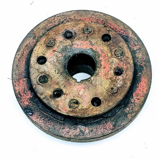
From: Joe LeMay, SoCal
Chapter Advisor: The photo below is similar to the typical factory
balancer but there are some differences. The typical one has a 3/8"
pulley riveted to the balancer and two threaded holes to remove the balancer
from the motor. See the attachment. There is no separate part number
stamped on the riveted pulley. This pulley is also used on 1957 corvettes
except the 270 and 283 HP motors. 270 uses a riveted 1/2" pulley with
the same balancer configuration (rare to find). 283 HP uses a 1/2"
pulley bolted to the balancer in three places. It would look like the
photo below. All balancers with riveted pulleys are painted engine color.
Balancer with bolted pulley is engine color. The bolted pulley is black.
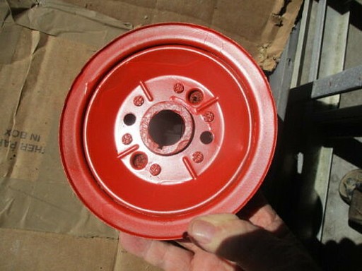
Thank you for the information that you supplied regarding the 1956 harmonic
balancer. I am sorry that I didn't include the horsepower of my engine,
but it sounds like in 1956 all horsepower engines used the same balancer with
a 3/8 inch pulley that was riveted on. Is that correct? Now I know
that the one I have is incorrect and possibly aftermarket. Do you have
any suggestions where I could purchase the correct one, and if I find one
without the pulley, could I get a new pulley riveted back on?
It has been many years since I have worked on this 1956 project and when I
would order new parts or buy used ones back then, I would put them away until
the day came that I needed them. It seems that I had put away two new
clutch forks. One has a oblong hole at the end where the linkage
attaches and the other one is slotted and they are both bent differently.
The assembly manual shows the one with the oblong hole in its diagram, but
parts catalogs show the one with the slot in it as being the one for
1955-1962. Can you please help me out with this question? I would
send pictures if I knew that there was a way to do that.
Thank you,
Michael
From: Joe LeMay, SoCal
Chapter Advisor:
Damper Doctors and Damper Dudes are two who would have one and do rebuilds.
They had what I was looking for. You can try the internet or ebay but that
one may require rebuilding, or the pulley may be bent.
There are two different clutch forks and bellcrank to fork pushrods.
1956 clutch linkage rod had a spherical end and was secured with a spring
clip to the clutch fork. There would be
a dish in the fork to accomodate the rod. 1957 clutch linkage rod had
a flattened end and was secured with a clevis pin to the clutch fork.
The fork has a rectangular slot. The 1957 configuration is shown in
the Paragon catalog. The 1956 parts are rare. The typical
adjustment swivel that attaches to the bellcrank is also rare. It will
be long enough to accommodate a coil spring that is shown in the assembly
manual. The current repros are for 1958 and up and are shorter.
They do not use the spring.
**********
08/03/2020
1958 Corvette. Parking brake issues, parked with parking brake
off since 1977.
Handle, shaft will not rotate. The shaft will not pull outward.
Is frozen … The pin that sets towards the fire wall is loose.
-Wayne
From:
John Spencer, Red River Chapter Advisor: If the handle will not rotate,
then the shaft must be frozen in the conduit. Your only recourse is to
get penetrating oil in there to free it. The conduit is open on top -
you can use a can of penetrating oil to apply the oil directly to the shaft
instead of spraying it. Otherwise you need to remove the brake shaft
assembly and soak it in kerosene.
**********
07/30/2020
> I would like to purchase a 1956 trunk lid from someone
> Do you know anyone?
>
> Thanks
> Rob
From:
Bill Huffman, Michigan Chapter Advisor: Rob,
This should be real easy.
https://www.corvettecentral.com/c1-53-62/body-frame/fiberglass-rear/56-60-trunk-lid-press-moulded-141093?returnurl=%2fc1-53-62%2fbody-frame%2ffiberglass-rear%2f%3fcount%3d27'
Ecklers, Chicago Corvette, Mid-America, et al sell the same parts.
If you're looking for an original, Paragon has one. https://www.paragoncorvette.com/p-349779-trunk-lid.aspx
Otherwise, hit the internet and remember- Condition, Condition, Condition. The
better it is, the more it costs.
Good luck.
Bill
**********
I have a 1957 corvette I am reassembling and I am trying to figure out
correct routing of headlamp and parking lamp harness routing and location
of clip for lamp to harness connector if you have any photos or documents.
From:
John Spencer, SoCal Chapter Advisor: Here is the routing for a 58 -
don't have an illustration for a 57 but they are basically the same I
believe.
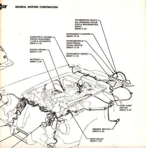
From:
Larry Pearson, SoCal Chapter Advisor: Bill: You need to purchase a
copy of the 1957 Corvette Assemble Instruction Manual (AIM), Reprints are
available from the major Corvette parts suppliers. These manuals were used
by the Corvette assembly plant to direct it on how to build the car.
You want Section 12, page 12. This page shows how the chassis wiring
harnesses were routed in the engine compartment of the car. Other pages
show how the rear of the car wiring was routed, and how the under dash wiring
was routed.
Larry Pearson
From:
Verle Randolph, Red River Chapter VP: The routing
shown for the 58 is the same for a 57. Headlight wiring clips are very
high, above the radiator on the grill side of the radiator support. Some
may be broken from bending too many times.
Verle
**********
07/28/2020
I am currently putting all the chrome etc. on my freshly painted 1960
corvette. I have new emblem kits for both the front and back. My
question is: where do you place the foam gasket; between the bezel and body or
between the body and the actual emblem or between the emblem and the backing
plate? Thanks in advance.
Rewards,
Book
From: John Spencer,
Red River Chapter Advisor:
Front Emblem assembly order (from outside surface);
Bezel-Body-Foam Gasket-Emblem-Backing Plate. See Illustration
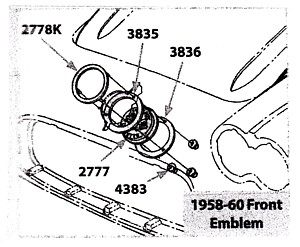
From:
Larry Pearson, SoCal Chapter Advisor: Book: The chrome bezel goes on
the outside surface. On the inside surface, the order is: Gasket,
emblem, and backing plate. There are special self threading winged nuts to
hold everything together. Pre-thread the special winged nuts on the three
studs on the bezel to make it easier to install them with the bezel in place.
Corvette Central sells a special tool to tighten these nuts, which you really
need. They do make a PAL self threading nut with a hex head which is a lot
easier to use, but it will not pass NCRS judging.
Larry Pearson
**********
07/23/2020
I have a customers 1962 C1 with a torn up clutch cross shaft bushing.I
have to question the direction the bushing is installed and wether it
has the correct shouldered bolt in place.He keeps tearing the rubber out
of the bushing.Any help,picture or otherwise is greatly appreciated.
Thanks in advance Don
From: John Spencer,
Red River Chapter Advisor: See illustration. Shoulder bolt is
Paragon Corvette P/N 628K ($10.00).
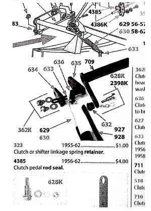
From:
Larry Pearson, SoCal Chapter Advisor: Don: The bushing assembly
consists of an outer sleeve that is pressed into the cross shaft with the
shoulder directed toward the engine, a rubber insulator, and an inner bushing.
In my experience with my two 62's, the rubber part rapidly disintegrates leaving
the inner bushing in direct contact with the outer metal sleeve. This is
particularly the case if you are using a high performance Borg & Beck
pressure plate which takes lots of pedal pressure to activate. I have
found that it works fine without the rubber part. It makes me wonder if
the original factory part used a more durable rubber compound than the service
replacement units.
If this bothers you, I strongly suggest that you purchase a replacement bushing
kit from Danchuck, the 55-57 Chevy parts supplier. Go online to see it.
Their catalog number is #345, and it currently costs $16.95. The heart of
their bushing kit is two identical bushings custom made of Delrin plastic.
These do not press into the cross shaft, they install with one on each side of
the cross shaft hole in place of the original pressed in outer sleeve.
Nothing is pressed in, so it is easy to service if it wears out. You must
remove the old outer sleeve to make room for this kit. I have been using
one of these kits for about 25 years in my "beater" 62 and have had no
problems with it at all. Of course it will not pass NCRS judging.
Larry Pearson
**********
07/22/2020
Hi!
Would like to know the exact measurements for placement of the front badge on my
1960.
Bought the car with 61 emblems.
VIN says it is a 1960.
Getting painted and the painter needs to know the placement to make the hole for
the correct emblem.
Thanks! Any help is appreciated.
Cindy
 From:
Brad Bean, SACC President:
From:
Brad Bean, SACC President:
Although only one year apart, there are a number of significant differences
between a '60 and '61 Corvette. If it's a '60, and the front end is
original, the holes to accommodate the '58 - '60 Corvette emblem should be
there, even if it has since been filled. Unless the front clip has been
replaced a good body shop should be able to detect the hole's location.
Other than the front end emblem, are there any other signs the body differs
from a 1960 Corvette? IE: grill vs. "teeth" in the grill
opening or "ducktail" rear end vs. curved style?
Before you start drilling a large hole in your car, let's try to make sure it
is a '60. As you are probably aware, production of 1961 Corvettes began
in September of 1960. Do you mind sharing your VIN #? (Your VIN
will not be published.)
(continued)
That make sense as the front end clips from '58 thru '62 were interchangeable
and they were probably more concerned with getting it back on the road, than
about making it original.
Because of it's early accident and repair you have a unique car (with the
'62 emblems). It's your decision on whether you want the car to look
original or to reflect it's unique history, as to if you replace the emblem
with that of a '60. Obviously,
if you plan to have the car judged, original is the way to go.
However, an argument for keeping it as is would be... it would be a
conversation piece at any show where people know their C1s.
A '60 as early as yours, should have some interesting part combinations as
they used up left over stock from '59 on the early '60s. Would be
interesting to see if the body shop used those parts or the hardware from
the '62 donor clip...
Unfortunately, we are in NC and my '60 and reference materials are in
FL. If no one has answered your question by the time I return to
FL, after August
1st, I'll research the measurements for you.
From:
Bill Huffman, Michigan Chapter President:
Cindy,
I 100 %
agree with Brad's advise that you determine exactly what year your car is
before you start modifying anything. The differences between a 1960 and a
1961 should be instantly obvious to most Corvette folks.
The rear
of the body from doors back are uniquely different.
Rear
bumpers & tail lights are uniquely different.
Interior
upholstery is uniquely different.
The seats
are different design.
1960 has removable seat cushion & back with wide vertical pleats.
1961 has fixed cushions and narrow vertical pleats.
So please
use the internet to review pictures of both before proceeding.
Years
ago, I bought a 1962 Corvette basket case that had been poorly repaired with
a 1958-60 front upper panel.
Bad
things have happened to 60 year old cars.
(continued) Cindy,
Front & rear emblems are the same on a 1960. Unless the rear emblem is
perfect, you might want to buy 2 complete emblem assemblies to avoid
comments after you get done that they are "different".
Attached picture is my early 1960 during restoration.
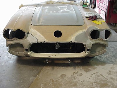
The emblem is centered on the front panel as shown.
The hole diameter is about 1/8 inch diameter larger than the I.D. of the
emblem outer trim ring.
Use the emblem gasket as a guide for locating the hole.
Good luck with your project,
Bill Huffman, Pres.
Michigan Chapter SACC
Bill
Huffman, Pres.
Michigan
Chapter SACC
From:
Larry Pearson, SoCal Chapter Advisor: Cindy: I know of no source
that gives the measurements of exactly where the large round hole goes to
accommodate the 1960 emblem. The problem is that all the front fiberglass
edges are rounded and there are no sharp edges to make measurements from. The
hole in the trunk lid is exactly the same size and shape as the nose emblem, and
they both use the exact same emblem. The hole is exactly centered between
the headlights, and all you need is the vertical measurement I own a 1958
original front clip, and a complete 1960 car, and I will make the
measurements tonight
and email them to you tomorrow.
Your painter can paint the car the way it is and add the round emblem hole later
if time is a problem. Be sure to fill in all the 1962 emblem holes before
painting the car, because none of them are used for the 1960.
Larry Pearson
*********
07/19/2020
I recently changed the engine oil and filter on my 1961 Corvette and have
noticed a slight oil leakage at the oil filter canister bolt head.
Do you know of a way to eliminate this leakage? I don’t remember leakage
at this location prior to the oil change. I am fairly certain I have
sufficient torque on the bolt and have observed no oil leaking at the cannister
to engine interface. The canister assembly is fairly new (Purchased from
Paragon in 2004). The original canister bolt to canister was not
integral (Bolt was not attached to the cannister). So I replaced it with
the Paragon canister assembly.
> Thank you,
> Mike
From:
Bill Huffman, Michigan Chapter President: Mike,
The original style oil filter cannister can be a leakers delight if not
installed properly. The rubber square x-section sealing ring at the top has to
be seated flat without twisting or humps plus the cannister needs to be
installed straight & perpendicular to the engine block sealing surface. The
original detachable cannister bolt should have had a seal under the bolt head
flange to keep the oil from leaking out the bottom.
Your integral bolt cannister should have either a seal under the bolt flange or
sealing grooves formed on the underside of the bolt flange.
Paragon has very helpful customer service people. Since you are local, why not
give them a call at 800-882-4688. I'm sure they would be happy to help you.
Regards,
Bill Huffman, pres.
Michigan Chapter SACC
solidaxlecorvettemi.com
From:
Larry Pearson, SoCal Chapter Advisor: Mike: The original bolt was
held in place with the canister shell with a spring on the inside of the
canister. The bolt did not come out separately from the canister, they are
held together. If the leak is at the bolt head interface with the canister
shell, see if you can work some Teflon pipe thread sealer tape between the bolt
head and the canister shell. This very likely will stop the leak.
On the other end, whenever I change the filter cartridge, I remove the aluminum
"O" ring retainer to remove the old O-ring at the top end. It is
difficult to remove the old rubber O-ring without doing this.
To make the oil filter change a lot less messy, I drilled a hole in the bottom
of the canister and threaded it for a 1/8 pipe plug. There is enough metal
thickness here for the plug to seal and not leak. I use Teflon tape on the
plug threads and never have had a leak. This allows me to completely drain
the old oil out of the canister so when I remove it there is no hot oil running
down my arm and onto my driveway. I only change the filter element every
other time I change the oil, and this allows me to easily drain the old oil out
of the canister. Of course this will fail in NCRS judging if the judges
see it.
Larry Pearson
**********
07/17/2020
Hello,
Need to replace m clutch cross shaft bushing on my '61. I may also have
to remove the clutch cross shaft to check the ball studs or remove the bushing
if it doesn't come out readily. Can I get instructions on both. ST-12 was
unclear in there instructions.
Thanks Larry
From:
John Spencer, Red River Chapter Advisor: To remove the cross shaft
requires releasing the tension on the cross shaft helper spring. I have
always placed a pair of large vicegrip pliers (or
medium pipe wrench) on the cross shaft itself, released the clutch
push rod from the cross shaft and allowed the cross shaft to rotate and relax
the spring. Once the spring is removed - disassemble of the cross shaft is
an easy task. take caution here - the cross shaft spring is stout - have a
good grip on the cross shaft with your pliers - make sure you can rotate and
hold the shaft with the pliers before removing the clutch push rod.
From:
Larry Pearson, SoCal Chapter Advisor:
Larry: I assume you have a completely stock system with the big assist
spring and the remains of the original bushing, which is pressed into the top
end of the cross shaft. If this is the case, you will have to remove the
cross shaft to remove and replace the bushing. Your car's clutch pedal
system should be exactly like pictured in figure 7, page 6R-4 in ST-12.
If your car is using a diaphragm type pressure plate (not original), the
heavy assist spring is gone, because it is not needed.
The procedure on page 6R-9 is correct for removing the cross shaft. Once
the cross shaft is removed, the bushing outer sleeve must be pressed out of
the cross shaft. I use a socket of the proper size on both sides to
press the sleeve out in a vice. The bushing is composed of three pieces:
the outer sleeve, a rubber insulator, and an inner bushing. The rubber
part disintegrates with age, and that is probably what you are facing.
Everything will work fine without the rubber. Press the service
replacement bushing into the cross shaft using a socket slightly larger that
the one you used to to remove the sleeve. Lubricate both ball pivots
with lots of chassis grease before reinstalling the cross shaft.
Unfortunately there is no grease fitting on the C-1 cross shaft. This
came in 1963. Use the cross shaft installation procedure in ST-12 to
reinstall it.
In my experience, the rubber insulation rapidly disintegrates, and back to
square one. Danchuck sells a two piece bushing made of Delrin that
replaces the original rubber insulated bushing. Their catalog number is
#345. I am using one of these in my 62, and it is completely trouble
free. It won't pass NCRS judging, however.
Larry Pearson
From:
Joe LeMay, SoCal Chapter Advisor:
I wrote a short article on how to fabricate a press out of a bolt and sockets.
It is in September
2019 Solid SCOOP. (Does that get distributed?)
The hardest part is compressing the gorilla spring. Remove the bellcrank
to clutch fork pushrod fitting. Use a pipe wrench on the bellcrank tube,
or a large open end wrench on the bellcrank arm to relieve the pressure the
spring creates on the bushing bolt, remove the bolt, and release the spring
pressure.
If you need the article, I can send something.
Joe
**********
07/08/2020
It seems like everyone is having questions regarding their 1962 at this time.
I have had mine now for 45 years and I have just changed my front wheel
bearings to roller bearing that i purchased from Zip. My problem is that
even though I pushed the inner races into the hub to the shoulder, I can't
seem to keep the inner bearing seal in place easily while I slide the hub onto
the spindle. If it isn't slid on smoothly the bearing seal comes off and
it can be floating in there and not allowing you to adjust the wheel bearing
properly or even to know that it hasn't stayed in place. Has anyone else
ever had this problem, or does anyone have a solution to this problem?
Thank you,
From:
Verle Randolph, Red River VP:
Compare the new seal to the old seal, are the dimensions the same?
I had a similar problem some years ago on a different car, the seal was
"similar" but just enough difference it would not stay in place.
I bought from my normal parts store, they knew me so they worked with me to
find out what the problem was. Turned out the new seal was actually made for a
completely different car. It was very similar but did not work. We looked at
several different boxes until we found the correct seals.
Verle
**********
07/07/2020
VIN number check. We have a 61 vette left to us, no title, no tag on steering
column. I understand there might be a stamp on the frame under the drivers
seat. Is there a way to check this without removing the body or cutting hole
in the floor. Thanks for any input on this matter.
From:
John Spencer, Red River Chapter Advisor: My 58 has the VIN stamped on the
frame. It is located under the driver's seat area on the top of the frame.
Depending on how much space you have between the frame and underbody, you
can see it with a light and mirror.
From:
Joe LeMay, SoCal Chapter Advisor: I checked my VIN stamp on a 1957.
It is located at midlength of the door. You will need to loosen all the
body bolts (12), and remove the five- left side nuts. Put a 18" piece
of 2X4 on the floor between the frame and rocker panel. Jack up the body
about 1 1/2 inches. Clean the top of the frame in that area and use a
mirror taped to the floor under the frame rail. With the correct lighting,
you should be able to take photos.
From:
Chip Werstein, SoCal Chapter Advisor:
Does the car have the original engine? If so the last 5 digits of
the vin will be stamped on the pad along with the engine assembly date.
However, with the tag missing it may have been a theft recovery and the original
engine may be long gone.
Chip Werstein .
From:
Larry Pearson, SoCal Chapter Advisor:
In addition to trying to get a photograph, which will be a mirror image, not
a positive, I suggest that a pencil rubbing be attempted.
Larry Pearson
From: Verle Randolph, Red River
Chapter VP:
I was able to read my frame stamp by inserting a wood wedge to lift the floor
board a little. Used sand paper to clean the frame, wiped it off and could
read VIN with mirror and light. Might help to unbolt the driver seat from
floor to make it a little more flexible.
Verle
From: Bruce Fuhrman, SACC
Secretary:
I had the same problem on my '54. In CA they have to verify the
"original" VIN # before the issue plates. Joe is right, the
VIN # is stamped on the top of the frame just below the mid of the drivers
seat. It is about 1" clearance between the frame and the body fiberglass.
I did not raise the body and inserted my finger and found the stamping. I
sanded the # and put chalk dust on the # and flat wiped it clean with a cloth.
Then as Joe said, I took a dental mirror and a flashlight to explore. I was
able to read the # and I got an "adda- boy" from the inspector at
the CHP!
Good luck,
Bruce Fuhrman
**********
I have owned my '62 for over 50 years. The top is rarely used. I
would like to know what I can lubricate the bows with that won't stain the soft
top.
Thank you ,
Bud
From:
Bill Huffman, Michigan Chapter President:
Bud,
WD-40 brand
makes a spray White Lithium grease that has a 6 inch application nozzle
that I used to lube the rotating joints in my soft top frame.
Use gentle
pressure on the release button, put a rag behind the frame to catch the
overflow and wipe off the excess grease.
Don't
overdo it and you shouldn't have an issue with the grease staining the top.
Remember, it's easier to add more grease periodically that deal with the
collateral damage of using too much.
Bill
Huffman, Pres.
Michigan
Chapter SACC
From:
Larry Pearson, SoCal Chapter Advisor:
Bud: The absolutely critical point needing lubrication is the pivot
point over the center of the side windows. Without lubrication, this
joint will seize up and bend or break in two the section that goes to the
front header when the top is raised. I do not recommend any spray grease
because it is very hard to get grease to work its way into the joints. I
use 30 weight engine oil in a 20 cc hypodermic. This arrangement allows
you to exactly pinpoint where you are applying the oil. Thirty weight
oil is thin enough that it will easily penetrate all the joints without
getting on the top fabric.
Larry Pearson
**********
7/01/2020
My 62 had the typical gasoline smell. Since
it’s almost 60 years old, I decided to replace the gas tank. I checked
for leaks in the new tank by filling it with water. No leaks. Then
I looked at Joe Calcagno’s website (RareCorvettes.com).
One of the things he does is to take out the filler tube, put the cap
on, turn it upside down and fill it with water. Good way to find leaks.
Luckily, I had 3 gas caps to try. One vented and two unvented.
Here is what I found.
1. New gas filler tubes can be defective.
I sent one back and got another - still bad. They leaked at the joint
between the tube body and the fitting on the end. The new ones weren’t
seal welded, only tack welded. Totally unacceptable. After
going through two of them, I decided to use JB Weld all around the joint on
the outside of one of the new the filler tubes. It worked! Second
time I’ve used JB Weld to fix something (last time it was the weld on the
small aluminum fitting on the bottom of the expansion tank). Works
great. I love that stuff.
2. Most gas caps leak. I used the one
that leaked the least. It was an unvented one. I then JB Welded the
rivet connection on the inside of the gas cap. The rivet holds the
handle on but it is a mechanical connection that gas can leak through. To
finally stop all leaking, I made another rubber gasket to go over the existing
gasket on the inside of the gas cap. (I just found this out after
installing everything and still smelling gas. Even a tiny leak at the
gas cap really smells). The gas cap really fits tight now.
Did some right turn 360’s with a full tank of gas. No leaks. No
smells. BTW, I’ve had an old inner tube for years that I’ve used to
make custom gaskets. Very handy.
3. Installing the fuel sending unit is tricky.
If you don’t do it right, it leaks too. I made the mistake of over
tightening the screws holding the unit on the tank. The gaskets deformed
and leaked. I also made a mistake by installing the ground wire on one
of the screws, the way you’re supposed to. If you install the ground
wire terminal on the screw, you would need an extra gasket. The steel on
steel connection between the terminal and the tank, or between the terminal
and the screw head, leaks. Joe Calcagno recommends soldering the ground
wire to the top of the sending unit, instead. I didn’t have any luck
doing this so I cut off the terminal, stripped the end of the wire and wrapped
the bare wires around the metal fuel tube on the unit. Then I used a
hose clamp to hold it in place.
From:
Larry Pearson, SoCal Chapter Advisor:
Charles. I got my first 62 in 1966, and currently have two 62's and one
60. No fumes in any on them. The proper and easy fix is to
completely seal the gas tank cover. There are three large holes in the
fiberglass area under the gas tank area. The area under the gas tank is
a high pressure area when the car is driven and any fumes from a leaky sender
gasket, a broken vent line hose, or the hose connecting the filler tube to the
gas tank will get into the car if the gas tank cover isn't completely
sealed. Use 3M Strip Caulk to seal the edges of the tank cover
perimeter to the car body. Strip Caulk is a black clay-like material
that remains pliable to allow easy removal of the gas tank cover if needed.
Strip Caulk is available in most automotive paint stores.
Gasoline leaks in the gas filler area, as well as rain water, drain directly
under the car via a rubber hose that connects to a fiberglass nipple in the
gas tank area under the drain hole to a hole in the gas tank area floor
directly under the drain hole.. If this hose is missing or broken, then
fumes from the gasoline filler area will end up in the gas tank area and into
the passenger area if the gas tank cover is not completely sealed, as
described above.
Larry Pearson
**********
06/24/20
Hello. We just recently purchased a 1960 with the 4-speed. The
speedometer does not work. The cable turns at the speedometer, but only in
reverse. I haven't looked at the driven gear yet, but was just wondering
if anyone else has seen this issue.
Thanks,
Neil
From:
Joe LeMay, SoCal Chapter Advisor:
T-10 and early M-20, 21 use a steel drive gear and plastic driven gear.
The driven gear can wear and the teeth are contacting (marginally) in reverse,
and the contact in forward is so little the speedo needle does not move.
Try replacing the driven gear with one that is the same diameter.
If that does not work- The other issue is a mismatch with the drive gear.
There are two drive gear diameters and two driven gear diameters. See
the March
2020 Solid Scoop for my article on speedo gears.
**********
06/14/2020
I would like to know the correct torque specifications for the flywheel and
pressure plate bolts on a 265 cu in engine. Also is locktite recommended
on these bolts?
Thanks,
Mike
From: Joe Lemay, SoCal
Chapter Advisor:
The specs I use are 60 for the flywheel and 35 for the pressure plate.
Use medium threadlocker. Do not use permanent.
From:
John Spencer, Red River Chapter Advisor:
Flywheel torque = 65 ft lb, clutch pressure plate = 35 ft lb. (source
- GM Chassis Service Manual)
Locktite not recommended
**********
06/13/2020
I just put a new clutch pressure plate and flywheel in my 62 Vette. I have
the transmission about 1 inch from being up to the bell housing and it is hung
up. Any help?
From:
Verle Randolph, Red River chapter VP: The usual problem is
misalignment of the clutch plate. If it is not accurately centered on the throw
out bearing the input shaft will hold the transmission an inch away.
This is how many transmission ears are broken, someone tries to pull the
transmission to the bell housing with the bolts.
Remove the transmission and look through the center of the hole and look at the
clutch plate hole and the throw out bearing alignment.
Solution is to remove bell housing, loosen the clutch plate bolts until you can
move the clutch plate and center it. The alignment tool that comes with the
clutch kit is usually plastic and does not do a good job of centering. It often
(usually???) allows the clutch plate to slip down just enough to cause your
problem.
If you have an input shaft from any Chevrolet standard transmission they work
better. If not, do your best to center the clutch plate with the alignment tool
as you tighten the lower two bolts a little. Move the tool in and out. when
centered it should move fairly easy. Keep doing this as you tighten bolts around
the clutch plate to make sure the tool moves. Also, remove the tool and inspect
the alignment visually.
It is a bother but it must be done.
I have bought many very good 4-speeds with broken ears for a cheap price.
Verle
From:
Bill Huffman, Michigan Chapter President: Lee,
you changed the flywheel. Did you check to make sure the nose bushing fit the
transmission input shaft?
1 inch is about the depth of the nose bushing.
If you did and it fit, does the clutch spline fit the input shaft freely or was
it sticky/tight?
Is the clutch spline symmetrical relative to the plates? If not, the new
clutch plate could be backward.
Did you use an input shaft installation tool to align the flywheel/bushing/
clutch plate/pressure plate assembly before tightening & torqueing the
pressure plate to the flywheel?
Good luck on your installation R & R,
Bill Huffman, Pres.
Michigan Chapter SACC
**********
06/09/2020
Next question: I replaced all 22 front suspension/steering joints when I did
the full restoration a few years ago. Now, 3 of the 22 joints will not
accept new grease and I have confirmed the zerk fitting is passing grease by
removing it and confirmed grease does get through the zerk. So something
appears to be blocking grease passage. One is inboard tie rod joint the
other two are the LH and RH aft upper control arm joint.
Ideas on what I should try to resolve the issue?
Thank you,
From:
Joe LeMay, SoCal Chapter Advisor:
I am having the same issue with the four lower inner fittings. I have not
disassembled the joints but the zerk fittings will pass grease. This is a
complete rebuild done in 2014 and there is about 5000 miles on the car.
I grease it with the car jacked high enough to get under with a creeper.
If I hold the grease gun fitting to the joint as I do for all the other
fittings, all the grease gets rejected. If I brace myself and push the
gun as hard as I can into the fitting, I can get a small amount of grease to
come out of the joint. I am pushing the gun into the fitting with a lot
of pressure; as much as I can create.
I have not tried an air pressure grease gun. I would expect to get more
grease into the fitting as I can push the gun with both hands and not have to
operate the lever. With air pressure and two hands, I hope to clear
whatever it is that is creating the blockage.
From: Verle Randolph, Red
River Chapter VP: I have had this
problem before on a Solid Axle and another vehicle.
One thing that helped me was to remove the zerk and squirt some lubricating oil
in the hole. Jack car up, remove tire, jack stand support. I found better
results by squirting oil several times over two or three days.
My theory is the grease hardens over time, possibly by losing volatile
ingredients. The lubricating oil softens the grease making things work better
and allowing grease to be added through the zerk.
Only other option I know is to dismantle and redo.
Verle
From:
Larry Pearson, SoCal Chapter Advisor:
Mike: I have six early GM cars (three of them are C-1's) with the kind
of suspension our Corvettes have. All the A-arm joints are
"metal to metal" with very tight tolerances when they are new, like
yours are. When the joints get some wear, in my experience, it becomes
easier to inject grease into them due to the increased tolerances. I
have some joints where it takes all my strength to inject grease into them,
but slowly some grease expels from the back of the joint indicating that the
joint is getting properly greased. That is all you can and need to do
with the difficult joints. We are told by GM to grease these suspensions
every 1000 miles. Last resort - Go to a fitness center and train to
improve your upper body strength, and that will make it easier to grease your
car..
Larry Pearson
**********
06/08/2020
I can't figure out how to put the chrome trim pieces on the glove box door.
These two pieces are approx. 12 inches long, 1 inch wide and are positioned
vertically when the door is closed.
I've had this car since 1973 and a '56 before it for 7 years. I've
assembled this door twice before when painting it but can't seem to get it
together this time.
Thanks for your help,
Jim
From:
Joe LeMay, SoCal Chapter Advisor:
The seat separator panel is attached to hinge by the middle bolt holes of the
panel and the top holes of the hinge. It uses #8 clutch head screws.
These screws would be painted body color. The moldings are attached with
four- #8 philips screws through the bottom and top holes.
Parts suppliers will have the trim hardware to retain the molding. It
is the usual hardware to retain body molding. Paragon has the typical
hardware.
The short lower stainless steel trim
moldings are bolted and retained with hex nuts and star washers.
**********
06/07/2020
After draining the radiator and engine block, how do I install 16 new quarts
of coolant? It only seems to accept about 10 quarts.
Thank you,
Michael
From:
John Spencer, Red River Chapter Advisor: Even if you open Block Drains (if
you have them) you don't completely drain the block. If you're wanting to
remove all the old coolant, you have to flush the block. This will dilute
what coolant is remaining in the block and if you flush it long enough - replace
the residual coolant with clear water. When adding coolant back - simply
anticipate the amount of clear water in the block to establish your desired
concentration of coolant-to-water.
Note: Heater core will hold 1 Qt.
From:
Verle Randolph, Red River Chapter VP: When filling an
empty radiator and block you will have a lot of trapped air. Pour in as much as
you can. Leaving the radiator cap off, start the engine and let it run, when the
thermostat opens the level will fall. Keep pouring in water/antifreeze until it
is full. You may have to top off a few times. After a drive where the engine is
thoroughly warmed up. Turn off, let cool down then check the water level, ad as
necessary. You need to open the heater control valve so it can drain or fill.
The Corvette Servicing Guide -P 14-9 at bottom, says 16 qt w/o heater, 17 qt
with heater.
Verle
From:
Chip Werstein, Socal Chapter Advisor:
Mike,
Verle is .most likely correct in his diagnosis of your problem. I
have been aware of potential air lock problems when filling cooling systems for
many years but have never experienced it. I drill two 1/8 inch holes in
the thermostat thin metal mounting flange. This prevents the system from being
sealed up which allows trapped air to escape thereby preventing air locks. Give
it a try.
Chip Werstein
**********
06/05/2020
My
question pertains to 56-57 Corvettes, if the Saginaw transmissions were cast in
Saginaw where were they assembled?, St. Louis. Same with the
rear ends casting in Detroit and assembled in St. Louis, or that is what I read
somewhere who knows where do you have any info on that one?
Thanks,
Kermit
From:
Joe LeMay, SoCal Chapter Advisor:
Although it may be referred to as a Saginaw transmission, there is not such
thing. Muncie 318 transmissions were produced for many years. The
main case that was used in Corvettes was cast in Saginaw. Passenger car
main case was cast in Tonawanda. There are very few ways to tell them
apart.
If you are trying to get your Corvette back to stock appearance, you will want
a Saginaw cast case and gears with a 2:20 first gear ratio. There is
also a Muncie 319 that is a 3 speed with overdrive.
That did not answer the question on where it was assembled, but maybe someone
has that.
From:
Verle Randolph, Red River Chapter VP:
There was a foundry, Saginaw Metal Casting Operations Saginaw, Michigan
1919 , where cases were cast and assembly was done in the Saginaw Transmission
Saginaw, Michigan.
Metal casting for power trains. Engine Blocks. Crankshafts
Manual Transmissions, Originally made the Saginaw 3 and
4-Speed manual transmissions.
The old Saginaw plant was torn down in 2019.
I believe the Corvette plant in St Louis did no major assembly on mechanical
parts. Those parts, engines, transmissions, rear ends, etc came ready to be
installed. The plant did add accessories to those assemblies.
Verle
**********
5/31/2020
Could you clarify something
Re: 1957 Airbox corvettes and exactly what was the factory assembly reference
number for the car option
There seems to be confusion :
All the literature of every type refers to the 1957 Corvette Airbox cars as
OPTION : RPO 579E
As delivered, the car came with the RPO 579E engine and a long
list of other factory-installed pieces that completed the RPO 684
Heavy Duty Racing Suspension etc
The
Corvette Restorer Msgazine : 1957 RPO 579E TACHOMETER 9 2 FALL 1982
page 19 in conjunction with Wilson Swilley article. . He says it is
from Factory Production specifications
THE FACTORY
ASSEMBLY MANUAL JUST SAYS RPO 579 with no letter after it
There apparently references to RPO 649D being the air-box
RPO code in nternal
Duntov document. and also on facebook (i.e. registry of Corvette Race
cars ) a copy of a dealer invoice for one of the "air-box"
corvettes were the line reference on the dealer invoice for the
$726.00 air-box option is RPO579D
So
what is the correct terminlology :
(a)
was RPO 579D the factory reference for just the Air-box option alone
(b)
was there an RPO 579E option before the airbox option (note: Noland
Adams book: GM
instructions for mounting the RPO 579E tachometer)
(c
) was there a change in RPO number during year
THEREFORE
QUESTION IS :
What
exactly does RPO 649 E reference to in terms of factory documents
What
exactly does RPO 649 D reference
to in terms of factory documents
Thanks
for clarification in this matter
William
From: Tom Parsons, Red River Chapter FI expert:
I’ll try to answer the questions as best as I can which were submitted by
William Keogh. Can someone add the people which were listed in the original
email that are not included. I could not get their address to attach.
BUT, the very first issue that needs to be addressed is RPO579E.
THERE IS NOT, AND THERE NEVER HAS BEEN AN RPO579E---------PERIOD!!!
Somehow, someway, back in the stone ages, SOMEONE incorrectly listed the
“Airbox” option as RPO 579E----------------AND IT HAS JUST STUCK ALL THESE
YEARS-----------------INCORRECTLY!!! The correct option number for the 1957
Corvette with the fresh air duct for the fuel injector is RPO 579D.
That is what it was in the beginning, and always has been. The publications,
“Armchair Experts” and subsequent listings for RPO 579E have been WRONG
FOR OVER 60yrs!!!!! Back in the 50s when I first became aware of
fuel injected Corvettes and in the 70s when I finally got a chance to become
involved with FI, the “E” never actually made sense to me, but I could
never come up with a reason for it. Fast forward to 2007 and Key Kayser’s
books (Vol I and Vol II on fuel injection). For fuel injection aficionados, if
you do not have these books, you are missing the boat! Once and for all, Ken
has cleared the air regarding RPO 579D (erroneously “E”). Not only does he
totally clarify the misconception, but he does it with GM documentation. He
also clarifies some additional misconceptions. ALL listings for the fuel
injected engines with the hydraulic cam have also been reversed. RPO 579A is
the3sp (or manual transmission) RPO 579B is the Powerglide. And an additional
support for the 579D as being the correct RPO for the 57 Airbox, the listings
for 58-59-60 with a solid lifter car are RPO 579D. More support that RPO 579E
for 57 was, and always has been wrong!!!
Now, back to RPO 579D. MOST people here probably know that it was more than
just a SOLID LIFTER ENGINE with a special duct to direct
cooler to the injector. It was a package-------------IT ONLY CAME ONE
WAY! Within the pkg was the air HAND LAID fiberglass air duct
for the injector. It only came with a manual transmission (MOST PROBABLY all
were 4sp), positraction, NO heater, NO radio, 5.5in (NOT 5.0in) wide wheels,
heavy duty brakes, special ducting for direction cooling air to the brakes, 5
instead of 4 leaves in the rear springs, HD front (and shorter) springs,
thicker front sway bar, HD shocks (the rear cross member was modified for
mounting the rear shocks), a unique FI ignition distributor (908) with a tach
drive fitting that turned a plain, AC 8000rpm tachometer which was mounted on
the steering column. The tach in the center of the dash was eliminated and the
hole was covered with a front/rear emblem-----------------------WITH ONE
EXCEPTION------------ 57 VIN 4007, restored by Bill Connell several years ago,
which was the FIRST production built Airbox car, had the hole covered and
finished smooth with a piece of fiberglass. There was a ONE ONLY fairing which
covered the steering mounted tach. On the assembly line for these VERY FEW
special cars, it was determined to be too time consuming and too much trouble
to cover the center hole for the regular tach, thus, the use of a front rear
emblem to cover the hole.
SOOOOOOOOOOOOO, where did I learn all this? Nothing magical. Ken Kayser has so
thoroughly and expertly provided these details (AND MUCH MORE) in his books,
plus supported it with GM documentation, and as I mentioned above, his books
would be a valuable addition to anyone’s Corvette library. When I got his
Vol I and started reading it, SO MANY unanswered questions just begin to fall
into place----------------------just one example, the 5 Cadillacs with fuel
injection and the one Oldsmobile with FI. Of course, I presume everyone knows
about the 57-58 Pontiacs with FI which was a regular option.
I am not familiar with any option 649D or 649E.
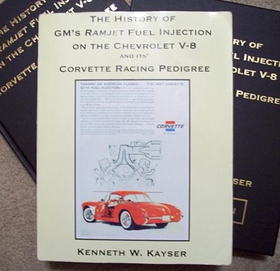
The number of fresh air
ducts (airboxes) built was 50. THERE IS NO SURVIVING GM DRAWINGS OR
DOCUMENTATION FOR THEIR CONSTRUCTION, BECAUSE IT GOT DISPOSED
OF!!!!!!!!!!!!!!!! Per Ken Kayser. What a shame!!!!!!!!!! Even though 50
airbox ducts were fabricated, only 43 cars were built with an airbox FI pkg.
So, where did the other 7 ducts go??? Well SOME of them have been accounted
for. One (a 48th car) was factory installed, BUUUUUUUUUUUT, the production
order was changed to a 2x4 engine (FI was removed and replaced with 2x4s) and
a major portion of the duct was sawed off! (MANY years ago, 70s, it was
rumored that car was in Arkansas, I never saw it) That leaves 6 unaccounted
ducts. A SACC member (John Neas in Tulsa) has one of the unaccounted for ducts
on his 57 FACTORY RPO 579C car. It was delivered to Rosenthal Chevrolet
WITHOUT an airbox (and the tach was in the dash). About 2-3wks after delivery
to Rosenthal, a complete Airbox pkg was delivered and installed on John’s
car. So now that leaves 5 unaccounted for ducts that were fabricated. One of
them MAY, repeat, MAY be on my 56. I just do not positively know the actual
source of my airbox. I bought it about 30yrs ago from someone--------------AND
IT APPEARED TO NEVER HAVE BEEN INSTALLED (NO installation holes were in it).
By the way, the fresh air duct (airbox) on the SR2 cars is custom made for
those cars. It is totally different from the ducts installed on the production
Airbox cars.
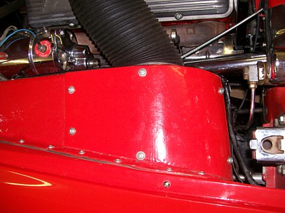 The picture of the red airbox is my “built” 56 “579D” car. It has
all the 57 579D components EXCEPT the ducts going through the rockers for rear
brake cooling.
The picture of the red airbox is my “built” 56 “579D” car. It has
all the 57 579D components EXCEPT the ducts going through the rockers for rear
brake cooling.
I probably have not answered all the questions about the 57 Airbox option, and
if there are more questions, I’ll see what I can answer.
**********
5/31/2020
I
have a 1962 Corvette 327 340hp 4 speed matching , the car sometimes cuts out
while driving, it loses power and powers up again while driving, sometimes it
looses power and just quits and will not start until it sits a while and cools
down ??
What
do I check ?
How
do I join your organization ??
John
John,
Let's answer the easy question first.
Regarding your car issues, I would suggest a couple things.
1) Use only premium gasoline as a minimum and 100% gasoline 90 octane with
lead additive & octane booster as required.
It sound like your carburetor is "boiling over"
and flooding the engine. Higher octane helps solve that.
Hardened valve seats in the heads eliminates the need for
lead additive.
2) Recently, two of our chapter members encountered similar running issues.
One made it home, the other got flat-bedded.
In both cars, a 1959 & a 1960, the coil was defective
and ran perfectly after that one part change.
Good luck with your car,
Bill Huffman, Pres.
From:
Joe LeMay, SoCal Chapter Advisor:
I had the same problem. Would let it sit when hot. Then it would start.
One day after cooling, it would not start, and there was no fuel in the
carburetor. The fuel pump was failing and finally needed to be replaced.
When you replace it, use the original configuration inlet and outlet (and
maybe original part number pump). It is a good opportunity to correct
some other items with the fuel lines if needed.
From:
Verle Randolph, Red River Chapter VP:
For a cheap and easy test install a known good ignition coil and see if that
makes any difference.
Water in the fuel can cause the engine stall, then restart while still moving.
As mentioned, lack of fuel. Could be fuel pump, partial blockage in tank or
line.
Verle
From:
John Spencer, Red River Chapter Advisor:
This could be a number of problems, but from your description - I would
suspect the coil. A defective coil will often fail in one of two modes, or
both; 1) the broken coil (wire coil) becomes intermittent - it will quit firing
for no reason and then start firing as sudden as it stopped. 2) as it heats up
it will fail and cease to fire until it cools down and remakes contact. This
is an easy fix - replace the coil and see if the problem goes away, if not at
least you know you've eliminated one possibility. All the other
possibilities are not so easily fixed. They are probably in the
carburetion or fuel delivery. Things to investigate; does the stall
occur in a turn or at a totally random time. (Left turn is carburetor), when the
stall occurs - does it seem to be the lack of fuel (fuel pump, or filter) or
does it seem to be flooding (restarts with footfeed floored = carb adjustment).
-John
**********
5/30/20
There are special rivets that are on the door latch mechanism that I was going
to fix the assembly with. Are the rivets available or will the assembly need
to be replaced?
I’m best corresponding on my home email instead of my work address, but I
have a photo of what I’m talking about attached to this message.
Thank you.
Jim
From:
John Spencer, Red River Chapter Advisor:
I
don't know of any source for the Door Latch mechanism rivets. I'm sure you
could find rivets that would work from a rivet supplier, but I don't believe the
new mechanisms are terribly expensive. I would replace the whole
mechanism.
**********
5/27/20
Steering,
I have excessive free travel when I turn all the way right or left what would
cause this?
Richard
From: John Spencer,
Red River Chapter Advisor: This
is a curious problem. The steering box on a C1 is designed to have zero
lash (play) at the high point (center position). As you turn the steering
the play between the worm gear and the sector shaft roller increases. This,
however, is not suppose to be excessive. In a worn steering box it's all
but gone; as you tighten the worm gear / sector shaft engagement at the high
point (where the worm gear has its most wear) to eliminate play - you
decrease the designed play at the steering's extremes where the worm gear
experiences less wear. Attempting to adjust the play out of the center or
high point often yields a binding of the steering at the extremes not excessive
play. I would go through the steering box adjustment procedure and verify
the play exists in the steering box. This procedure can be found in
Chevrolet's Corvette Servicing Guide ST-12. Steering adjustments are found
in Section 9, the guide which can be found on-line.
From: Verle Randolph, Red
River Chapter VP:
I would do a complete inspection of the front suspension and steering.
Excessive play in steering could be any of a number of problems.
A-frame moving, tie rod ends, idler, spindle bushings, steering box....
Verle
From:
Joe LeMay, SoCal Chapter Advisor: You
need a copy of ST-12 and a scale that will measure a pull force of 0-3 lb.
First be certain the steering wheel is centered using the indicator mark behind
the horn button. Adjust that with the drag link or tie rods. Adjust
your steering box exactly as described in ST-12. It worked for me.
**********
05/20/20
I
recently purchased a used front sway bar from a 1961 Corvette. I was with the
understanding this should have a diameter of 1” but when I measured it the
diameter is .805
Would
you know the correct diameter ?
Thank
you
Joe
A
From:
Verle Randolph, Red River Chapter Vice President:
From old GM parts manual, .8125 for 1960 to 1962.
**********
5/13/20
Sir’s,
I
have a question; Where might I find some pictures of the underside/back of
the dash on my car. And BTW I just sent my application for membership in today and
was unaware of your existence as a club.
Thanks
in advance and I’m sure with your vast knowledge of several members there is a
wealth of information about these cars.
Kermit
From:
Bill Huffman, Michigan Chapter President:
Kermit,
The 1956-57 Corvette Assembly Manual has the illustrations you're looking for.
Every Corvette owner absolutely needs a copy for their year car.
Bill Huffman, Pres.
Michigan Chapter SACC
From:
Joe LeMay, SoCal Chapter Advisor: If you are planning to have it look as
original,
I have a 1957 that I plan to remove the gauges and replace all the wiring
connections as original
My resources are my 1957 AIM electronic file that was put together from several
resources. The
file size is huge so it cannot be sent. There is one internet site that
has them, (http://earlycorvettes.com).
1956-7 Judging Manual, and go to the NCRS Discussion Board. You can search
for photos from
members who posted there.
Joe
If
you are planning to have it look as original-
I have a 1957 that I plan to remove the gauges and replace all the wiring
connections as original. My resources are my 1957 AIM electronic file
that was put together from several resources. The file size is huge so
it cannot be sent. There is one internet site that has them (
http://www.earlycorvettes.com)
.
1956-7 Judging Manual, and go to the NCRS Discussion Board. You can
search for photos from members who posted there.
Joe
From:
Larry Pearson, SoCal Chapter Advisor:
Kermit: Unfortunately, most 1957 Corvettes have gone through a period
when they were, essentially, worthless and the people who acquired them had
little regard to originality and made a lot of modifications to them.
Your best source for the information you are seeking is to examine an
original unrestored car. In NCRS, these are called "Bowtie"
cars. Maybe you can find one of these in the area that you live in
through NCRS, If you live in the Los Angeles area, I can help you with
this. Otherwise, attend NCRS and SACC events and see if you can find
what you are looking for.
Larry Pearson
**********
5/13/20
Hello,
If this question has been asked before I apologize. What grease do
you reccomend when assembling and maintaining the C! front supension.
Thanks For your Tech page,
Steve
From:
Verle Randolph, Red River Chapter VP:
I use the "standard" heavy chassis grease used on all car in the
50s, 60s, 70s, ....I just looked at a couple of tubes and did not see a
specific designation. Being paranoid I regularly grease the front end, all 22
zerks.
On long road tours I usually have the car greased about every 750 or so miles.
That is probably more than necessary but I don't have trouble with the front
suspension wearing out.
I replaced the ball bearings in the front hubs with tapered bearings, they
last better.
The obvious ones to keep lubricated are the king pins and the A-frame.
From
Bill Huffman, Michigan Chapter President:
Steve,
You should be able to locate a digital copy of 1953-1962 Corvette Servicing
Guide ST-12 online.
Page 0-7 contains Illustration Fig 10 which shows all chassis lubrication
requirements.
The answer to your question is a GM approved Chassis Lube and all 21 fittings
should be lubricated every 1000 miles.
Bill Huffman, Pres.
Michigan Chapter SACC
From:
Larry Pearson, SoCal Chapter Advisor:
Steve: My response goes beyond your question, but you should find it
useful. I have many years experience servicing General Motors front
suspensions, and have seen it all.
First, you should have a copy of Corvette Servicing Guide, Publication ST-12.
This publication was prepared by Chevrolet in 1962 and is the only official
shop manual for C-1 Corvettes, and is available from all the major Corvette
parts supply sources. This publication is a "must have" for
all C-1 Corvette owners.
Except for ride height, your front suspension is identical to that used on the
1949-1954 Chevrolet sedans. All the bushings are
"metal-to-metal" with a very limited ability to store grease.
Therefore, Chevrolet recommends that the front suspension lubrication points
(22 of them) be greased every 1000 miles using chassis grease. The 1000
mile interval is extremely short by today's
standards and, in my experience, you can go 2000 miles without causing undue
wear. Chassis grease is available in cartridges that fit in a standard
chassis grease gun. I recommend that you outfit your grease gun with a
rubber hose that is sold separately. This greatly assists in accessing
the hard to reach grease fittings.
When greasing the fittings, wipe off the tips of each one to prevent the
injection of abrasive dirt before greasing with the gun. I keep my front
suspensions clean by taking a putty knife to scrape off all the old grease and
road dirt. I have a 5 gallon metal can filled with about two gallons of
Mineral Spirits and use an old sock to do the cleaning. Your suspension
may have so much old caked grease and dirt that you cannot find the grease
fittings. The upper A-arms each have two inner grease fittings that are
hard to see, but must be greased. The king pins each have two fittings,
two facing forward on one side and two facing rearward on the other.
Consult ST-12 to see where all the fittings are. The front center pivot
(steering idler) ball bearing is permanently lubricated on Corvette.
The wheel bearings should be packed every 10,000 miles with Sta-Lube Heavy
Duty Drum Brake Bearing Grease (in the green can), This is the only
satisfactory grease to use for ball bearing wheel bearings. Dip each
bearing in solvent and use a heavy paint brush to work out all the old grease.
Carefully inspect the balls for evidence of spalling (failure). Each
ball must be shiny and smooth. Inspect the inner and outer bearing
races for evidence of flaking. The surfaces must be completely smooth.
Pack the grease into each ball bearing assembly by hand, making sure that
there no voids. After installing the bearings, tighten the castle nut to
30 ft-lbs and spin the hub to make sure the bearings are seated. Then
back the nut off until the cotter key clears the first hole in the spindle and
insert it and bend the ends to keep the key in place. If your grease cap
has a static collector in it, cut off the outside tail of the cotter key to
prevent it from engaging the spiral on the collector and destroying it.
Ball bearing wheel bearings must be pre-loaded. Tapered roller wheel
bearings must never be pre-loaded. The castle nut must be slightly loose
with tapered roller wheel bearings.
Larry Pearson
**********
5/12/20
Recently purchased a 1961 corvette but
the spears were in the trunk. And it seems last time painted the holes were
filled and painted over. I have got all parts for reinstall but wondering if
there is a pattern to putting them back on the car. Don’t want to willy
nilly a $60k car
From:
Bill Huffman, Michigan Chapter President:
Randy & Doc,
First, let's define our terminology.
1958- 1961 Corvettes have 3 Side Spears on each side cove.
Corvette Central sells them as individual parts or as complete kit 331215.
1958 Corvettes have a pair of Trunk Strips that Randy doesn't need.
Assuming whoever filled in the side cove mounting slots merely filled them
with body filler & a putty knife, the original mounting slots/holes should
be obvious by inspecting the coves on the inside of the panels. The splash
shields on the inner fenders and the kick panels in the cabin will have to be
removed to gain access. Use a small drill from the inside to open the holes
then use a small round or flat file regain the original size.
Please, go buy a 1961 Assembly Manual & read it before you start cutting.
Bill Huffman, Pres.
**********
5/12/20
Were bell housings and transmissions painted or just left unpainted in 1956?
Thank you, Michael
From:
Larry Pearson, SoCal Chapter Advisor:
Michael: The cast iron transmissions were installed on the engine
after the engine was painted red with the bellhousing attached. Then
the cast iron transmissions, 3 sp, 4 sp (late 1957), and Powerglide, were
painted with gloss black chassis paint with the engine/transmission in the
chassis. There was black overspray on the bellhousing. This was
the way my unrestored 1960 was done. This final blackout painting was
done with the engine and transmission mounted in the chassis just prior to
the body drop. The brake drums brake lines, one side of the brake
master cylinder and brake line to it, the front suspension, the rear
leaf springs, and the exhaust system were all painted with chassis black
paint. It wasn't pretty. It was done as a rust preventative.
The paint quickly burned off the exhaust manifolds and the exhaust system.
There is an assembly line photo in the book "Birthplace of
Legends" by Peter Licastro that shows this. I can't find my
copy so I can't tell you what page it is on.
Larry Pearson
**********
05/11/20
Were bell housings and transmissions painted or just left unpainted in 1956?
From:
Joe LeMay, SoCal Chapter Advisor:
Hi Michael:
1956 Corvette engine color is red except possibly the last few weeks of
production, which may be Chevy Orange; Manual
transmissions use a cast-iron bellhousing and is painted engine
color. There were several items that were bolted to completed engine
and they were painted as an assembly including the water pump, oil pan,
balancer, and bell housing. Items that were not bolted onto the
assembly were many times black, such as the road draft tube and generator
adjusting brace.
The red color is similar to Ford Tractor
Red.
Joe
**********
05/10/2020
Can the powerglide transmission on a 1954 Corvette be removed without removing
the engine?
Thanks,
From:
Bruce Fuhrman, SACC Secretary:
Yes, you can remove the Powerglide transmission on the '54 without removing
the engine.
Bruce Fuhrman
**********
05/10/2020
I need to put in my lock assembly for trunk on 1960 corvette. I am having a
rough time trying to attach the retainer clip which holds the lock cylinder in
place. Should I remove the corvette emblem to get better access to the lock
assembly? Thank you for your assistance. Jim
From:
Bill Preston, Red River Chapter President:
Yes remove the emblem. You are fortunate to have that opening for the
emblem to give you access
to install the retainer clip. That's the reason they designed that emblem
that way. I have a 1957 and
don't have that extra room to work. It's REALLY hard to get that retainer on
a 56-57.
Bill Preston
**********
Dear Solid Axle Corvette Club:
I hope you can help me, The problem concerns body segment being fitted
properly: Hood adjustment so front of hood is flush with fender on 1960
corvette
From:
Larry Pearson, SoCal Chapter Advisor:
I assume that the question is: How do you adjust the hood on a 1960
Corvette to fit the opening and to align the hood with the front of the car
and the side fenders?
Refer to figure 6 on page 11-2 in Corvette Servicing Guide, Publication ST-12.
This publication, prepared by Chevrolet in 1962, is the only official shop
manual for C-1 Corvettes, and is available as a reprint from all major
Corvette parts supply sources. This publication is a "must
have" for all C-1 Corvette owners.
The hood hinges have slotted mounting holes where they attach to the hood (two
bolts) and the radiator support (three bolts). The three bolts attaching
the hood hinges to the radiator support allow for up and down adjustment of
the hood and the two bolts attaching the hinges to the hood provide fore and
aft adjustment.
The rear lock assemblies mounted on the rear of the hood also allow up and
down adjustment of the hood at the cowl. There is a screwdriver slot of
the tip of the hood lock assembly for this adjustment. Also, the
rubber bumper on the catch assembly mounted on the firewall is adjustable up
and down.
If your Corvette has had front end collision work improperly done, it may not
be possible to achieve a perfect fit of the hood to the body.
Larry Pearson
From:
Bill Huffman, Michigan Chapter President: Jim,
As designed, the hood height is pretty much locked in once the hood hinges are
bolted to the underside of the hood and radiator support bracket.
There are actually two separate adjustments:
1) There are 4 (2 on each side) inner fender to radiator support bracket
screws/fender washers that lock the entire
front clip height in place on both sides relative to the hood.
2) There are steel & rubberized fabric shim packs/screws that help
raise/lower the support bracket relative the chassis
& helps lock in the hood height.
Note: This is IMPORTANT !! All front bumper bolts and support bracket to chassis
shims/screws must be LOOSE before attempting to raise the front clip to match
the hood height. Loosening the inner fender to main body/cockpit screws at the
rearward edge on both sides might help ease some strain also.
Good luck & be careful,
Bill Huffman, Pres.
Michigan Chapter SACC
**********
I have been told the V-8's could have come from the factory with either 10
inch or eleven inch flywheels and clutches. Is that correct? I am
trying to get the correct size for my 1956. I have had a 3789733 casting
flywheel for some time and had planned on using it. I looked in a 1973
GM parts book and under flywheel it says, second design, 10 inch clutch, but
when you look up clutches, it says 10.5 inch clutch. I look in catalogs
and some have 10 inch 10 1/8 inch and some have 10.4 inch. Hemmings
Motor news seems to say either 10, 10.5 and 11 inch. After all of what I
have read I am thoroughly confused. What would be the size that was used
from the factory and what is the recommended size to use?
From: Chip Werstein,
SoCal Chapter Advisor:
My 1964 chevrolet master parts book lists flywheel casting
number 3729004 for all 55 thru 62 corvettes as well many other 55 thru 64
passenger cars and trucks. The actual clutch diameter is referred to as 10 or
10.5 inches. There is an 11 inch listed for 55 thru 64 passenger and
trucks....cast 3714463 for hd applications, but not for corvettes.. I can not
find your flywheel 3789733 listed anywhere.
Chip Werstein
From:
Verle Randolph, Red River chapter VP:
3789733 is an 11" flywheel for late 60s and 70s. Used mostly on big
blocks.
Not for Solid Axle Corvettes.
Verle
**********
Hello, I am finishing up with rebuilding my front suspension which I stopped
work on seven years ago. Back when I installed the new king pins, I think that
it was the owner of the machine shop that replaced my upper inner bushings in
the spring towers, that suggested putting locktite on the outside of the lower
king pins bushings to keep them from turning. The more I learn and the more i
think about it, I think that this was probably the wrong thing to do. Can anyone
tell me whether I did the right thing or wrong thing in putting locktite on
those bushings? I know they call them free floating bushings. My second question
is how can you tell when an upper control arm is no longer serviceable? My new
bushings, when inserted into the outer side without turning in the threads and
without the outer shaft in place, will go into the hole leaving a thread or two
showing on the outside. They seem to tighten to the prescribed 35 foot pounds
when it is assembled with the cross shaft in place. It is just that I have had
it apart a few times and possibly by other owners as well. If this one side is
in need of being replaced, I would rather do it at this point. I do have another
control arm that I could replace it with, but it is pitted and doesn't look so
nice as my one that came on the car. Thank you for all of the help.
From:
Verle Randolph, Red River Chapter VP: Ref: 1953-1962
Corvette Servicing Guide
Technical Service Department
Chevrolet Motor Division
Installation
"When replacing the kingpin floating bushings it is not necessary to ream
them to size as service bushings are machined to finish dimensions.
However, when replacing floating bushings, care should be taken to make sure the
oil grooves in the bushings line up with the lubrication fitting hole in the
steering knuckle.
These bushings should be free both on the kingpin and in the steering
knuckle."
This would suggest that locktite is not appropriate for the bushings.
I am curious why the shop suggested locktite.
Verle
**********
hi, What color is the metal axle positraction tag? Thanks. Steve
From:
Larry Pearson, SoCal Chapter Advisor:
Steve: I have a 8x10 glossy print from Petersen Publishing Motor Trend
road test taken of the rear axle of a 1961 Fuel Injected Corvette with the car
on a lift. The series of 31 prints I purchased from Petersen in the late
70's shows all aspects of this car: front, rear, interior, trunk, engine
compartment, interior and the entire chassis of the car. This car has
1519 miles on it, so it had been driven, and the chassis was not like new
anymore. You can even clearly see the grain on the steering wheel.
These were high quality pictures taken with a large format camera.
The Positraction metal circular tag and the plug were unpainted. It is
possible that these items were removed for inspection of the contents and the
chassis blackout paint was removed at that time, because it seems plausible
that these items would be painted chassis black. Also, there is a large
yellow (It was yellow on all three of my cars) circle of paint circling the
fill plug area and a large white "X" grease marked under the yellow
paint.
Larry Pearson
From:
Chip Werstein, SoCal Chapter Advisor: Steve,
It is my belief the circular tag was raw steel....possibly painted over during
the blackout process. I always cad plate mine. NCRS has never deducted anything
for the plating.
Chip Werstein
**********
Hi guys , i have a 1957 corvette and i am looking for the correct headlights
. it is" a t-3" triangle in the middle with pebble grain, on the
bottom it shows " guide" on the bottom and above that it shows "
sealed beam" in small letters. in 1956 it had large words " sealed
beam". can you folks help me locate 2 headlights.
thank you
bob
From: Larry Pearson, SoCal
Chapter Advisor:
Robert: Corvette Central sells "correct" reproductions of the
1956-57 headlight bulbs. Of course, these are not "exact"
reproductions. The originals had a small bright silver half moon shaped
shield inside in front of the filaments. The reproductions have a larger
fully round black cone shaped shield with a slot across the center. I
assume that NCRS accepts the reproductions.
Larry Pearson
From:
Joe LeMay, SoCal Chapter Advisor:
Hi Bob
Per the JM
Headlamp bulbs must be matching Guide T-3 design; with pebble-grain (not
vertical ribs) within
triangle. SEALED BEAM 3/8" and 1/4" high lettering were both used
throughout the 1956 and 1957
year models.
The other challenge is they are non-DOT. I would like to get another
set myself.
Joe
**********
Having a tough time locating replacement hinge pins for a 1955 Corvette. Any
help appreciated.
From:
Verle Randolph, Red River Chapter VP: Ebay vender for
early Corvette parts partsqueen responded to my message:
"New message from: partsqueen Top Rated Seller(9,765Green Star)
Hi There, I have the door hinge shims and plates and a few door hinge pins and
maybe a few bushings and not many"
Her parts store is on ebay.
If you deal with her make sure to clarify what you are getting and what
condition.
She often has very hard to find parts.
If the pins don't show on her store, click on a part and send message about the
pins.
Verle
*Note: From: Web Editor: When you venture on ebay
you are never sure who you are dealing with. They may not have a lot of
expertise, plus their idea of quality might not be the same as your idea of
quality. They may send you something that differs from what you asked for.
As Verle said above, make sure you verify the part and condition.
I just found another source for early parts.
http://www.carolsclassiccorvettes.com/
Lloyd Miller, a noted restorer of 53-55 Corvettes said he has had good luck with
them.
I have not asked them about hinge pins.
Another issue, 55 hinges are aluminum. You have to be careful to not break them.
Verle
(Note: From Web Editor: The same disclaimer noted
above applies.)
**********
Larry here from the Solid Axle Club. I have a '61 FI and the welch plug
on the side of the meter is seeping fuel. Wondering who may have
experience and be able to seal or replace the plug?
From:
Larry Pearson, SoCal Chapter Advisor:
Larry: They all leak because the zinc casting cold flows causing the
plug to loosen up and leak. This is not a problem with the early sand
cast aluminum fuel meters that use a pressed-in aluminum plug. Don't try
to replace it. The factory pressed it in with a special fixture that no
one I know has. If it just seeps, I recommend living with it. If
the plug is so loose that it might pop out, you must epoxy it in place. If
appearance doesn't matter, seal it with JB Weld. JB Weld is not affected
by gasoline when it is cured. JB Weld sags until it cures. Use wax
paper to hold it in place while it cures. Or remove the fuel meter (or
the entire unit) and lay it on its side while the JB Weld cures.
If appearance does matter, you will have to remove the fuel meter top cover
and try to compress the existing welch plug using large Channel Lock pliers or
a "C" clamp and a steel bar or thick washer on the inside of the
casting for support. I have not tried this. Do not use
a hammer. Be very careful not to break or warp the casting.
Do not use Cyanoacrylate (crazy glue) or RTV Silicone sealer. These
adhesives are not compatible with gasoline.
Larry Pearson
**********
Due to illness, my 1959 sadly sat
for too long. Upon starting it, the
brake pedal went straight to the floor. The master cylinder is dry (and
a little rusty). There is no sign of a leak anywhere underneath or
around the lines or cylinder. Any ideas what may have happened.
I run
Dot5 with stainless lines, but the brakes are original drums. Hope
everyone is well and likely finding more time to work on your cars!
Thanks for helping.
Best,
CLM
From:
Chip Werstein, SoCal Chapter Advisor:
Clark,
If there was brake fluid in the 59 when you parked it then it had to go
somewhere. You state there are no visible leaks at the master, wheel
cylinders or brake line fittings then there is only one other place it could
be leaking. Check the under the dash at the rear of the master where
the push rod enters the master. If the seals on the piston fail, fluid can
leak out into the passenger compartment. If this is the case your firewall
insulation pad will be soaked with silicone fluid . I run dot 5 in all my
vintage cars.....one for over 30 years and several over 20 with no issues. I
don't use SS brake lines because it can be difficult to get the fittings to
seal. Last resort............fill up the master with dot 5 and pump the
pedal until the leak presents itself.
Chip Werstein
**********
Hello SACC Tech Help,
Sorry to bother you, but I had a question on rear axle bearings on a 1962
model. I'm rebuilding the rear differential and installing new axle
bearings while I have easy access.
The question is...when I install the axle bearings, should the shielded part
of the bearing face outward or inward towards the ring gear. the way it
came out was with the bearing shield facing outward (it was leaking grease
& oil). I believe this direction is the way it left the factory, but
having said that I've heard other people say to put the shield facing towards
the ring gear. The reasons cited are;
- That the gear oil will help lube the bearing as it penetrates the
bearing shield.
- That the rubber seal with spring facing outward helps keep brake
dust, water, and dirt from the bearing.
- The the bearing shield facing outward will not stop the grease
from leaking out and getting on the brake shoes.
So I can see good arguments for installing the bearing facing either
direction and wanted to ask what the current thinking was from the folks at
SACC.
Any and all opinions and insights are appreciated.
Thank you much!
Arvid
From: Bill Huffman,
Michigan Chapter President:
Arvid,
Page 4-8 of the Corvette Servicing Guide ST-12 clearly shows that the rear
bearing shield is installed to the outboard side to allow axle lube access to
lubricate the rear bearings.
Get yourself a complete digital copy of Corvette Servicing Guide ST-12
on-line.
It will answer many of your questions at a glance.
Bill Huffman, pres.
Michigan Chapter SACC
**********
Hello,
>
> I'm hoping that you might be able to help me out or possibly direct in in
the right direction for some help. I am just finishing up with a from
suspension rebuild on my 1956 which has a 1957 frame. This is a car that I
have never driven incidentally. When I got everything back together it was
quite obvious that there is something wrong with the right hand side. That
side has extreme negative camber which cannot be adjusted out even with the
eccentric pushed all the way out. The hub lays back at the top about three
inches. The top of the brake hub is missing the upper control arm by about a
quarter of an inch. I thought that the steering knuckle might be bent, but
on examination I think that it has been replaced with with the wrong part.
It doesn't have a stop on the back side either. It could have never
had one or it could have been broken off.
>
> So here is my problem, I have another steering knuckle from a 1949
Chevrolet and and one from a 1953 Chevrolet. I have heard that they are
the same as Corvette, but I have also heard that the spindle on them comes off
at 1 1/2 inches lower. Therefore they may not be the same as Corvette.
Do you happen to know what the casting number would be for those spindles.
If i knew what the casting numbers were for Corvette, I could try to match
it up with one from a passenger car.
>
> Thank you for your time and help.
>
> Best regards,
> Michael
From: Chip Werstein,
SoCal Cahpter Advisor:
Mike,
The steering knuckle ( I refer to it as the spindle ) is the same for both
53-62 Corvettes and 49-54 Chevrolet passenger cars. Casting number 3693446 for
both left and right sides. I believe your problem is with the steering knuckle
SUPPORT which is what the steering knuckle attaches to with the kingpin. I too
have heard there are differences in the support but I don't know the exact
differences.
49-52 passenger steering knuckle support casting
number...........................Rt.........3687652
Lf..........3687651
53-54
..............................................................................................................Rt.........3703786
Lf..........3703785
53-62
Corvette................................................................................................Rt............3733450
Lf.............3733449
I have heard that the 53-54 passenger and 53-62 Corvette supports are
dimensionally the same. The difference is the material they are made of but I
can't confirm that. 3733450 knuckles can easily be purchased. In fact, I have
a couple.
Chip Werstein
From:
Joe LeMay, SoCal Chapter Advisor:
Here is the other part of the puzzle
The
49-52 pass car and 53-62 Vette spindle supports are the same. The
53-54 pass car spindle supports have the knuckle for the king pin about 1
in. higher. If the 53-54 pass car spindle supports are used on a
Corvette, they will lowers the car. See the photo.
Joe
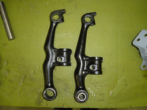
**********
Thanks a bunch. I'm trying to trace ownership. (1962 Vette). I
believe there was only 3 owners including myself but am having difficulty. I
was told the warranty was probably best way
Paul
From: Chip Werstein,
SoCal Chapter Advisor:
Paul,
I have never heard anything about warranty records and Chevrolet claims they
don't have build sheets going back that far.The DMV offices in some states
may keep vehicle ownership records from day one. I live in California which
is not a state that keeps old records. I've owned my 62 since 1973 , a black
plate California car, and I've never been able to trace ownership back
prior to 1973. However, NCRS has shipping records on most Corvettes from mid
1962 going forward. This info can be purchased from NCRS and will provide
you with the build date, ship date and the dealer it was shipped to. The
last I heard they had info on 62's beginning with aprox VIN 6000. Perhaps
the delivering dealer is still in business and may be able to provide some
info. It's a long shot but..........
Chip Werstein
**********
I own a 1962 Corvette which I did a frame off restoration in 1977-80. The car
has been driven 8500 miles since them. During some service this winter, I
noticed play in the left front king pin. There is i n/out
movement of the bottom of the tire. The wheel bearings have no runout. I dismantled
the left side, cleaned everything and nothing looks worn. Measuring everything
with micrometers, I see no difference in pin or bushing diameters compared to
a new set. There IS a .002" difference between the bushing outside
diameter and the inside diameter of the spindle bores. These are the free
floating bushings. This seems excessive and could be the source of the
movement. My question is, Are there any specifications for the good/discard
diameters of the knuckle and spindle where the king pin bushings go? I did not
notice this during the rebuild and can only guess what may have caused these
bores to be large if in fact they are. I really don't want to take the right
side apart to compare sizes, hence the reach-out to you.
Sizes Measured:
Bushing ID - .868/.869" Bushing OD - 1.054" (lower bushing checks
1.053/1.054")
King Pin Diameter .866"
Spindle Bushing ID - Upper bore. - 1.056/1.057" Lower bore 1.056"
My mics are three place, and I plan to repeat the checks with a 4 place mic,
but I doubt tenths of thousands are the problem.
Thank you for your time
Gary
From: Bill Huffman,
Michigan Chapter President:
Gary,
Before you tear your car's front suspension apart, king pins are most likely
only a small contributor to the looseness, especially if only the left side
exhibits this.
Worn tie rod ends, a worn or poorly adjusted steering box worm & shaft
gear,
a worn pitman arm ball stud, worn or poorly adjusted drag link bearing ends,
a worn/loose third arm bearing or even a cracked/broken third arm bracket
(from lifting the front end with a jack) all have an impact on LF wheel in/out
looseness.
I found all but the cracked third arm bracket after I added tapered bearings
to my 1960.
Good luck with your search,
Bill Huffman, Pres.
Michigan Chapter SACC
From: Verle Randolph, Red
River Chapter VP: Bushing Diameter:
1.05"
Bushing Length: 1.315"
Bearing Thickness: .59"
Pin Diameter: .866"
Material Type: Steel
Apply a light coat of grease to the new bushings and insert into the spindle, aligning
the grease channel
on the O.D. of the bushing with the grease zerk hole in the spindle.
IMPORTANT! Installing bushings incorrectly will cause premature wear of
kingpin and bushings.
Verle
**********
have the frame on my 56' cleaned/primed now, what color is
closest to the original frame color bearing in mind i will buy
paint at ace thks gene
From:
Brad Bean, SACC President:
Understand your desire to get the painting done while we are still under a
"stay at home" order due to COVID-19, and Ace has some good products
for around the house, including "Rust-oleum" paints for metal.
However, the frame is the base for everything else that follows, so I'd allow
the time and expense to do it right, including purchasing the proper paint.
Not just color (which is a satin black), but quality, as well.
There are a number of sources for the proper automotive paint, including your
local automotive paint supply stores. If your local stores are closed,
my mail order supply house of choice, for restoration automotive paints is
"Eastwood" of Pottstown, PA. You can call and speak with a
specialist about your specific needs, ie: color, type and quantity. They
also offer spray cans, if you don't have a paint gun and compressor.
Call: I-800-345-1178 or order on-line
www.eastwood.com
Good luck!
**********
Looking to find correct positioning of trunk and deck lid weatherstrip on a
1958 Corvette. Been looking for hours but nothing concrete is showing. Thank You
Dale
From:
Verle Randolph, Red River chapter VP: First, adjust the trunk lid to a
good fit with the body.
The trunk weather strip was installed to trunk lid inner lip with the seam
(ends) located at the bottom center, near the latch mechanism. 56-57 Technical
Information Manual.
From personal experience on my 57, if you actually want it to seal you may have
to custom fit. That is, verify the weather strip is actually in "good
contact" all the way around.
I had to add material to "make the weather strip thicker" on a lower
corner. The material I added was a piece of weather strip with the thick edge
trimmed off. You would get judging deductions for that. I wanted a good seal
because we drive the car.
I suggest you buy the NCRS technical manual for your car. It has lots of details
like this.
Verle
From:
Joe LeMay, SoCal Chapter Advisor:
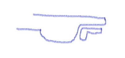
Here is additional information for the trunk weatherstripping.
It is not tubular in shape.
From the 1956-7 JM:
Trunk lid weatherstripping is of the same type as door seal.
It was installed to trunk panel inner lip with the seam located at the
bottom center, adjacent to latch mechanism. Yellow adhesive was brush
applied and may have been excessive. Weatherstripping should not show
signs of paint overspray.
If you have the typically weatherstripping, it is somewhat like an L.
The 'thin' leg is glued to the trunk vertical surface. The fatter leg
lies against the trunk horizontal surface.
Joe
**********
how many body bolt downs (body to frame) are there
-Sharon
From:
Chip Westein, SoCal Chapter Advisor:
The answer is 12. 13
if you count the spare tire hold down bolt.
Chip Werstein
From:
Verle Randolph, Red River Chapter VP: According to the GM
Manual: 1953-1962 Corvette Servicing Guide page 1-47:
The underbody attaches to the frame body mounting brackets at
ten locations (fig.103).
The ten body bolts and washers are installed from the top
side of the underbody.
Verle
**********
I have purchased a 1962 radiator .it has a date
code of 62L stamped on top as usual.but this date goes beyond when they
stopped making 62 cars.the code L is for november. i wonder if harrison made
more than GM ordered or just made extras as the 63s were different.maybe gm
had ordered more as they knew some would get damaged in collisions etc. i am
wodering if anybody has run into this late date code and what it means.i
submitted a ? earlier about what posi fluid to use in my covette and really
apreciate the response.
steve
From:
Verle Randolph, Red River Chapter VP: Aluminum radiator
#31150916 was used in late 61, and all 62 with external supply tank 3151016.
The radiator was probably produced for some time after 62 assembly was ended
for the parts supply system.
The later dates are considered replacement parts. There would be a minor
deduction in judging if everything else was correct (part number,
configuration, etc).
A lot of OEM/NOS parts fall into this category. Everything is correct except
the date code.
Verle
**********
I have been spending time getting our 1961 Corvette
roadworthy again. I ended up taking the tach and speedometer out of the
car and having a rebuild of them from D&M Restoration in Greenville, SC.
Very happy with their work.
The issue I have now is that the tach is not reading
correctly and is reading high through all revs. My question is about the
pulley on the generator. I have a 3 5/8” diameter pulley on the
generator. I am thinking that the 4” pulley would bring the RPM’s down
and make the reading more accurate.
Am I on the right track here?
Rob
From: Verle Randolph, Red
River Chapter VP: The mechanical tachs are similar to the
speedometer, they can be calibrated internally.
You might talk to D&M about it.
When I had my tach rebuilt I talked to them about calibration and they verified
it.
How do you know the tach is not reading correctly? Have you
compared it to another (electric) tach?
I would try to verify the tach reading before doing anything.
Changing the pulley size would adversely effect the generator output.
Verle
**********
I have a 1960 corvette that I am repainting. As part of this effort I need to
repaint the underside of the hood. I will be using a satin black paint; is
this the correct hue? Also are the male hood plates (on the hood) satin black
or are they some type of plating? I have searched the web and found pictures
of both painted satin black and what appears to be silver painted. Thanks in
advance.
Thanks for your time.
Regards,
Book
From:
Bill Huffman, Michigan Chapter:
Book,
Two members of Michigan Chapter actually worked as engineers on the C-1
production line in St Louis.
I asked them this same question several years ago.
The answers are: the inside of the hood was painted in semi-gloss black, on
the production line from inside the engine compartment before the chassis/
body joining. The cowl side edge & two outer edges were masked with
a fabricated drop on & off cardboard mask to keep the outer edges body
color.
Both sets of zinc dichromate plated hood latches (male & female) were
installed in the car before painting the engine compartment. Original
condition would appear to have black overspray on the latch edges only &
not under the latches.
Good luck with your project,
Bill Huffman, Pres.
Michigan Chapter SACC
From: Chip Werstein,
SoCal Chapter Advisor:
Book,
I will once again strongly suggest that anyone wishing to restore a Corvette
correctly purchase an NCRS judging manual specific to their year car.
1. Under side of hood paint. Semi flat black, matching engine
compartment blackout.
2. Hood hinges, latches and locks. These items were cad plated and
installed prior to body painting and engine compartment blackout painting.
They may and probably will appear with blackout paint over spray in varying
degrees.
Chip Werstein
From:
Brad Bean, SACC President:
I agree with Bill's statement that painting the underside of your hood
"satin" black, as well as painting the "male" hood latches
the same color is correct. The latches were affixed to the underside of the hood
prior to painting.
On a personal note... during the first restoration of my '60 Corvette, I
removed my hood latches and noticed the area under the latches was unpainted
fiberglass, supporting the fact the underside was painted with latches in
place.
Over years, paint adheared to the fiberglass, but started pealing from the
bare steel latches. This gave rise to the incorrect theory the latches
had been unpainted. This and personal preference is why you see some
latches in natural steel. However, if restoring as original, this is
incorrect.
Good luck with your restoration!
From:
Joe LeMay, SoCal Chapter Advisor:
Here is additional information from the 1956-7 JM. I do not have a
later C1 JM.
Underside of hood panel is semi-flat black, matching engine compartment
black-out.
All metal items in rear latched & hood lock are cadmium plated,
except for the coil springs, which are painted gloss
black. However, these hardware items were installed prior to exterior
body paint and engine
compartment blackout painting, and therefore may appear with paint
overspray, in varying degrees, much
of which may not have completely adhered to these lubricated parts.
**********
Again thanks for your help.
I did the following tests. Battery is good/Strong/new
Tank is full.
With the key on I have 12.5 volts.
the key on and the 2 lines to the sending unit. the gauge reads full
or full plus.
I removed the sending unit and only get about a .02 change in the resistance from
0.00 to 0.02.
The unit is new (less than a year) but I am I correct to think the sending
unit is bad?
When everything is hooked up, the gauge moves from below empty to empty.
Thanks for you help.
Todd
From: Verle Randolph,
Red River Chapter VP and Advisor: Todd,
Since you have the sending unit out take a close look at the coils. Most
covers are attached by tabs that bend over to hold it in place. Straighten
the tabs carefully, remove the cover and inspect the surface where the
moving contact rubs on the coils. Look for corrosion and/or broken wires. I
have had mixed success with repairing those things. If there is corrosion
you can try sanding with fine emery cloth or sand paper. Don't rub too hard
you can displace wires.
Verle
**********
I just received my dads 1960 corvette that has been parked for 15 years.
I’ve got it running and the fuel gauge doesn’t work. He
says it worked when he parked it. And we replaced the fuel tank
and pick up unit this winter. Mow the gauge doesn’t work.
I plan in taking the pick up unit out and testing it with a volt meter to
ensure it is working.
Any Advise on what to test or look for on the gauge side?
The other question I have is I would like to put larger wheels or tires on
it. Does anyone know the max size that will fit and look
appropriate.
This will be a driver, as it doesn’t have matching numbers.
Thanks for your help. Todd
From: Verle Randolph, Red River Chapter VP and Advisor: Todd,
Since you have the sending unit out take a close look at the coils. Most
covers are attached by tabs that bend over to hold it in place. Straighten the
tabs carefully, remove the cover and inspect the surface where the moving
contact rubs on the coils. Look for corrosion and/or broken wires. I have had
mixed success with repairing those things. If there is corrosion you can try
sanding with fine emery cloth or sand paper. Don't rub too hard you can
displace wires.
Verle
From: Verle Randolph, Red
River Chapter VP and Advisor: Does the gauge not
move at all? Is there fuel in the tank?
The gauge is hot all the time. It should have 12 V. Check that first.
The "sending unit" is just a variable ground.
Check for 12 V to the sending unit. If the key is on and the battery is good
there should be 12 V. If not 12 V, check the wire for damage. Make sure the
connection on the Gauge is clean.
Ground the wire where it connects to the sending unit. The gauge should show
empty.
The tank must have a good ground to the frame or some other place that is
grounded to the battery.
Are you talking about larger diameter wheels or just wider wheels.
I have 15X7 with 215 70 15s. They look good and work good, don't rub. 57
Corvette.
I have no experience with wheels larger than 15"
Verle
**********
My question is
about what fluid I should use in the rear end of my 1961 Corvette. It is a posi
rear. Right now I have an open rear end, but originally my car was equipped with
a posi rear end as it has the vent. I purchased an original correct posi unit
for my car. Which I will be installing this spring. I know I can't use silicone
fluid in the rear end. Would I use 80/90 lube? What posi additive should I use?
Thanks for the help!
If you have any questions email me and I while respond.
Thanks,
Steve
From:
Chip Werstein, SoCal Chapter Advisor:
Steve
I have used in my early Corvette rear ends Stay Lube 80W90 limited slip gear
oil part# SL 2473 ( one gallon with pump) and one bottle ( 4 oz.) of AC Delco
limited slip additive # 88900330......$9.00 from Summit. Put the additive in
first and then fill up with oil.
Chip Werstein
**********
my 1961 (driver) is an early vin with a copper/brass radiator. (Not the
radiator that has the funny offset tank) The fan shroud lacks a good 1 1\2
inches of sealing off the top tank. Is there a special shroud for a 61
that does not have the aluminum radiator?
From:
Chip Werstein, SoCal Chapter Advisor:
I would suggest you refer to the NCRS 61-62 judging manual for complete
information.
Very early 61 base motor cars used left over 60 copper radiators. supposedly
there were 192 left over.
after that all engines used left over top tank aluminum radiators.
After 61 aprox vin 1700 all remaining 61 and 62's used the later
aluminum x flow style.
All 61 and 62 fan shrouds are the same
However there were 3 different core supports used in 61 so you may have a
radiator/core support mismatch.
I will also add that in 50 years of playing around with C-1 Corvettes, I have
never seen a 61 with an original copper radiator.
Chip Werstein
From: Verle Randolph, Red
River Chapter VP and Advisor:
The shroud should be a three piece top. The center
shows to be 4 inches depth.
Logo is P in a keystone. Stamp on the vertical.
No measurement on the gap or set back on the fan. All
shrouds are the same but supports are different.
Verle
**********
Found a 59 Vette n trying to verify vin to engine....is there anyone or a
document to do that? Also original specs ? Color etc.
From:
Brad Bean, SACC President:
Sorry, but on C1 Corvettes, there is no direct link between the VIN and the
engine number, and there are no longer production records indicating which
engine was installed in a particular vehicle (all records were destroyed in a
fire). However, to see if the engine is "possibly" the original
block, you can estimate the vehicle's date of production by using the VIN and
Corvette monthly unit production numbers; then compare that with the production
date of the engine block (located on the engine's stamp pad) to determine if
they are compatible. There are various opinions on this but general
guidelines indicate the engine block should have been produced two to six weeks
prior to the vehicle's production date. If the these align, it indicates
the numbers are "matching", but not necessarily "original".
As mentioned all C1 production records were lost in a fire, and C1s did not
have trim tags or build sheets, so unless the previous owners kept the
original bill of sale or early items (like color photos and copies of vehicle
registrations, etc...), color and options are difficult to substantiate.
There are some physical traits on the vehicle that could indicate if it came
with certain options, but you either need to know what you are looking for or
know someone who does and is willing to help. A local NCRS C1 judge or
restoration shop, specializing in early Corvettes, might be your best bet.
The stamp pad on a 1959 283 CI block is located on the front right
(passenger) side of the block, just beneath where the valve cover meets the
manifold. It protrudes out from the block and the numbers can easily be
seen with a flashlight with the hood open.
The engine number should be stamped into this "flange" (not raised
numbers/letters). It should be six characters long. Starting with the
letter "F". All letters are capital.
Starting with 1960 production the last six numbers of the VIN will precede
the engine number. So you can tie in the serial number with the
engine, but not for '59.
There are two ways to determine original color, but neither are an option if
you don't own the vehicle. In most cases, the color name was written on
the back side of the passenger compartment (inside of the trunk) with a greece
pencil. If you remove the cardboard front trunk liner, you can sometimes
see the outline of this thru the paint. If the car has been restored and
repainted, this is probably gone. The other way is to scratch off paint
from one of several areas, where it would be difficult for a shop to
have removed all of the original paint before repainting (such as the inside
corners of the gas filler compartment). But I doubt the current owner
would consent to this and even if they did it is not 100% conclusive, as if
the restorer had the body dipped, all traces of the original paint are
probably gone.
I'm guessing you are looking to purchase this '59 and would like to verify
some things before you buy it and time is short. If so, my advice would
be to enlist the services of a local professional. If you have the time
and are in this for the long run, suggest you locate a copy of Noland Adams'
book: "The Complete Corvette Restoration & Technical Guide - Vol.1
1953 Through 1962". These have been out of print for decades, are
scarce and pricey (if you can find one), but a good investment and will help
you understand the physical "tell - tell signs" of what to look for,
what information is out there and where you can find it.
Good luck!
**********
Howdy, this is Darrell 1959 C1
I am looking for some guidance to the right
direction to get the interior done my 59. It has been a complete body off
restoration and I am not sure where to start with ordering interior kits,
supplies and such. I will need foam for seats, carpet, and anything else needed
for a 59.
Can anyone give me a direction or where is the
best place to get interion supplies?
From:
Brad Bean, SACC president:
Appreciating the need not to give endorsecements, one can't answer this question
without sharing the benefit of our experiences, including brands. Also,
there are as many answers to this question as there are members on the
panel. Frankly, it depends on what Darrell wants to do with his C1 and
what he wants to spend, with the most accurate and correct reproductions
generally being the most costly.
That being said, Al Knoch is generally recognized as one of the best for
accuracy and quality (& most expensive). However, decent quality
interiors are available from Paragon, Corvette Central and Corvette
America. One more note... if he wants the original looks but the comfort
and feel of leather, Corvette America also makes a leather alternative
interior.
Of course, the end product will only be as good as the quality of the
installation, so choose your upholstery installer wisely. Also, if you
are going to pay the price of a new interior, I recommend going the extra
distance and purchase new springs and padding, as well.
Leather was not offered on C1s, including 1959. I mentioned leather only
as an alternative, as I wanted the look of the original interior, but was more
interested in comfort versus having the car judged at NCRS. And... living
in Florida, didn't like sticking to the vinyl seats in short pants during the
summer's heat.
Again your end purpose should govern the type and quality of interior you
choose. If restoring to NCRS & Bloomington Gold standards, then
you want the most correct and best quality interior; Al Knock would be a
good choice. However, if you want a correct looking
"driver", the others will work without the additional expense.
**********
Electrical issues: I have a 62 Vette which I have done my best to keep
as original as possible inside and out. I was wanting to change out the
radio system to a more updated unit with XM services. Thus, I had the
ignition switch on during a period for hookup but when I attempted to start
the car it wouldn’t start. After checking under the hood for a short period
I touched the coil in checking the coil wire and it was hotter than fire.
I noticed after close inspection it had cracked. (I take it the points were
closed). Changed it out, removed distributor cap and points and they also were
fried. Changed points and condenser and properly set points with feeler gages.
Turned ignition and car started right up. Checked gauges battery was on
full charge all working. Went to turn off engine after battery
changed up and engine continues to run like I had not turned ignition off but
left it on. I had to pull coil wire to turn off engine. Went to
troubleshooting. Disconnected the hot wire to the radio. Thought it may
be my ignition switch. Changed it out started engine, turn switch to off
engine still running. Changed my voltage regulator and ballast resister
no luck. Engine continues to run on off. I am lost. Any HELP!!!
From:
Joe LeMay, SoCal Chapter Advisor:
Hi Darrell
You may have an ignition switch issue. When the switch is off, there
should be no voltage to either the start wire or the run wire that goes from
the switch to either side of the ballast resistor. When the switch is at
start, voltage goes to the ballast resistor and directly to the coil.
When the switch is ON, voltage goes to the ballast resistor, through the
resistor and to the coil.
Also start the car while checking the voltage at the coil.
1. Turn to ON. Voltage should be less
than 12V (8-11V?)
2. Turn to start. It should be 12-14V during
starting.
3. Start the engine, and release the key.
The voltage should drop to less than 12V (8-11V?) while running, since the
electricity should flow through the resistor. If the voltage does not
decrease, it is pointing to an issue with the switch.
Check these. You may have shorted the switch.
Joe
**********
I am having some steering tightness in the 61 Corvette. I Put new grease
sockets and greased, but still hard to turn. Have you had any of this before?
Maybe needs steering fluid!
Roger
From:
Chip Werstein, SoCal Chapter Advisor:
Roger,
This problem is nearly impossible to diagnose with your 3 sentence
explanation, but I'll attempt to give some possibilities as to the root of
your problem.......in no particular order.
1. There are 20 grease fittings in the front suspension. Did you grease all
of them?
2. Do you run big tires or stock 6.70x15? Wider tires will make the car
steer harder.
3. Do you have the stock 17" steering wheel or a smaller one? The big
wheel gives the driver more leverage.
4. Has the front end ever been rebuilt? If not, after nearly 60 years it is
probably worn out.
5. Have you checked the steering box for lubricant? Manual calls for 90
weight gear oil, but it will leak out quickly. I use 680 weight gear oil and
I still have small leaks. Many people use grease but I don't like it.
6. Steering box could be out of adjustment.
7. Steering box may be worn out especially if it has been running dry for a
while.
Sorry I can't be more specific.
Chip Werstein
**********
I have two questions,
I have 1961 Corvette that oil canister that holds the filter is leaking around
the bolt that holds the filter to engine.
Rear end drain plug is also dripping oil after I installed new seal.
From:
Chip Werstein, SoCal Chapter Advisor:
Glenn,
I am not aware of any company that offers a rebuild kit for the oil canister.
Try to tighten the bolt as much as you can.....that might stop the leak. Other
options are replace the canister with another either used or repo. Or you
could convert it to a spin on style filter.
Rear end drain plug leak. I always put a good thread sealer on the drain
plug. You will need to drain the rear end, thoroughly clean the plug and
housing threads, re install the plug with thread sealer and refill the rear
end.. I use a product called Right Stuff.
Chip Werstein
**********
Does anyone know what the function of the micro switch near the chock cam is
for. The only way I can keep my car running after starting it is to insert a
piece of cardboard between the switch and the cam. If I do not insert the
cardboard the car barely runs and appears to run very rich.
Thank You,
From:
Larry Pearson, SoCal Chapter Advisor: Craig: The early FI units
(prior to 1958) had an electric solenoid attached to an arm that, when activated
by the car's starter circuit, caused full enrichment from the spill valve to
assist in starting the car. The solenoid is only activated while the
starter is cranking. When the starter is released by the ignition key the
solenoid is disabled and the FI unit operates in the normal mode without
starting enrichment. The purpose of the micro switch is to disable the
solenoid during engine cranking if the engine is flooded by flooring the gas
pedal as you would with a carburetor. This is process is called
"unloading". Evidently your unit is mis-wired so that the
starting solenoid is always activated when the car is running or starting,
causing a very rich situation when the car is running. That is why you are
having to activate the micro switch with a piece of cardboard to disable the
solenoid. You need to correct your wiring error by connecting the FI unit
starting solenoid to the starter solenoid circuit and not the car's 12 volt
battery.
Starting in 1958, a device called the Cranking Signal Valve (CSV) was
introduced and the expensive solenoid and micro switch were eliminated.
Initially,the CSV was mounted directly to the Plenum and it caused full
manifold vacuum to be applied directly to the main diaphragm on the fuel meter
to cause the needed enrichment during starting. In later units the CSV
was moved to the Enrichment Diaphragm Cover causing manifold vacuum to be
applied to the enrichment diaphragm assembly and that caused fuel enrichment
during starting. When the engine starts, manifold vacuum increases and
the CSV senses this and shuts off the flow of manifold vacuum to the main
diaphragm or the enrichment diaphragm. To achieve "unloading"
when the engine is flooded, flooring the gas pedal causes the air meter
throttle valve to fully open, reducing the manifold vacuum to the CSV and
reduces starting enrichment. When the CRV fails to shut off the manifold
vacuum when the engine starts, the engine runs in a very rich mode like you
are experiencing. When this happens, the CRV is defective and has to be
replaced.
Larry Pearson
**********
I’m looking for a template or dimensions to position the flags and “fuel
Injection" insignia (coves and trunk lid) on my 1957 Corvette. Do you
know where I can find that information? The mounting holes were eliminated
when the car body was restored. Thanks!
>
> Bill
From:
Bill Huffman, Michigan Chapter President: Bill,
Before you start drilling new holes, clean the back side of the cove panels down
to the clean fiberglass. If it was really a fuelie, the holes filled with bondo
are most likely still there.
Re-drill from the back side using as small a drill bit as possible then clean
out the original hole with a slightly larger drill bit or small round file from
outside the car.
Don't punch it out with a hole punch from the inside because that will blow out
a large hole in your paint.
Good luck with your project,
Bill Huffman, Pres.
Michigan Chapter SACC
**********
I just found your website and have an issue with my 62 Corvette. I
purchased the car in 1975 and have significantly restored it. I have
not, however, done anything to the transmission. It had a Hurst shifter
installed when I bought it. Lately it tends to 'lock-up' on the 2-3
shift and get 'stuck' in 2nd. Crawling under the car and wiggling the 2
levers from the transmission will usually free it, but I can never tell
which wiggle does the trick. Is this a tranny problem or a Hurst
problem? Any suggestions?
Thanks so much.
--
Fair Winds,
Mark
From:
Chip Werstein, SoCal Chapter Advisor:
Mark,
I will assume your car has a 4 speed. I believe in always trying the
"simple fixes" first. Before tearing into the transmission, I would
re adjust the shifter. It's quite simple, but it's a tight working space in
the trans tunnel. Hurst shifters are almost indestructible. It is possible the
your 2nd or 3rd gear levers have somehow become miss adjusted or the 3rd gear
stop has become loose and moved. Google Hurst Competition 4 speed
adjustment for directions. Hope this solves your problem.
Chip Werstein
**********
Solid Axle Corvette Club:
Trying to find correct or original screws to mount speedo to dash set of two.
For a 1956 Corvette.
Thank you
Richard
From:
Joe LeMay, SoCal Chapter Advisor:
The assembly manual (section 12 sheet 11) shows the speedometer is mounted
to the dash with two PN 187572 screws that bolt to nut plates that are
riveted to the dash. A have a note that says they are recessed hex
head machine screws.
Joe
**********
Dear Solid Axle Club,
I have a 1957 Corvette with an original Rochester Fuel injection. I bought car
In 1995 after a frame off restoration started in 1991.
The fuel injection was restored in that time frame. It basically has been
running great since. Last week I noticed a strong gas smell
and noticed a lot of gas pooled on intake manifold. I cleaned up and haven't
started since. Does this sound like a unit leak?
I'm taking it to my local rod mechanic Monday
just to make sure it's not coming from somewhere else.
Can you recommend someone located near me who can repair or rebuild unit if
necessary. I'm located in Temecula Valley.
I'm not a member but know several of your members especially Walden Dahl who has
done lots of work on this car. I'm waiting
a return call from him. Also if you know any tech sites that might explain
problem.
Thank You
Ron
From:
Larry Pearson, SoCal Chapter Advisor:
Ron: If the fuel leak is under the fuel meter, the likely problem is the
spill valve cover under the fuel meter. It uses a rubber "O"
ring to seal it, and these have a tendency to crack and leak when they get
old. If this is the problem, do not drive the car!!! There
is high pressure fuel under the cover, and this leak is the leading cause of
FI equipped Corvettes burning to the ground. You have to pull the unit
to get at the cover screws, and you will need a new O ring. It is easy
to install.
Larry Pearson
From: Chip Werstein,
SoCal Chapter Advisor:
Ron,
My guess is that the gasket between the high pressure pump and the fuel meter
has failed or the high pressure shaft pump seal has failed. They are fairly
simple fixes but the FI unit will need to be removed. Regardless do not drive
the car. It is a fire looking to start. There are two people in your area who
are fuel injection experts. Chuck Smith in Valley Center and Doug Prince (
818-425-0679) in Murreitta. Walden is also a good choice but somewhat
inconvenient for you.
Chip Werstein
**********
I have a 56 corvette and the speedo bezel needs to be restored/replaced. My
question is are the groves on the front of the fuel suppose to be
painted black or left chrome?
From:
Joe LeMay, SoCal Chapter Advisor:
Below the speedometer, the recesses are painted black.
From the Judging Manual, "Circular grooves in bezel have black paint
strips."
Joe
**********
Hi Guys, you been a great help in the past
and I’m hoping you can give me assistance with my sun
visors?
I purchased a new set of sun
visors from Corvette America. The sun
visors have a seam around the entire perimeter where the vinyl meets.
There are no predetermined holes for the mounting rods which must go into the sun
visor. When I called Corvette America for technical help they had no
answer and suggested I ask a form. Can you please help me in how to best
create the hole in the sun
visor to insert the rod?
Thanks again for your help,
RS
From:
Bill Huffman, Michigan Chapter President:
Roger,
The
assumption by the aftermarket manufacturer & vendors is that you have
existing sun
visors that you use as a model for fitting your new hardware kit into your new sun
visors. They fit exactly the same way.
I would use a blind hole locator punch from my screwdriver set to locate
the holes in the visor inner structure & penetrate the vinyl.
I'm
certain that Paragon https://www.paragoncorvette.com/ would
be more than happy to fit new hardware to your visors if you or a local
shop are unable to handle it.
Good luck with your project,
Bill Huffman, Pres.
Michigan Chapter SACC
**********
Hello,
I have 61 Corvette, my question is that
my rear license plate does not work. I have power to the socket and the bulb is
good.
I have notice that there is no ground to the light. Do I need a ground ? If so
how do I wire it. I have looked for diagram on the internet no luck.
Regards,
Glenn
From:
Bill Huffman, Michigan Chapter President:
Glenn,
The
license plate light is grounded using the same wiring harness as the rear stop
lights.
Check
out page 66 of Paragon's C-1 catalog for a picture. https://www.paragoncorvette.com
Bill
Huffman, Pres.
Michigan
Chapter SACC
there
is no wire coming out of the harness, I need to run ground wire from the light
to ?
I
have power at the socket
(From
Bill Huffman) All Corvette electrical
equipment (lights, gauges,tank sending unit, radio, battery, WS wiper,
etc.) are grounded to the frame / chassis.
Somehow the ground lead has broken or been cut. So open the rear light harness
cable covering (tape), find the ground wire (use a meter to verify continuity to
the chassis), splice in an extension wire and connect the ground to the lamp
housing. Consult your local Advance Auto Parts or Auto Zone for help.
Or
buy a new rear light wiring harness (Corvette Central P/N 661325).
Or
buy a new rear light wiring harness (Paragon P/N 5319).
BTW-
Get yourself a 1961 Corvette assembly manual CC or Paragon or Mid-America.
It
answers most, if not all, your questions about your '61.
Good
luck,
Bill
Huffman
**********
Hello Everyone
I purchased a 61 fulie 35 years ago . Its been running , is there a way to
track the serial #
Thanks
Jim
From:
Brad Bean, SACC President:
This is stating the obvious, but it may be your only opportunity, because there
are no factory records at Chevrolet or GM on C1 Corvettes as hard copies were
destroyed by fire, years ago.
If you kept a copy of the title from your original purchase, this would give
the name and address of the previous owner, and that's a good start. If so,
you can write them to see if they have information on how long they owned the
car and if they retained any records on the car's previous owner(s). But,
be prepared for a dead end as I've owned my C1 for 26 years, and when I wrote
the former owner listed on the title from my purchase, I found they had long
since moved with no forwarding address.
Another possibility, if you've stayed in the same state since your purchase
and it has a history in the same state, there is a small chance your state
department of motor vehicles may be willing and able to help track it. However,
most state records only go back so far and hard copies were destroyed when
they converted to microfilm and these were discarded when they converted to
digital.
A long shot... SACC members have the ability to place a free ad our
quarterly magazine, "On Solid Ground". Place an inquiry ad
asking if anyone has information relating to your VIN number, along with your
contact information, and see if anyone responds.
These are my only ideas. If another of our members has any suggestions,
I welcome their comments. Good luck!
**********
Good morning:
Would we have a diagram of wiring generator/regulator and distributor with tach
drive gen on 1961 corvette?
Harold
From:
Larry Pearson, SoCal Chapter Advisor:
Harold: Most of the answers you need and much more are found in
Chevrolet's official shop manual for the C1 Corvettes: Corvette
Servicing Guide, Publication ST-12. The Chassis Wiring for 1961-62
models is found on page 12-14. The actual servicing of the distributor
is found in Section 6Y, Engine Electrical. ST-12 does not cover the
servicing of the generator and voltage regulator and the operation of the
car's charging system. For that you have to refer to the 1961 Chevrolet
Passenger Car Shop Manual, Publication S&M-32, Section 9, Electrical
Systems.
Corvette Central sells the ST-12 Corvette Servicing Guide reprint, but not the
car shop manual. Actually, any Chevrolet car shop manual for the
1955-1962 models should give you the information you need to service the
charging system. If you will be in Los Angeles on Saturday,
November
9th, I will be teaching the operation and servicing of the C1 Corvette
electrical system at our SOCALSACC Fall Tech Session.
Larry Pearson
**********
Greetings!
I’ve recently installed a power rack and pinion steering system in my ’62
Corvette. I removed the serial number tag from the original column after taking
a picture of it in position. I contacted our county’s Ohio State Highway
Patrol office, and the Sgt there is willing to work with me on properly
documenting the repositioning of the s/n tag to the driver’s door post.
I’m curious if you have any photos of 1959 and earlier C1s with the tag
location on the door post, so I can duplicate the position as closely as
possible. The local Sgt actually suggested positioning the tag on the door post,
as opposed to the cowl near the steering column, saying he has seen many early
Corvettes with them there. He was not aware of the ’62 tag being located on
the column.
Once I have a photo of a door post-mounted tag, I need to take the car to the
local Post, where they will write me a letter explaining why the tag is not in
its original position. Ant help will be appreciated.
Regards,
Dave
From:
Joe LeMay, Socal Chapter Advisor: This is an NCRS article that relates to
California, but should be a good guide for use in any state.
VIN Verification
Joe LeMay (55193)
(Although the process applies to any car, it was
specifically for my 1957)
There are some words and phrases that we in NCRS really
like. They are things like: typical,
appears to be factory applied materials, casting date within 6 months of
production date, Top Flight, Duntov.
There are other words and phrases that we in NCRS do not
like. Not typical, wrong, incorrect,
“not lacquer,” and the worst one- counterfeit.
Counterfeit can really get you in trouble.
You so proudly show up with your car for a judging meet for
flight judging, sportsman, or just to be there.
Someone looked at your VIN tag with an opinion “this is not the VIN tag
that was issued and installed at the factory.
St. Louis did not use that one.” You
are informed that your VIN tag is not the typical factory VIN tag.
It is a counterfeit.
The part of
the Judging Reference Manual that applies to the VIN tag reads:
“The
car must have the correct attached Chevrolet factory Vehicle Identification
Number (VIN) plate or an attached valid state-approved replacement ID plate that
matches title and/or registration. …..
Any car appearing without identification as described shall be ineligible for
any NCRS judging.”
So what needs to happen now?
It is really simple. There
are two options.
1. Just show your car with a bad VIN tag to the California Highway Patrol.
They will look at it. Then
they take your car away and you never get it back.
That is it. Never to be seen
again. Only the pictures remain.
Judged again? You just want
to drive it again!
2. Keep the car. Send a letter to
the NCRS. Tell them they will never
see your car again. You are through.
No those are the wrong approaches.
You have a VIN tag that looks like this (photo).
Looks good, right? It is the
tag that came with the car, right? You
bought it that way. You have a CA
title. The registration is current
and you legitimately drive the car on the street.
The process with this counterfeit mess is much simpler and
you will not lose your car. The
resolution is clearly stated in the JRM. You
need to get your VIN verified with a state-approved replacement ID plate.
The process can sound scary. The
reality is something different. Here
is what you do in California.
During the assembly process in the St. Louis plant, the VIN
number was stamped on the frame. On
a C1, the VIN number is stamped twice on the frame.
The frame stamps are on the top side of the frame right below the driver
seat, about half way along the door. Then
during body drop, the corresponding VIN tag was attached to the body.
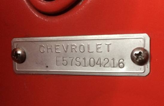
Although there is a VIN tag attached to the body, the true
VIN number for the car is associated with the number stamped on the frame.
During restoration or collision repair, if the body or frame is changed,
the VIN tag that matches the frame stamp is to be used.
If the body is replaced, the VIN tag that matches the frame
must be installed on the replacement body. Nothing
changes. If however the frame is
replaced, the VIN tag that matches that frame must be used.
Your VIN has changed. You
need a clean title for that replacement frame to be installed.
Your car will now have a new VIN, new title, and new registration.
You will not be able to see the VIN on the frame with the
body firmly bolted to the frame. How
do you see the frame stamp and get a photo of the frame stamp?
You may need this information if you want to be certain this old car that
changed hands so often is what your paperwork says it is.
Here is the process to see the frame stamp and get a photo
of it. Unloosen all the nuts for the
body bolts a few turns. There are
two at the radiator support, four on each side under the body (8 total), and the
two in the rear in the fender wells. Now,
remove the four nuts under the body on the left side.
Place a 2x4 wooden block on the body floor just outboard the frame.
This is where the outer seat bolts are located.
Ensure the block is long enough to support the weight of the body without
cracking the floor. Jack up the body
an inch, creating space between the body and the frame.
The body will move. Just do
not go too far.
Now find the VIN frame stamp.
It should be about in the midpoint of the door.
You may need to clean the top of the frame to remove dirt, etc.
Use a mirror placed and held against the body.
Reflect a light onto the frame. You
should see both VIN stamps. They are
only a couple of inches apart.
Take a few photos of both VINs stamped on the frame.
I taped a mirror to the body to hold it in place.
It could take some experimenting with the angle and intensity of the
light and the camera to be used. The
camera needs to be able to focus very close to the object.
I had more success with an iPhone 5S than a digital camera.
I may not have had a macro setting on the camera?
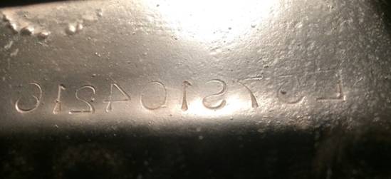
So now what do you need to do?
Gather all the information you may have on the car.
It could be the current title, and any past titles that you have as a
record. You have your registration,
license and insurance card. You have
a photo of your VIN tag, and the photos of the VIN frame stamps.
Make copies of all this information.
You will be submitting the copies. I
did not have any of this information returned to me, so do not provide original
documents. Call your local CHP to
make an appointment to have your VIN verified.
They do this all the time and it is not some crazy request.
You will most likely meet others at the CHP office doing the same thing.
When I was there, a guy had inherited his mother’s car from Georgia, it
had been repaired and the VIN tag was missing.
Go to the CHP office for your scheduled appointment.
They will take all your paperwork, and take your car behind a fenced area
to complete the process. They will
drill two holes for the rivets to attach their replacement ID plate to your door
frame. Their ID plate number will
match the VIN tag and the current title. They
will also provide you with a copy of an Application for Vehicle Assigned
Identification Number Plate. That is
their record of the replacement ID plate.
I requested they not mount their replacement ID plate to
the space where the original VIN tag was located.
They added theirs below the original area.
I did not want to lose the original look of the VIN tag.
A potential new owner may want to see that tag.
The entire process took an hour and was very easy to do.
Here is the final product.
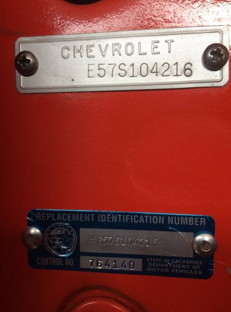
One more thing; If you are going to have your car judged
(which is why I went through this exercise), remove your ‘counterfeit’ VIN
tag before it is presented for judging. NCRS
does not want to see that non-original on the judging field, but the replacement
ID plate meets all of their requirements.
**********
Hello
I have a 1960 corvette I am rebuilding. Have a few issues I have ran into.
The temp gauge reads about 20-30 degree to high can these be recalibrated?
The engine when 1st started when cold has 70 lbs pressure the oil
gauge only goes to 60 will it damage the gauge going to 70 when warm drops
down to correct temp?
Is there someone that rebuilds the original horns?
Thanks
Jeff
From: Joe LeMay:
Hi Jeff
The temp gauge can vary depending on the ambient temp and the condition of
the cooling system. Those variations also consider whether the gauge
itself is reading correctly. What is very important with these systems
is whether the electrical connection between the gauge and the threads is
continuous. If you use Teflon tape or some other material to seal the
sender with the intake manifold, that can create added resistance, and an
inaccurate gauge. You can check the sender by immersing it in a pot
off very hot water at a known temperature. Keep in mind, these engine
temperatures can rise in hot summer months.
Oil pressure as high as you are seeing is very easy to create. Just
get an oil pump with a high pressure spring. The stock oil pressure
for these C1 engines is 45 psi. You can restore that pressure by
selecting and installing the correct oil pressure relief spring. That
will require access to the oil pump. Is that part of your rebuild?
The gauge itself is very simple and usually trouble free.
All
C1s used a 45 psi oil pressure spring and had a 60 psi gauge. A
higher volume pump is not beneficial in a small block. It just allows
more oil to be bypassed at the pump. It also puts more oil into the
top of the engine where it can leak out. The oil pressure
spring that comes with any new pump may not be correct, and I suggest making
the change at the time of installation to insure you will have the correct
and desired pressure, via the spring. The 45 psi spring is available
from GM as P/N 3814903. Order that spring and insure it is installed
in the pump. It will provide 40-45 psi @ 2000 rpm in a hot motor.
There is also the 49 psi green spring that is available through Melling.
There
are a couple of horn rebuilders. We just lost one of the better
rebuilders. Horns are very simple and disassembling one may show how
easy they are to adjust. Are you looking to try it yourself?
Joe
LeMay
**********
Need help! Would like to get information on the alignment and how to DIY
recover the cloth top on my 58 if anyone has DVDs or step by step instructions
I would appreciate it very much there doesn't seem to be anyone in my area that
knows how at a reasonable price so once again I get to do it myself thanks!
From:
Larry Pearson, SoCal Chapter Advisor:
Jerry: Al Knoch not only sells a convertible top for your 1958 Corvette,
but he sells a DVD that instructs you on how to install the top yourself.
He sells his Top Install DVD for the 1956 through 1962 Corvette for $60.
His toll free order line is 1.800.880.8080, or visit his website at
http://www.alknochinteriors.com.
Larry Pearson
**********
Jack
/ Bill,
I
put the Vintage Generator on with all the correct bracket for 61 Corvette. So
far everything is working fine.
How
to make few changes. Mounting plate for the Generator had to slot holes in the
plate that got mounted to the
exhaust
and the correct fan belt would not work. There is no way to get this belt on.
Other than that everything is align.
Have
about two fingers from heater hose to belt. So Far so good. Again thanks for
your help. I have join the Solid Axle Club,
but
they did not cash my check yet.
Two
last question. What color paint is on 61 Corvette firewall and inner fenders ?
Do you know any good transmission shops in New Jersy,
My
T-10 Trans is leaking oil around the shaft that holds the cluster gear
in.
Regards,
Glenn
From: Chip Werstein, SoCal Chapter Advisor:
Glen,
Generator. I am guessing that you have the wrong generator mounting plate
and/or wrong u bracket. There are different parts for different
applications. The belt issue could be incorrect size gen pulley or belt too
short.
Trans leak. If I am understanding you correctly, the trans leak is
where the cluster shaft enters the front of the trans case. Your leak would
be between the front of the trans and the bell housing. Before sending it to
a trans shop, I would try the following simple fix.
1. loosen the 4 bolts that fasten the trans to the bell housing about 3/8
". Do not remove them. With a large screwdriver, pry the trans back
until it contacts the bolt heads.This can be done without removing the drive
shaft or shifter.
2. clean the area between the trans and bell housing. I use the edge of a
rag soaked in lacquer thinner. If you don't mind making a bit of a mess
brake clean will work too.
3. take a linen business card (not a shiny card) or gasket material and
cover both sides in gasket sealer.I use a product called The Right Stuff
available at any auto parts store.
4. insert the card between the trans and bell housing so that it completely
covers the cluster shaft area. Re tighten the 4 trans bolts. Let it cure for
a day. This little trick should solve your leak. If it doesn't you have a
very worn cluster shaft or hole or the leak is elsewhere. Good luck.
Chip Werstein
**********
I
have a 1960 FI and it has windshield washer system. I am in need of a wiring
schematic ( rubber hoses) for the 60Vet.
From:
Bill Huffman, Michigan Chapter President:
Ron,
Page 73 of Paragon Reproductions C-1 catalogue shows the fuel injection
windshield washer set-up. However, it appears to be a smaller copy of a drawing
contained in the GM 1960 Corvette Assembly Manual which is really what you need
to get. It's available from any of your favorite Corvette parts vendors.
Bill Huffman, Michigan Chapter President
**********
I have a 1960 with a reproduction steering
wheel. I need a high quality Red replacement or a place that can repair the
original which has cracked at the spokes.
Can you help?
Tom
From: Bill Huffman,
Michigan Chapter President:
Tom:
If it is top flight or Duntov material, Richard Dunham is your guy. He is an
NCRS Judge & SACC Member from Michigan who restores original steering wheels.
It's not cheap...he offered to upgrade my '60 wheel last year for $1000.
If your car is similar to mine, a really nice driver I've owned for 51 years and
don't plan on selling , Corvette Central or Paragon and a half dozen others
sell quality reproduction wheel kits for less than $500.
Regards,
Bill Huffman, Pres.
Michigan Chapter SACC
**********
Hello,
I have a question about my 1960
roadster. When the convertible roof is folded and the rear deck closed, the fit
is terrible. The rear deck sits about an inch above the rest of the car! I’ve
attempted to adjust the roof with no luck. If you can provide any help with
respect to getting a better fit I’d very much appreciate it.
My apologies for the email
signature…a guy has to work!!
Rog
From: Larry Pearson, SoCal
Chapter Advisor:
Roger: I have never heard of the type of problem you seem to be having. I own
a 60 and two 62's, all with soft tops. You seem to be saying that with the
soft top assembly folded into the top compartment, when you slam the deck lid
and it latches, that the deck lid back surface pops up about one inch above
the trunk lid surface. Does it do this with the soft top up in place? If
not, I suspect that the connection between the soft top cover hinges and the
soft top fiberglass cover is broken, and needs to be repaired.
One of the problems with
today's
service replacement soft top fabric is that it is at least twice as thick as
the original fabric. The result is that the top assembly does not easily fold
down into the top compartment cavity. The ends stick up, and you have to slam
the cover to compress the folded top into the compartment. This puts a lot of
stress on the fiberglass soft top cover, and this could have resulted in the
fiberglass connection with the cast steel hinges has fractured. If this is
what happened, it will be very difficult to repair the fractured fiberglass
well enough so that it will be strong enough to take this kind of force. You
may have to purchase a used top cover. A used cover should be readily
available, but will have to be painted to match the rest of the car.
Another possibility is that the soft top cover hinge assembly has broken
loose from the car body. You will have to remove the cardboard cover in the
trunk to see if this happened. I have never heard of this happening.
Larry Pearson
From:
Brad Bean, SACC President:
I too have a '60 with a soft top. Like you, I had a similar folded roof
problem, to the point that it cracked my deck lid at the two ends.
Unless the car has been altered, the distance between the bottom of the
storage area and the deck lid, when closed, is a constant.
Assuming you have made all possible adjustments... my first
question... do you use a "pillow" or folded towel to keep your rear
window from being scratched? If so, make sure it does not impede with
the joints when folded.
If not, and it's the correct top for your car, the struts are probably
bent. Another sign that is is the problem is the two support bars,
with weather stripping, above the side windows form a slight "V"
rather than being straight across. The bends may not be detected by
the untrained eye, and if you have not done this before I reccomend
sending it to a professional soft top shop to have it straightened.
This process will probably require the replacement of the soft top
material, as well. While it's there, may as well have them refinish
the metal and replace the weatherstriping.
This has been my experience, but if someone else has a less costly
solution, I invite them to please pass it along.
Good luck!
From: Bill Huffman,
Michigan Chapter President:
Rog,
Since you live in area code 705, we will be at Mackinaw Corvette
Crossroads on
August 24th. If you can make it, I'd be happy to take a
look at it.
The deck lid position relative to the body is controlled by the hinge
mechanism and the latch. If tight & properly adjusted, it should be
the same whether the top is up or down.
Either the top is not folding properly (could be long handles on the
top header bar latches or 60 year old top frames don't fold the way
they're supposed to) or the tank cover is sitting too high to allow
the top to fold.
If there is anything under your deck lid other than the folding top
frame, take it out. You can only pack extra stuff after the top is
fully seated.
The few C-1 big tank cars (mostly racing cars with heavy duty
suspension & brakes) made were hard top only due to insufficient
folding top space. Was the folding top added later and not installed
correctly ?
Buy a 1960 Assembly Instruction Manual. Owning a C-1 can be a study in
the history of questionable repairs or modifications by previous
owners. The manual tells you what's supposed to be there.
Good luck with your project,
Bill Huffman, Pres.
Michigan Chapter SACC
**********
Having an intermittent problem with switch to start engine, I have replaced
switch still have problem
Ignition lock cylinder?? Is this next? Replace or is there a repair procedure
to follow
Input appreciated
Thanks
From:
Larry Pearson, SoCal Chapter Advisor:
George: If the replacement ignition switch functions mechanically then
the lock cylinder cannot be the problem. You don't give many details, so
I will go down the list of things that could be the problem.
1. When you turn the switch to "START", does the interior
light (an option in 1958) go out? If your car does not have the interior
light over the radio, then turn the headlights on instead. If the
light(s) goes out, then your battery is defective or the terminals to the
battery are corroded and need to be cleaned.
2. If #1 passes, then does the starter solenoid click when you turn the
switch to START? If not, then the problem is either the wiring to the
starter solenoid or the solenoid itself.
3. If #1 & 2 passes, then the problem is the large contacts inside
the solenoid that connect the battery to the starter, or the starter motor
brushes are worn out.
**********
Driving season is coming soon here in the Northeast. I’d like to
install brighter LED taillights in my ’62.
From: Bill Preston, Red
River Chapter President:
I recommend changing to an LED assembly, not just changing the bulb. The
assemblies are much brighter than the bulbs alone. One source for an
acceptable unit is Corvette Central part #492138. A word of caution: If you're
changing the front parking lights to LED, as well, you will need an LED
flasher or equalizer. If you leave your front parking lights with the original
type incandescent bulbs, you won't have to change the flasher. (The LEDs pull
so much less current that the existing flasher won't function without a fake
load on it)
Bill Preston
**********
Hi Folks !
Love my ’62 but frustrated with
the audibles when rough road causes both doors to rattle. Think I could
repair/replace cause but would appreciate knowing beforehand what parts are
usually at fault and what is required to effect repairs to make it nice and
tight again. Any words, books, articles, videos would be helpful.
Thank-you,
Gary
From:
Larry Pearson, SoCal Chapter Advisor:
Gary: The door windows have a chrome plated steel frame that rides in
felt or velvet channels to avoid a metal-to-metal contact problem. The
chrome window post on each door has riveted to it a felt-lined channel to
prevent a metal-to-metal contact. The felt wears with use to the point
where the window frame can make contact with the metal bead on each side of
the channel that can result in an audible rattle. Corvette Central sells
replacement front channels. At the rear of the door there is a black
painted steel "U" shaped channel that originally was lined with
black velvet that was glued to the inside of the channel. With age and
use, this velvet liner comes loose and falls inside the door. With the
velvet gone and the window down, the metal-to-metal contact here will cause a
very audible rattle. This is probably the source of your rattle, because
this eventually always happens. Corvette Central sells replacement
velvet that you have to glue into the channel using contact cement. They
do not service the channel with new velvet in it. There are also
velvet-lined seals stapled to the two stainless steel moldings on the top of
each door. These can wear out and cause rattles. Corvette Central
sells replacement seals and staples for the correct look.
Refer to the factory C-1 shop manual, Corvette Servicing Guide,
Publication ST-12 for instructions on how to perform the repairs.
Corvette Central sells reprints of this manual. The information is found
on pages 1-14 through 1-17. You do not have to remove the window
assembly to preform this work, in my experience. The rear channel is not
pictured, but is held in place with two screws at the back of the door, which
are shown. The channel comes out through the rear access cover.
You have to remove the the arm rest, door panel, and the access cover to do
this. Be careful not to over-tighten screws that thread into fiberglass,
or the fiberglass will strip out. I repair stripped out holes with JB-Weld.
But that is another story.
Larry Pearson
**********
1962 fuelie of 340 hp,was my dad's car,6500 rpm tech and finned brake drum. how
can I tell if was f.i. or carburetor car.brother in law stored it on dirt floor
pole barn last 15years.has 350 and 4 speed, in#20867S102053.any information
would be great. thanks p.s. Brother in law wants to buy high tech chassis and
motor, power steering, and disc brakes ,I want to keep original frame and finned
drum brakes.
From:
Brad Bean, SACC President:
Sounds like you'd like to be able to show your father's '62 was a "fulie"
in order to make a case for higher value as an original restored car vs a "restomod"...
My personal tastes lean to "original" vs restomod, but that is a
matter of taste as economics are not on your side. Recent auction prices
indicate a nicely done restomod will bring a higher price as most NCRS top
flight car, especially for '6l & '62 models.
FYI... there were 14,531 Corvettes produced for 1962, 1,918 of which were fuel
injected (13.2% of production).
However, I digress... back to your question. As there was no "trim
tag" on a '62 Corvette and the original engine is missing, there are a
number of things that might indicate it may have been originally equipped with
a fuel injected engine. The first four assume the front end has never
been replaced.
1). The '62 "Fuel Injection" emblem had two studs, so
two holes would have been made in the body pannels. Check
inside the fender body pannel, behind the wheel well openings. Look, or
feel, beneath the crossed flag emblems to determine if there is evidence of
these holes having been filled. (If feeling, wear gloves as the fiberglass may
be rough.)
2). The fuel injected air cleaner was fastened with two bolts to a
bracket which was attached to the fender with rivets. Carbureted cars
would not have this bracket. So, look at the left (driver side) inner
fender lip, about 10 inches forward of the master cylinder for this bracket or
evidence of the rivet holes. For aesthetics, the bracket may have been
removed and the holes filled, so feel inside the lip for signs they may have
been filled (again, use a glove).
3). If the radiator has not been replaced... for fuel injected
Corvettes in 1962, they used rectangular retainers with rubber seals on each
side of the radiator, where it is attached to the front of the support.
4). Windshield washers, for Corvettes, were standard beginning with 1961.
For fuel injected cars, it was mounted on the passenger side, while for
caubaureted cars it was mounted on the driver side. So check the
location of the washer unit. If the washer unit has been removed or
relocated, these holes may still be there, all on the inner fender. Two
above the battery for the vacuum tank, three vertical holes (aligned with the
back of the valve cover), and between those two locations there would be four
holes (drilled in a rectangular pattern).
Also, there would have been a hole in the firewall, behind the hood latch on
the passenger side, for the washer hose. If no hole, there would have
been a dimple in the fire wall as a guide for this hole. If the dimple
is there, then a hole was never drilled. However, if the surface is
flat, the hole may have been filled, so check the inside of the firewall for
signs of patching.
5). All '62 Corvettes had distributor driven tachs, however a fuel injected
car would have a hole in fire wall, on the left side of the wiper motor for
the cable, while a caubaureted car's cable would have been through a hole to
the right of the wiper motor.
There are other indicators, but most are based on whether or not the fuel
injected engine had solid lifters.
Regardless, these are just indicators of possible fuel injection. If
they exhist you may have a "fulie" but should have a professional
confirm your findings before proceeding with your restoration. If none
of these sign are present, chances it was not a fuel injected car.
Hope you and your brother in law come to a mutual agreement before things
become akward at future holiday gatherings. Otherwise, Thanksgiving
dinner will be uncomfortable for everyone.
Good luck!
**********
Hi, I need to replace the spinners on
my hubcaps on 57 Fuelie. I do not need the entire dog dish, just the
spinners. The ones I am replacing are partially painted red.
That is, the left flag, the one with the little fleur de elis, is
painted red and everything else is black.
But all I can find on Ecklers and
Corvette Central are all black, with no red whatsoever. It is
important for me to restore this to ORIGINAL because I will be selling it at
Mecum in May in Indianapolis. Do you know if the fuel injected 57
spinners are supposed to be red to set them apart from the carbureted cars?
Or perhaps these spinners were replaced at an earlier time by someone who
did not know that they were supposed to be black?
Steve
From:
Chip Werstein, SoCal Chapter Advisor:
Steve,
The printing on 56-62 hubcap spinners was always painted black.
Chip Werstein
**********
Will
the Wonderbar radio from 1958 and 1959 corvette will fit a 1960 corvette? What
is the value of a totally restored radio?
Thanks
Jeff
From:
Bill Huffman, Michigan Chapter President:
Jeff,
The
wonderbar radios will fit the same but the knobs were sometimes different from
one year to the next.
Both
my wonderbar radios (and my clocks) were repaired be Corvette Clocks by Roger in
Jackson, TN http://www.corvetteclocks.com/
I would call him regarding current value & repair.
From:
Brad Bean, SACC President:
Yes, a '58 or '59 radio will fit in a '60 Corvette. Wonderbar radios were
not just for Corvettes, as almost any model GM radio of that era are
interchangeable. The only difference are the tuning and volume knob differ
from other models and for pre '58 and post '60 Corvettes. Replacement
knobs are avilable thru almost any Corvette Restoration parts supplier.
As theDr radios were not exclusive to the Corvette, they are readily
available and not too pricey. A decent older restored Wonderbar will
bring $500 to $750. However, you can expect to pay $1200 to $1500 for a
freshly restored one.
**********
Need help please,
I have contacted at least a dozen corvette websites to no avail. I have a 56
Corvette and am struggling with installing the upper Chrome trim on the
glove box. I picked up four new retainer clips that get screwed into the
fiberglass section but am struggling with installing the new chrome pieces
without scratching the paint. Do the chrome pieces slide down and then up on
the clips or are they angled on one side and then spread a little bit and
pushed onto the clips. Any help or illustrations would be appreciated .
Mike
From:
Bill Preston, Red River Chapter President: The
2 top stainless trim pieces above the glove box door on a 56 must be snapped
onto 2 NSS clips on each side that are mounted directly to the
fiberglass with sheet metal type screws (with the friction clip
toward the sides), These trim pieces are closed on both ends making it
necessary for you to snap them
onto both the clips from the inside toward the outside. I use masking tape on
the paint that will be exposed once the trim is in place. Don't put the tape
under where the trim piece will be because you can't get it out once the trim
piece is on.
Bill Preston
**********
I have purchased a 1962
Corvette. It is my first corvette. It has the removable hardtop with a soft
top. I am looking for instructions on how to remove and install the hardtop. I
will be picking this car up the end of April.
John
From:
Brad Bean, SACC President:
John,
Actually, fairly simple... undo the two upper latches located above the
windshield, left and right. Then flip up the two latches located on the
deck lid (one behind each seat). Make sure all latches are clear of the
bars. Unless you have a hoist to raise the top, it will take two people
to lift the top off the car and remove it to the rear.
Good luck and enjoy your car. When reinstalling the hard top, I've found
it's easier to latch the upper catches first, then the rear.
Enjoy your purchase and please consider joining SACC.
From:
Larry Pearson, SoCal Chapter Advisor:
John: Your hard top is secured to the car with two latches that
connect the top front header to the windshield frame header and two
special stainless steel hex head bolts that hold the top rear frame to the
the rear deck lid and two special stainless steel hex head bolts that hold
each side bracket (one on each side) to the car body right next to the door
opening. Use an end wrench to remove these four stainless steel bolts.
Then unlatch the two front latches that secures the top front header to the
windshield frame. Two people are required to safely lift the top off
the car (It can be done with one person lifting the top in the middle, but
this is very risky if you lose your balance). It weighs about 75
pounds. The top should be stored on end with the back window frame
against a wall and with the header on the floor on a piece of carpet or
blanket. Do not store the top horizontally on a box with the box
pressing against the inside headliner. This will cause a permanent
indentation into the headliner, and this cannot be removed. To
reinstall the top, reverse this process.
The two chrome latches on the deck lid are used to secure the soft top rear
bow to the deck lid. You mention that the car has a soft top, but you
did not ask for directions for putting the soft top up. Here are some
simplified instructions to help you out It is a one-man operation,
assuming that your car did not come with the power top option (extremely
rare for 1962). It is pretty straight forward. Depress the large
chrome button just above the glove box door to unlatch the top deck lid.
Make sure that the trunk lid is closed. Open the top deck lid.
Lift the soft top header out of the storage cavity and latch it to the
windshield frame. The soft top assembly will follow the header out of
the top cavity, Then hold the back of the soft top frame high enough
so you can slam the top deck lid. Then, assuming that the soft top
fabric and the metal top frame were properly installed and the fabric is
still plyable (not hardened and stiff), push the deck lid bow down and
connect the rear bow hanger loops to the hooks on the end of the deck lid
latches. Push the latch handles down to secure to top rear bow to the
deck lid. If the top fabric is stiff,put the car in the sun
to soften it up. All this assumes that the top frame was properly
adjusted so the side windows will fit in the weather strippings.
Adjusting the top frame to fit the side windows is beyond the scope of this
explanation, but was explained in a prior Sacctech response.
The soft top cavity originally had a black felt cloth glued to the gas tank
cover. Reproductions are available. If it is missing, place a
soft towel on the gas tank cover. This is to protect the top rear
window from being scratched by the rough fiberglass surfaces in the top
cavity. When putting the top down, place a soft towel in the fold of
the rear window to protect it from scratches.
Your car originally came with an owners booklet that explained how to use
the car features, and it is very detailed. Reproductions are available
if your car doesn't come with one. Get a copy and study it.
These cars are simple and easy to service, and are very fun to drive.
Larry Pearson
**********
Can a guy remove the engine without removing 4 speed gearbox? Thanks,
Dave. 4053
From:
Larry Pearson, SoCal Chapter Advisor:
Dave: You can leave the transmission in place and remove the engine with
the bell housing attached or leave the bell housing attached to the
transmission. You won't have to remove the drive shaft or drain the
transmission or disconnect the shifter. You will have to support the
front of the transmission somehow because the rear mount is too far back.
You will have to raise the front of the car to get under it and disconnect the
transmission. You will have to have the engine hoist holding the engine
up when you disconnect the transmission or have a jack under the engine oil
pan to hold up the rear of the engine. Then when you lower the car to
facilitate the engine removal, you will have to lower the front support of the
transmission at the same time and remove the rear engine support. Maybe
you can use a second floor jack that can be controlled from the side of the
car to support the transmission while lowering the car. The problem will
be when you reinstall the engine. You will have to get the transmission
input shaft lined up with the crankshaft bushing and the throw out bearing and
the splines in the clutch disc. The floor jack under the transmission
will be in the way at this point. I have never done this so I can't
speak with experience. Maybe I am leaving something out and this is
easier than I think. Or there is another way to do it. But I have
explained the problems that have to be solved as I see it.
I still recommend that you remove the transmission attached to the engine as I
described. It is a lot simpler. Then you can put everything
together on the garage floor and reinstall everything as a unit.
Larry Pearson
**********
With the aid of fellow SACC member, we diagnosed an electrical issue on my '58
Fuelie, down to a faulty module of a Breakerless SE (Single wire Electronic
Ignition). The module lasted 8 years, covering 25K miles and I am
looking to source a replacement.
Sadly, Lectric Limited has had the kit on back-order since December, with no
indication of how long it will take to restock their supply. Paragon has
exhausted their inventory as well and is on a monthly watch list.
http://breakerless.com/
Would you know of any other source?
Don
From: Bill Preston, Red
River Chapter President: Don, you could possibly try other aftermarket
suppliers, or it may be that one of our members might have a unit that they
now don't need. If you are a member and have a unit, just drop a line to
sacctech@solidaxle.org.
**********
Can a guy remove the engine without removing 4 speed gearbox? Thanks,
Dave. 4053
From:
Larry Pearson, SoCal Chapter Advisor:
Dave: I have done this and it saves a lot of time and trouble. You
can even leave the stock shifter on the transmission, but you must disconnect
it from the transmission body and tilt it back to the rear. It can't be
sticking up. You have to remove the transmission rear mount cross
member and lower the transmission tail shaft down to the ground using a
scissors jack or something like it. Use a piece of plywood on the ground
under the transmission tail shaft, because, initially, it will be dragging on
the ground. Install the engine hoist so that the
engine/transmission tilts down at the rear. Slowly raise the engine and
inch it forward in steps until the assembly clears the radiator support.
You will have to manually lift the transmission over the radiator support,
because it hangs down lower than the engine oil pan. You must plug the
transmission output shaft with a spare yoke or drain the transmission so the
gear oil does not leak out the rear. You can re-install the combination
by reversing this process.
Larry Pearson
**********
Can you tell me the correct length of the drive shaft for a 1960 corvette? I
have an auto transmission and looks like a lot of the transmission shaft still
showing.
Thanks
Jeff
From:
Larry Pearson, SoCal Chapter Advisor:
Jeff: All 55-62 C1 driveshafts were the same length. Make sure
that the cloth rebound straps are in place to support your rear axle housing
when the rear end is jacked up. Without these straps, the rear axle
housing can drop so far down that the driveshaft yoke can disingage from the
transmission. Also, make sure that your driveshaft is using the correct
long yoke. I don't have the dimensions. The passenger cars had a
much longer driveshaft and used a short yoke.
Larry Pearson
**********
My 62 vette tach cable broke, I believe this to be the original cable, this
is a 340 hp 4 speed with a distributor driven tach I measured it at 41.5 inches,
all the replacements are 32 inches?
From:
Larry Pearson, SoCal Chapter Advisor:
The original 1962 tach cable housing was light gray plastic coated, and this
was used for all engines that year. I don't recall the length, but it
needs to be the correct length to fit in the short space available.
If a service replacement cable is used, it may be too long and will
cause a kink at the tach. housing that could result in cable breakage.
Normally the cable breaks when the bushings in the tach. head freeze up due to
lack of lubrication. Reach up and try to turn the stub sticking out of
the tach. housing with your fingers. Use the broken off end to assist
you. If the shaft is difficult to turn with your fingers, the bushings
in the head need to be lubricated. You can do this yourself. To do
this, refer to another procedure I prepared for the sacctech website. If
the bushings are worn out (sloppy), you will have to take your tach. to a
speedometer repair shop. Corvette Central offers a rebuilding service.
If you take it to a speedometer repair shop, make sure that they calibrate it
to read twice shaft speed. This is because the distributor
operates at half engine speed.
The inside cable is a speedometer cable made to the proper length.
Speedometer cable repair kits should be available at your local automotive
parts store. You cut the service repair cable to the proper length
and then attach the end on using the procedure that is provided. You
should use a light bodied automotive grease to lubricate the cable while
installing it in the outer housing. Do not use oil.
Larry Pearson
**********
What happens if you don't use the lower clean air tube to the carburetor?
My car seems to run fine without it.
For many years, I’ve had trouble with the choking sticking in the open
position. Just wondering if this could be the cause. Just had the
carb rebuilt. It’s super clean but the choke still sticks. I’ve
heard that the choke housing sometimes warps for some reason. Maybe it
gets too hot.
Chuck
From:
Larry Pearson, SoCal Chapter Advisor:
Chuck: The lower clean air tube was not used until 1962. Prior to
that, the lower end of the exhaust manifold choke stove tube was open to the
air, which could result in problems in dusty areas. If you don't use the
lower clean air tube and you live in a dusty area, you should open the choke
housing from time to time and clean out any dirt buildup that you find.
If you find nothing, then there is nothing to worry about. Corvette
Central sells a reproduction for the lower clean air tube. There needs
to be a fitting in the carburetor air horn for a rubber hose from this tube to
connect to. This fitting in the air horn was not there prior to 1962.
If it is there and you aren't using it, you should cap it off.
In my experience, the Carter WCFB carburetors have a big problem with a
sticking choke, and I have not found a reliable fix for it. The choke
housing on them is made of die cast zinc, which can warp The Carter AFB
carburetors I have had experience with give no trouble at all, but the choke
housings on them are made of aluminum. My 1960 230hp engine has the
original WCFB carburetor on it and it sticks open. I have to move it
closed by hand to start the car cold. The problem is that the piston in
the choke housing sticks in the bore. The only way you can properly
access the bore to clean it is to knock out the aluminum freeze plug at the
end of the bore. You can remove the plug by making a tool out of a large
nail (with the point ground off) by bending it so it fits in the bore, and
then tapping it with a hammer to remove the plug. Then you can properly
clean the bore and examine how well the piston fits in the bore. If the
bore is warped, round it out with a file or other tool until the piston fits
loosely in it. The piston and bore must not be lubricated with oil or
grease. The lubricant will collect dirt and make the problem much worse
in the long run. A dry lubricant from a spray can might help if the
problem persists. I have not tried this. When you are done, the aluminum
plug can be tapped back in place with a hammer. Use JB Weld if it won't
stay in place.
**********
I need to replace the trunk lock on my corvette.i am having a problem
attaching the retainer clip. Do I need to remove the trunk emblem to get better
access to the lock?
-Jim
From: Bill Huffman,
Michigan Chapter President: Jim,
It is not necessary to remove the emblem to reset the trunk lock...But it
certainly makes it easier to see what you're doing.
However, replacement parts can be "similar to" as opposed to being
"identical to" the OEM part.
It may be possible for a locksmith to rebuild your original lock rather than
replace it.
Make sure the replacement is "identical to" the original lock, dry fit
the retainer to both new & old outside the car to check fits. If the trunk
lid lock area has been repaired, that may explain why the fit is difficult and
may have to be adjusted.
Good luck with your project,
Bill Huffman, Pres.
Michigan Chapter SACC
**********
The folks that rebuilt my Carter
carburetor say adamantly that with new oxygenated fuels the fuel pressure should
not exceed 3 PSI. They recommend a holly in line regulator. Also
timing set at 30 degrees at 3000 rpm. Any thoughts? Thanks again,
Dave. 4053.
From:
Bruce Fuhrman, SACC Secretary:
I have 3 Carter stock carbs on my '54 and I have a fuel pressure
regulator set at 1.5 psi. The car runs fine and I
crossed county in 2003 with this set-up. If you have another carter carb,
I will leave that to the V-8 guys.
Cheers,
Bruce Fuhrman
**********
What
do the pros think about silicon vs conventional after 100% brake system change
out. Master cylinder, wheel cylinders, drums, shoes and actual
hydraulic lines. Dave, 4053
From:
Bill Huffman, Michigan Chapter President:
Dave,
Speaking
for myself only, every older Corvette brake system I have had to rebuild, wheel
& master cylinders were full of rusty sludge and steel lines were
rusty/rusted through. All have been replaced with new or rebuilt cylinders or
callipers, SS brake lines and silicone based fluid.
Having
owned the same cars for many years (one since 1968), other than pads or
shoes, I have had no brake issues since switching to the silicone based fluid.
The
only down-side is that dot 3 fluid is more readily available. I keep two
bottles in the garage.
Regards,
Bill
Huffman, Pres,
Michigan
Chapter SACC
From:
Larry Pearson, SoCal Chapter Technical Advisor:
Dave: I have been using dot 5 Silicone brake fluid in all my cars since
I first became aware of it in 1975 and I think it is wonderful. I have
had no problems with it in these cars I own: 1949 Plymouth, 1951
Oldsmobile, 1955 Cadillac, 1956 Chevrolet Bel Air, 1960 Corvette, 1962
Corvette (2), 1968 Caprice, 1972 Chevrolet C 20 Pickup, 1975 Chevrolet Monza,
1984 Oldsmobile, 1992 Camaro. All US military vehicles use Silicone
brake fluid, because they don't want brake failure. Dot 5 is compatible
with all rubber components that use dot 3.
There are some issues with it, however. First, it is hard to find and is
very expensive. However, since it lasts forever, it is very inexpensive
in the long run. Second, it is extremely difficult to remove from
surfaces you plan to paint. Since it is not a petroleum based product,
petroleum-based solvents will not remove it. I, quite frankly, don't
know what solvent will remove it from surfaces to be painted. California's EPA
has banned all known solvents that remove silicone. You have to sand or
grind it off, and even this might not work. If you spill it on concrete,
it turns white when the concrete gets wet, and this never seems to go away.
When the concrete is dry, it is not visible.
Silicone brake fluid absorbs air in the form of micro-bubbles when it is
agitated in the presence of air. These micro-bubbles will congeal into
large bubbles and will dissipate when the fluid is allowed to sit undisturbed
for at least one day. If you shake the container the fluid becomes milky
with millions of micro-bubbles. For this reason, you cannot pressure
bleed a brake system with Silicone brake fluid, and it probably cannot be used
with abs brake systems because the brake fluid gets violently pulsed when abs
is activated. Silicone brake fluid cannot be used in hydraulic power
window and top systems that use brake fluid. This is because the pump
agitates the brake fluid in the presence of air, causing millions of air
bubbles to form in the reservoir, causing the reservoir to overflow with
bubble filled silicone fluid. I had this happen with a 1948 Buick
hydraulic power top system which I tried to convert to silicone. If you
have to use dot 3, use dot 4 instead. They are supposed to be compatible
and dot 4 is supposed to resist absorbing water.
If you have your silicone equipped vehicle serviced in a shop, they always
will add dot 3 brake fluid to top off your reservoir, no matter what you tell
the mechanic or any signage you use. Most mechanics do not know what dot 5
fluid is, and they definitely do not stock it. The dot 3 fluid goes to the
bottom of the reservoir and does not mix with the dot 5, so you might not be
aware that this was done. Most dot 3 fluids can co-exist with silicone
fluid, but some versions of dot 3 will turn to "jello" when mixed
with silicone. All dot 3 does not have the same chemistry. If you
have a garage service your silicone equipped car, take a plastic tie wrap and
secure the reservoir top so the mechanic cannot get into it.
Because of the agitation problem with dot 5, bleeding a newly overhauled brake
system must be done very slowly. Plan on spending two days doing
it. Remember, though, that if you do it right, the result is, literally,
forever. Start out by carefully and slowly pouring dot 5 into the master
cylinder reservoir to fill it. Let it sit overnight. This will
allow the dot 5 to slowly fill the master cylinder bore. You need a
helper to finish the bleeding. Make sure all bleeder screws and brake
line fittings are tight. Use a clear plastic hose on all bleeder screws
and feed it into a small glass bottle. The clear plastic hose will allow
you to see when the brake fluid starts coming out and is clear of bubbles .
Have your helper go to the right rear brake bleeder screw and open it.
Very slowly push the brake pedal down to the floor and hold it there.
Have the helper close his bleeder screw. Then slowly lift the brake
pedal all the way up. Do not pump the pedal the usual three times and
then have the helper open the bleeder screw. This will cause the dot 5
fluid to be "blasted" through the air-filled lines, and will cause
the fluid to be "aireated" with millions of micro air bubbles, and
you will never get a hard pedal. Repeat this process until you see
clear, bubble-free, dot 5 coming out of the wheel cylinder or caliper.
Then take a hard rubber hammer and rap the cylinder or caliper several times
to dislodge any bubbles stuck inside. Then do the routine again until
there are no bubbles. Make sure that the master cylinder reservoir remains
full throughout the bleeding process. Pour the dot 5 fluid into the
reservoir very slowly to avoid aireation. Move to the left rear, the
right front, and last the left front wheels and repeat this procedure.
When you are done with the left front wheel, you should have a hard pedal.
Push the brake pedal down hard and hold it there and see if it slowly moves
down to the floor. If so, you have a leak somewhere, and you have to fix
it. Dot 3 and 5 fluids are liquids and do not compress. If when
you are done the pedal is somewhat soft, you have air in the system. Let
the car sit for 24 hours, and then repeat the above process until you get a
hard pedal.
You can do the above procedure by yourself, but it is tedious. Cut a
piece of 2x4 to length and wedge it between the brake pedal on the floor and
the front seat cushion. With this you can work both ends by yourself.
Be sure to push the pedal down and then raise it up slowly.
When I converted my brand new 1992 Camaro to dot 5, I did not disassemble and
clean out the brake system. I flushed it out with dot 5 at each wheel
until no more dot 3 came out each bleed screw. I took a turkey baster
and emptied the master cylinder before starting the bleeding process.
Although there probably was some dot 3 still in the system, it now has been 26
years and I have never had any sort of brake failure. The calipers and
the master cylinder are all original.
If you are rebuilding your master and wheel cylinders or calipers, if the
rubber cups are not cracked or worn, I re-use them. Rebuilding kits are
hard to get. Today's
repair kits are made in China and I do not trust anything they make. In
my experience, some of their rubber parts are bad right out of the box.
Never use anything but alcohol as a solvent to clean brake parts.
Petroleum based solvents and lubricants will destroy brake system rubber
parts. Use brake fluid as an assembly lubricant. If you use a
brake hone to clean up the brake system bores, do not attempt to polish the
bores with fine sandpaper. They may leak if you do this. The
finish should be left coarse. This advice came from a man who has a
business rebuilding and re-sleeveing calipers, wheel cylinders and
master cylinders.
Larry Pearson
From:
Chip Werstein, SoCal Chapter Tech Advisor:
I agree with Bill and Larry, I
am a big fan of dot 5 and use it in all my vintage cars. However when bleeding
a C-1 system I always start at the left rear wheel because it is furthest from
the master cylinder......then rt rear, rt front and finally left front.
Bleeding is challenging and time consuming especially the pumping the pedal
method. Years ago I had a friend who would loan me his power bleeder loaded
with dot 5 which had the right top for the C-1 master. Thats the easy and fast
way to do it. He's long gone and I started gravity bleeding. I have a lift and
I get the car 6' in the air. I use a long clear plastic tube and drain it into
a clear bottle. I usually go around the car 4-5 times until all the bubbles
completely disappear, always making sure the master is full. Normally it takes
me 2 days to get a good pedal.
Chip Werstein
**********
1961 Corvette Deck Lid Chrome Clip Installation
Is there a
cut sheet, instructions, anything, showing how to install the chrome clips
and chrome molding that go on the deck lid? Do the clips get installed to
the deck first and the chrome slides over the clips or do the clips go on
the chrome and then attach to the deck lid?
Any help
would be appreciated.
Thanks
Bill
From: Chip Werstein, SoCal Chapter Advisor:
Bill
The clips are installed in the stainless moldings first and then the assembly is
mounted to the convertible deck lid.
There is a good illistration in the 1961 assembly manual in section
E sheet 4.
Chip Werstein
**********
I have a 1960 corvette with dual 4 barrel cards and an
automatic transmission .Did this model have a transmission oil cooler in the
radiator? My radiator is not set up and I do not have any lines
Thanks for your help
Jeff
 From:
Michael Capozzio, Ohio Restorer:
From:
Michael Capozzio, Ohio Restorer:
Due to the horsepower to weight ratio of early Corvettes
they did not use a transmission cooler so the transmission itself has 2 brass
plugs installed blocking the passages where lines would connect.
**********
I have owned my 1962 corvette (# matching) for almost 9 years and I’m going
to have the second gear synchronizer replaced. My question is that I dropped the
rear driveshaft from the differential, but the front slip yoke isn’t budging. I
sprayed penetrating oil on it but hasn’t come lose yet. Has anyone have any
ideas? I don’t want to damage my T10.
Thanks
Kevin
 From: Doug Prince, SoCal
Chapter advisor: For some reason, GM
decided in model year 1962, to add a ¼ inch spacer between the transmission
mount and the tail shaft. I surmise that GM wanted to cut down on the drive
shaft angle for some reason but you must install this special spacer if you want
to add a Muncie for speed transmission. All 62 C1s had this special spacer. I
worked on a 56 C1 years ago and I pulled the motor and transmission and could
not get the drive shaft splines/yoke splines to line up when I went to reinstall
the drive shaft in the transmission. 56 C1s had a metal protection plate in the
transmission tunnel and this was my problem in getting the yoke and output shaft
splines to line up. Lowering the transmission a little bit solved the problem
and everything went together and worked just fine. Maybe try lowing the
transmission at the transmission mount will allow the yoke to come out
easily…..give it a try before beating on the transmission drive shaft as you
will have to remove the transmission mount to remove the transmission in the
first place. Good luck with this problem.
From: Doug Prince, SoCal
Chapter advisor: For some reason, GM
decided in model year 1962, to add a ¼ inch spacer between the transmission
mount and the tail shaft. I surmise that GM wanted to cut down on the drive
shaft angle for some reason but you must install this special spacer if you want
to add a Muncie for speed transmission. All 62 C1s had this special spacer. I
worked on a 56 C1 years ago and I pulled the motor and transmission and could
not get the drive shaft splines/yoke splines to line up when I went to reinstall
the drive shaft in the transmission. 56 C1s had a metal protection plate in the
transmission tunnel and this was my problem in getting the yoke and output shaft
splines to line up. Lowering the transmission a little bit solved the problem
and everything went together and worked just fine. Maybe try lowing the
transmission at the transmission mount will allow the yoke to come out
easily…..give it a try before beating on the transmission drive shaft as you
will have to remove the transmission mount to remove the transmission in the
first place. Good luck with this problem.
From:
Chip Werstein, SoCal Chapter advisor:
Kevin
Usually the reason for the driveshaft not easily sliding off the trans out
put shaft is that the splines on either the output shaft or yoke are
twisted. In the past I have had to pry or carefully hammer the yoke out of
the trans. Once apart, determine which parts are damaged and replace as
necessary.
**********
I have a 59 corvette that is supposed to be original but the engine ID stamp
is SAW903. I am stumped! My understanding is it should start with “F” or “T”.
Casting # is 3794226 D2463 on the block, and the intake casting# is3746829 C69.
I am a new member and could use your help.
Thx,
Lou
From: Bill Huffman, Michigan Chapter President: Louis,
I hate to be the bearer of bad news but....an engine with the engine suffix SA
and a casting date of D2463 is most likely a 250 HP 327 from a 1963 Chevy B body
Passenger car w/ automatic & A/C. Casting date was
April 24,
1963.
Your casting number should be 3756519 and a cast date at least two-three weeks
prior to your car's build date.
The intake manifold is the cast iron for the 283 cu-in 230 HP w/4-barrel Carter
WCFB carb. The cast is
March 6,
1959 & may be original depending on your vehicle build date. Build dates are
calculated fairly acurately in the NCRS Corvette Birth-order book from the VIN
number.
You might get lucky & find the car build date on the distributor tag on the
vertical shaft just below the distributor cap, if it is actually the original
distributor. The 230 HP distributor P/N was 1110946."
A Corvette 230 HP/ 283 cu-in from 1959 MY would have a stamped code of Prefix
letter "F", (month A-L because letter I was not used for Sept), day (1-31), year
(8 or 9), application Suffix letters "CQ".
Good luck with your project,
Bill Huffman, Pres.
Michigan Chapter SACC
**********
Living in Belgium an relatively new owner of a 1954 C1 I encounter problems
ordering spares.
Groessmueller seems closed/not replying.
Could you recommend suppliers with 54 spares and good (web) documentation
for ordering?
From:
Bruce Fuhrman, SACC Secretary:
Hi Hans,
I too have a '54 Corvette and it is Venetian red. I too had an issue
finding unique parts for the '53 - '55. I was lucky finding parts from Mary Jo
who used to specialize in these models. She is still in business and her web
site is
www.VetteGal.com and now she sells thru ebay. Her e-mail
isVetteGal@gmail.com or
Mj@VetteGal.com
Try her out.
Good luck & Merry
Christmas,
Bruce Fuhrman
**********
To prevent front wheel bearing early
damage what is the dimension of offset that one should be looking for? Would it
be zero and how are these measurements described? Thanks, Dave. 4053.
From: Larry Pearson,
SoCal Chapter Advisor:
Dave: The offset you need is zero, and for the front wheels only. This is
true for all cars unless the front hub is designed to handle an offset with
the original front wheels. Offset does not pose a problem with the rear wheel
bearings because the rear axle bearing already is offset inward from the axle
flange and the offset loads are absorbed by the rear wheel bearing and the
differential side bearing, which can easily handle additional offsets.
If you are purchasing new wheels, the manufacturer tells you about any
offset. Keep in mind that aftermarket wheels wider than 5.5 inches make
steering very difficult unless you install an aftermarket power assisted
steering system in your car. If you are buying used wheels and you don't know
the manufacturer or the model number, you can measure it this way. First,
measure the distance between the flanges where the tire mounts. Then divide
this measurement by two. Then do your best to measure the distance between
the back surface of the wheel that mounts to the wheel hub and the the inside
surface of the wheel flange. You have to estimate this as best you can,
because it can't be directly measured with a ruler, so you have to"eyeball"
it. Put a straight edge across the back of the wheel and measure the distance
from the back mounting surface to it. Then measure the distance from the
inside of the wheel flange to the straight edge and subtract this from the
other measurement. This should give you a pretty accurate measurement. You
should be accurate to within one quarter of an inch. This measurement equals
one-half of the distance between the flanges for zero offset. Offsets of
one-half inch or less should not pose a big maintenance problem. Greater than
one-half inch will cause a maintenance problem with the small outer wheel
bearing. Keep in mind, that if a wheel bearing fails and seizes up, it will
cause damage to the spindle that the bearings ride on. Nobody makes a
reproduction spindle that I know of, so you will have to find a used one. Any
1949-1954 Chevy sedan spindle should work.
The reason that I know this is that a good friend of mine has a 1972 Dodge
Charger with aftermarket aluminum wheels that have an offset. The outer wheel
bearings, which are tapered roller bearings, fail on a regular basis. He
loves those aluminum wheels, so he puts up with the maintenance problem. He
checks those outer wheel bearings on a very regular basis.
Larry Pearson
**********
I'm
restoring a 1962 corvette and have a paint question. Center section to the under
body fiberglass is supposed to be un-painted, there is an extreme amount of
grease from the driveshaft,
I'm concerned that the grease may have stained the fiberglass. How does this
impact the judging if i can't get the stain removed. Also any ideas on how to
remove the stain.
your help would be appreciated.
Thanks
Rick
From:
Bill Huffman, Michigan Chapter President:
Rick,
Your question could probably best be answered in the NCRS Judging Guide for 1962
Corvettes as to whether or not the NCRS judges deduct points for grease on the
bottom side of the transmission/ drive shaft.
Kind of like asking if your homeowners association can make you sell your home
if your lawn has dandelions----you have to read the rule book.
However, removing the grease/stain is a different issue. Clean the underside the
same as you would the engine compartment: scrape off the grease & dirt sludge
with a plastic putty knife, spray on a foaming engine cleanser such as Gunk, let
it work, soft bristle brush the area and rinse with a garden hose. Repeat
process until you're satisfied.
Find a hoist, wear a disposable hooded poncho & have fun.
 From: Larry Pearson, SoCal
Chapter Advisor:
From: Larry Pearson, SoCal
Chapter Advisor:
Rick: I have a 62 and went through what you are trying to do in 1974. This
was for the Western States Corvette Club (WSCC) judging, which, at the time,
was cleanliness only. They sent a skinny judge under the car to check for
dirt and grease on top of the frame and the driveshaft tunnel, and I passed.
I won the Sweepstakes award at that show, which was at the 1974 WSCC National
Convention in Los Angeles, so I know how to clean this area.
Since the car body is fiberglass and will not rust, no special effort was made
at the factory to paint the underbody. And undercoat was never used in this
area or on the frame at the factory. What it got, to some degree, which
varies from car to car, is overspray from the grey primer and the final color
coat. For example, on my 62, the bottom of the doors was mostly grey primer
with a light color coat. It is highly unlikely that this overspray reached
the driveshaft tunnel, so bare fiberglass is expected to be there. What I did
was to carefully scrape off the grease buildup in the area of the transmission
u-joint with a putty knife and then I used lacquer thinner and paper towels to
finish the cleaning. Lacquer thinner will not harm fiberglass in any way, and
may help to remove any staining on the fiberglass. I did not notice any
staining from the u-joint grease on the driveshaft tunnel fiberglass on my
62. However, my 62 did have a small factory repair using woven fiberglass mat
and clear resin towards the rear end of the fiberglass tunnel. I understand
that this was commonly done in this area, and should be acceptable to NCRS
judges, if they can see it. Under no circumstances should you use a paint
stripper like JASCO to remove any staining you encounter. JASCO will destroy
the resins in the fiberglass, and you can not recover from this type of
damage.
NCRS Flight Judging normally does not involve raising the car on a lift, and
without a lift, the judges cannot even see the driveshaft tunnel area. So
don't worry about it. A lift is normally only used for Bowtie judging at the
National Convention.
Larry Pearson
**********
Were the factory installed hood hinges bare metal or painted black on a 57
corvette?
>
> Doug
 From:
Michael Capozzio, Ohio Restorer: Hood hinges, latches, and locks were all
installed prior to paint and blackout process. They were cad plated and also
exhibited some amount of rust inhibitor spray so even though they were sprayed
black during blackout process the paint did rub off very easily.
From:
Michael Capozzio, Ohio Restorer: Hood hinges, latches, and locks were all
installed prior to paint and blackout process. They were cad plated and also
exhibited some amount of rust inhibitor spray so even though they were sprayed
black during blackout process the paint did rub off very easily.
**********
Hi Guys,
I had Crager G/T wheels on my 61 in the 70's and would like to put a set back
on. I was going to get the American Racing Torg Thrust D wheels, 15x6 VN105D. I
was going to order them from CARiD in New Jersey, but they told me they wouldn't
fit my car. They couldn't tell me why when asked. Has anybody used these wheels,
they are similar to the ones on the 57 on the inner cover the Winter 2018 issue.
Thank you for your time.
Mike
From:
Michael Capozzio, Ohio Restorer:
My shop installs 17”x7” Retro Billets (a chrome copy of the Torque Thrust)
on C1 and C2 all the time with no issues. 225 45 17 tires. Sometimes very
minor rub on full turn. You should be fine just check clearances before
driving. If you have backspace or offset questions feel free to call me.
Michael Capozzio
Classic Corvette Restorations
From: Larry Pearson, SoCal Chapter Advisor:
Michael: Make sure that the center line of whatever aftermarket wheel
you choose is directly over the large wheel bearing. If the center
line is offset, in or out, the small outer wheel bearing will take on
more of a load than it was designed for and it will fail. This is
true weather you are using the original ball bearings or after market
tapered roller wheel bearings. The ball bearings are more prone to
failure than tapered roller bearings, so if you must have an offset,
switch over to the aftermarket roller bearings, and check the small
outer bearing frequently for signs of failure. I suggest at least
every 10,000 miles.
From; Doug Prince, SoCal Chapter
Advisor:
I have seen, on a number of occasions, some owners of original C1
Corvettes that still have the original front brake drums riveted to the
front wheel bearing housings. The rivets must be removed for after
market wheels to be installed as the rivets will not allow the
aftermarket wheels to fit flush against the front wheel bearing
housings. Horrible out of balance conditions and possible loss of the
complete wheels can result…..not good!!!
**********
Good Morning
My question is on my 1960 Corvette hardtop, the (3) required
hold down bolts, are they chrome, stainless, or otherwise?
Thank you.
Dennis
From:
Michael Capozzio, Ohio Restorer: The bolt and receiver nut are stainless
steel.
**********
Hello,
I am a new member
of a few months, can’t find my membership #.
I have a 1959
that I am restoring as original and at present working on the steering. I am
stumped on a simple item. The seal around the hole in the inner fire wall. Most
suppliers offer 2 types of seals, a soft and a hard. Does this car take both or
one or the other?
Thanks, sorry to
bother you for such a minor thing.
Darrell
From:
Bill Huffman, Michigan Chapter President:
Darrell,
The steering column
outer plate & steering column outer seal are forward of the firewall. The
steering column inner seal & steering column inner grommet are in the cabin
behind the firewall. All 4 parts plus the attaching screws are required to seal
around the steering column. Look on page 28 of Paragon Reproductions C-1 catalog
for picture of the assembly.
Good luck with your
project,
Bill Huffman, Pres.
Michigan Chapter SACC
**********
I'm looking at a 1961 corvette with 1459 original miles. White with silver
coves and red interior. This is my first attempt at buying a vet of this year
and I'm not sure what is good and bad. The car was repainted but was never
sanded out. All numbers match. The rubber on the door seals look new but the
glue job was sloppy. The dealer said all bushings were replaced but there isn't
any documentation of this. The interior is very good except for a seam on the
drivers seat coming apart. Some of the chrome has pits but looks like it was
chromed over the pits. There is some slop in the steering wheel just not sure if
it's more than an inch. There was surface rust on the Jack and handle in the
trunk so I'm not sure if the trunk leaked or just moisture. The convertible top
is new but it doesn't seal tight against the trunk. I'm not sure what they fit
like when they were new. All that being said its a 283 4b and they want
$57.200 for it. I'm not a mechanic but can do some things so I realize a
professional may be needed. Do you think this is a good deal and what is
critical to look for? This car was never titled and had 1 owner
>>>>
>>>> Mike
From: Chip Werstein,
SoCal Chapter Advisor:
Mike,
All I can say is WOW! 1400 miles and never titled. There must be a great
story behind this car, but I see some red flags here.
* being sold by a dealer. Is this a reputable Corvette dealer?
* any documentation on the one owner and where this car spent it's life?
* Why were the bushings replaced ......what bushings. The a arm bushings
could not possibly be worn out in 1400 miles.
* Why was a low miles car repainted and re chromed?
* the original door, trunk and deck lid weatherstrips were attached with
yellow glue which was applied in a very sloppy manner. Over the years it
would have turned brown.
* an almost new car should have very little steering play. It is
adjustable.
*The poor top fit is most likely top frame adjustment or poorly installed
top.
* Before spending the money I would have it inspected by an early Corvette
specialist.
I wish I could offer more help but it's difficult to access any car
without seeing it.
Chip Werstein
**********
When installing new drag link innards
and tightening screw plugs on each end are these plugs fully tightened when you
can slide cotter pin through holes while aligned with slot in plug? 4053 didn't
pay attention when he disassembled drag link. I don't think that the plugs
will tighten to the point cotter pin could be installed over face of plug
regardless of slot position. Thanks for being there. DAVE.
From:
Bill Huffman, Michigan Chapter President:
Dave,
The best exploded view of the C-1 drag link assembly that I have found to answer
your question is on page 29 of the Paragon Reproduction C-1 parts catalog.
The short spring & spacer are installed in the short end of the link that
connects to the third arm. The 2 longer springs & spacers are installed in the
longer end that connects to the steering gear pitman arm.
Make sure that the four bearing surface cups are fully seated to the third arm
or pitman arm studs so there is full contact between the bearing surfaces an the
studs spherical surfaces. Mis-alignment of one of the bearing surfaces may
account for why your rebuild won't assemble properly.
Good luck with your project,
Bill Huffman, Pres.
Michigan Chapter SACC
**********
4053 is surprised to realize that all power systems in car are fed by a #12 gage
wire with starter exception. Without any current protection on this conductor
how often have these wires burned up? Does anyone know what the total current
draw can reach with all systems operating? Thanks, Dave.
From:
Larry Pearson, SoCal Chapter Advisor:
Dave: This red #12 gauge wire
ends up going to the fuse block or the ignition switch and almost everything
off of these are fused. Four exceptions are the windshield wiper motor the
power top motor, the power window motors, and the headlight switch. All of
these have internal or external circuit breakers. I have never heard of this
red 12 gauge wire burning up.
The total current draw depends
on how many electrical appliances are in operation at once. The small
instrument panel bulbs are 2 1/2 watts each. The fused appliances probably
operate at less than 1/2 of the fuse rating. Add it up. The generator can
produce 35 amps, and this was designed to handle all the expected loads plus
charging the battery. The voltage regulator limits the maximum output of the
generator to 35 amps. If the total load exceeds 35 amps, then the battery
will provide the additional current, and the ammeter will show a discharge. I
have never seen this happen under normal driving conditions except at idle
when the generator is taken out of the circuit by the voltage regulator,
because it cannot provide 12 volts or more at idle speed. The alternator,
which replaced the generator in 1963, can provide enough output at idle.
Larry Pearson
**********
I am looking to purchase a 1962 Corvette with a severely rusted frame. I am
planning to replace the frame with a stock frame but what other year C1 frames
could be used without a great deal of alteration?
Thank you in advance for your answer,
Daniel
Michael: Make sure that the center line of whatever aftermarket wheel you
choose is directly over the large wheel bearing. If the center line is
offset, in or out, the small outer wheel bearing will take on more of a load
than it was designed for and it will fail. This is true weather you are
using the original ball bearings or after market tapered roller wheel
bearings. The ball bearings are more prone to failure than tapered roller
bearings, so if you must have an offset, switch over to the aftermarket
roller bearings, and check the small outer bearing frequently for signs of
failure. I suggest at least every 10,000 miles.
From: Doug Prince, SoCal Chapter Advisor:
In all due respect I would highly recommend that you DO NOT purchase this 1962
Corvette unless you are absolutely stealing it. If the frame is that rusted out
then so will all of the front and rear suspension parts as well as the rear leaf
springs and sway bars. You will have to do a basically complete “body off”
restoration which is extremely time consuming and very expensive if you have to
sublet all the work out. Buying a C1 or any Corvette in this condition is
asking for a lot of trouble.
**********
I have a 56 corvette with a Muncie transmission that was incorrect for the year.
I had the powerglide that came with the car rebuild. Turns out it is a passenger
car powerglide with the corvette tailhousing. My question is do I have to use
cooling lines or can I run it without the cooling lines to look correct because
I know the corvette powerglides were air cooled. I appreciate your input.
Melody
 From:
Max Brockhouse, SACC President Emeritus: No, your PG would be air
cooled.
From:
Max Brockhouse, SACC President Emeritus: No, your PG would be air
cooled.
**********
I have a 1962, 327 cu in, 340hp 4 speed. This is not a judgeable car but one
that is often driven so performance and reliability are more important then
originality. I haven't done a tune-up in many years. With new technological
advances I'd like to know what spark plugs, plug wires, distributor cap, points,
rotor and condenser I should use? Is Pertronix recommended? Also, is there a
preferred supplier?
From: Doug Prince, SoCal
Chapter Advisor: Your Corvette with the 340 horsepower
option came from the factory with dual ignition points, condenser and dual
window distributor cap. The spark plug wires were the radio suppression type so
not to interfere with the radio, if so equipped. This is all “old school” and
is not advisable for a car that is not judged and is a driver. I have installed
many Pertonixs products in my client’s cars. Their latest drop in electronic
modules are exceptional easy to install with no air gaps required. They provide
a very hot spark with multiple sparks and an adjustable rev limiter. Now none
of this is at all necessary with a driver installation but worth the price in my
opinion. You should install their recommended hotter coil as well. Once you
install these parts you will never have to do it again. The Pertronixs part
number for their electronic module is PNX-71181 and their recommended coil part
number is PNX-40011. These parts are readily available from Summit Racing,
phone number 800-230-3030. Original AC spark plugs are no longer available and
I use Autolite 85s. I use Standard Ignition parts for the rotor and distributor
cap…the rotor is DR-311T and cap is DR-429 Your Corvette came with a dual
window cap for adjusting the points which you will no longer need to do.
Corvette Central offers a very superior replacement spark plug wire set with a
life time warranty and cut to fit, their number 301161, phone number
800-345-4122. It is not rocket science to install these ignition products and
once completed you will never have to do it again.
**********
61 wiper cable adjust.
How is it done? My shop manual says press button on outer end of wiper
transmission shaft. What button? I'm so confused. Thanks, Dave.
From:
Bill Huffman, Michigan Chapter President:
Dave,
First, the WSW
cables on my C-1s are NOT adjustable. The cables are assembled from the
wiper motor pulley to the two wiper shaft pulleys in the opposite direction
so that the wiper arms move inboard together then outboard together at the
same time. This is assuming that the three pulleys are tight to their
respective shaft and the two knurled wiper shaft ends are each attached
tightly to their wiper shaft.
My wiper arms are
adjusted by removing the wiper arm assembly from its shaft, allowing the
wiper motor to cycle to its stop/rest position, then reinstalling the wiper
arms female knurl back onto the wiper shafts male knurl so that the wipers
rest just above the windshield trim in the center of the windshield.
One or the other
may have to be re-adjusted so that they have synchronous but opposite
motion.
If it appears somewhat weak, sloppy & spastic in its movement, just remember
it is a 57 year old machine.
That's why some
owners upgrade to the new modern electric wipers & others just use Rainex
and never turn them on.
Good luck with your project,
Bill Huffman, Pres.
Michigan Chapter SACC
From:
Michael Capozzio, Ohio Restorer: Dave, C1 wiper transmissions do have
a cable adjustment. The transmission has a set of spring loaded clutches
built in. When you remove the wiper arm and push down on the center of the
transmission post it will move slightly and releases the clutches. When
installing cables you can push on the stub to release the cable tension and
have someone pull on the cables from under the dash to gain a bit of
additional length. Once installed push on the post again and the spring
tension will take up the slack. Problem is the transmission is often worn or
seized in which case it is much easier to just remove transmission from
cowl, install cables on wiper drum, and reinstall transmission into cowl.
Hope this helps.
From:
Chip Werstein, SoCal Chapter Advisor:
The wiper cables are not
really adjustable, but the cable tension can be increased. Over time the
cables can stretch or become loose which reduces the effectiveness of
the wiper system. To do this you push hard on the end of the wiper
transmission shaft to depress it about 3/8". This action releases the
shaft from the tension spring inside the transmission and allows the
spring to tighten up which pulls the cable tight between the
transmission and the wiper motor drum. Next release the shaft so it can
return to it's original up position. Do both sides and the "adjustment"
is complete.
Now for the bad news. Most of the time on old Corvettes one ore both
shafts will not depress because they have rusted/corroded or somehow
frozen in place. For repair the transmissions must be removed and sent
out for rebuilding. ( Mary Jo Rohner in Sand Diego does this.....The
last pair she did for me was $140). Removing and re installing the
transmissions is quite challenging, especially the drivers side. You
may want to have a competent Corvette shop do the job for you.
Chip Werstein
**********
1960 Corvette 230 HP
Does anyone have any ideas on
how to replace the rollers in the turn signal housing?
Thank you,
Terry
From:
Bill Huffman, Michigan Chapter President:
Terry,
Almost any part is replaceable.
The trick is either having the correct nomenclature to find it in the various
catalogs OR have a good picture of what you're looking for. Try the attached
pictures from Paragon Reproductions catalog to see if you find it. There are
lots more pics where these came from.


Good luck in your search.
Bill Huffman, Pres.
Michigan Chapter SACC
From:
Chip Werstein, SoCal Chapter Advisor:
Terry.
I suspect there is a way to replace the rollers......after all someone put
it together in the first place. But i have never seen it done or know
anybody who has done it. The easy way out is to buy a reproduction. Both
Paragon and Corvette Central offer this part for around $60.
Chip Werstein
**********
SS
From:
Chip Werstein, SoCal Chapter Advisor: The correct cab for you 62 340hp
Corvette is a Carter AFB 3269S. They were used on 62 300 and 340HP engines with
manual trans. I believe they were also used on 62 passenger cars with the 300 Hp
327 and manual transmission. Note that they also had a stamped date under the
part #. Example......H 61 which indicates August 1961. This is the date on my 62
340HP Corvette which was built
October
30, 1961.
I am not aware of any published torque spec for lug nuts. My feeling has
always been REALLY TIGHT.
Chip Werstein
From: Doug Prince, SoCal
Chapter Advisor: If you have an adjustable torque wrench 60 foot
pounds should be more than enough. Use increments starting at 20 foot pounds
and increase to 40 and then 60 foot pounds using a “star” pattern from one lug
nut to another so that each lug nut is tightened in three increments.
**********
Hi Gentlemen
I have a 61 corvette fuelie. When i put it back together 20 years ago when
brake pedal was pushed the gas gauge moved up. It didn't bother me then . Now
it does . Replaced the float assembly in tank , Didn't help. I've heard of
this problem before.
HELP
Thanks
From:
Larry Pearson, SoCal Chapter Advisor:
Jim S: All 1961 and 1962
Corvettes have this problem. It was this way when the cars were new, and
Chevrolet must have gotten complaints from owners of these cars when they were
new. Maybe there is a service bulletin on it for the dealers, but I have not
seen it.
Here is the cause. First,
remember that the fiberglass body does not conduct electricity, so all
electrical appliances in the car (all lights, the radio, the heater, the
windshield wiper motor, the clock, the gas tank) must end up connecting to the
engine block (not the frame), which is the ground return point for everything
electrical on the Corvette. When the two additional taillights were added in
1961, Chevrolet did not increase the size of the ground return wire in the
taillight wire harness to accommodate the additional current flow from the two
added taillights. It remained at 18 gauge, and this wire size is too small to
handle all this current. It should have been increased to 16 gauge. The gas
tank gauge shares this ground wire (it connects to the taillight ground wire
inside the wire harness). When the brakes are applied, the additional current
overwhelms the 18 gauge ground wire, and the result is that a small voltage
develops on this ground wire, which affects the gas gauge reading. It gets
even worse when the running lights are on. Additionally, the taillights and
the license light are never as bright as they could be if there was a larger
wire size used on the ground return. The gas gauge usually flickers whenever
the turn signal is activated. I have a 1960 Corvette, and none of this
happens with it.
How to fix the problem. The
most direct way is to run a 16 gauge wire from the gas tank ground and route
it under the rocker panel and up to the instrument panel and tie it to one of
the bolts that hold the instrument housing to the metal framework under the
cowl, which is the instrument panel ground. Leave the gas tank ground wire in
place. This should help the taillight ground problem, and the lights should
burn brighter.
If your car came with a
factory radio, there should be two large braided ground straps going from the
front engine mount crossmember to the frame, one on each side. This gives
the frame a good ground connection to the engine block. This was done so that
the frame could act as the ground plane for the radio antenna. On metal cars,
the car body is the ground plane. If these ground straps are not present,
then the frame gets grounded to the engine block through the master brake
cylinder line, and this is not good. A simple fix in the trunk then would be
to connect a 16 gauge wire from one of the taillight housing mounting studs to
the antenna mast ground wire, which is a braided copper conductor that
connects to a bolt that connects to the frame. I have not tried this, but it
should work if the frame has a good ground connection to the engine block, and
if the bolt to the frame is not rusted out. Water can collect in this cavity
and cause rusting. Try this out with a jumper wire with alligator clips.
On the subject of ground
wires, if your Corvette has a radio, there should be three wires connecting to
the upper rear rocker arm cover screws. On the passenger side, there should
be two wires, a green one connecting to the wiper motor mounting plate and a
second heavy black wire connecting through the dash to the radio mounting
bracket. On the driver side, there must be a large black with white stripe
wire connected here. This is the main ground return for all the car
electrical systems except the wiper motor and the radio. It must be there and
in good shape. It conducts a lot of current.
You mention that you replaced
the gas tank sender unit. If you weren't careful, this can cause another
problem. On the factory installation, the steel arm with the float mounted on
it was carefully bent so that the gauge would read accurately. Service
replacement units, including NOS AC units, may not be bent properly. I
installed a new AC unit obtained many years ago from Chevrolet and I
discovered the hard way that the car runs out of gas at 1/8 tank reading. It
should have some gas left when the gauge reads E.
Larry Pearson
**********
I have a 1960 corvette with the auto
transmission .Does anyone know where I can buy a new or used neutral switch
assembly,I need all the assembly? Or is there a conversion aftermarket kit out
there? I had the transmission completely rebuilt but missing these parts.
Thanks
Jeff
From: Bill Huffman, Michigan Chapter President:
Jeff,
Look for Corvette Central P/N 591055.
Regards,
Bill Huffman, Pres
Michigan Chapter SACC
**********
Please let me know the dimensions on a 1960 original front
sway bar from center of eye to center of eye. Mine is a 13/16 bar and measures
34 ½” wanting to know if that is correct.
Thanks
Jeff
From:
Michael Capozzio, Ohio Restorer: Jeff, you have the correct sway
bar.
**********
Where can I find instructions for removing and reinstalling the radiator in
my 1957 Corvette? Thanks!
From: Michael Capozzio, Ohio Restorer: Ron, the ST-12 service manual is
a great source for for this but owning a ‘57 myself and doing C1 restoration for
a living I can give you the quick breakdown. Drain radiator (of course). Remove
top hose. Remove fan belt (to aid in removal of upper fan shroud). Removal of
hood is not necessary but helps. You can simply remove the hood support and use
a stick or similar item to prop open further then normal. Remove the bolts
holding fan shroud to support. Remove shroud. Lower radiator hose clamp is
tricky. It may or may not be necessary to unbolt and move the lower fan shroud
shielding out of the way to get to the lower hose clamp. Remove the two front
hood alignment blocks that are just above radiator tank. Now, there should be
(not always as they are often not replaced) two lower radiator bolts that are
accessible in the wheel house area behind the front tire. Once they are removed
radiator should be able to be slid strait up. Best to have two people doing this
to evenly lift it. Reinstall in reverse order. If the two lower bolts were
missing replace them. They really are often missing. This is always a great time
to replace thermostat too. At least a 180 degree. No 160. System needs the
pressure build to properly cool. Hope this helps.
**********
Dear Tech Helpers:
I own a 61 with a 283/230 hp V-8 build date
November 1960. I have owned the car for about 2 years and it is in
very good driver condition with much of its original equipment in place. The
drive train is numbers matching.
The radiator has developed a small intermittent leak from the top of the tank
where the “lollypop” dome joins the discharge tube. I am looking for advice
on the best way to address this before I take the car to a local radiator shop
for a repair. I was wondering if the breach can be cleaned and soldered and
if so, what is the proper way to do this? Or, could I use an epoxy repair to
caulk the leak at least temporarily? If so, what do you recommend?
I have a black aluminum Harrison radiator with the correct stock number in the
car that appears to be period correct from the design but when I checked, the
date stamp on the plate dates the radiator January of 62 (62A). So, it
appears to be a replacement installed some time ago, perhaps early on in the
life of the car.
Also,
I understand from my research that early 61’s used the same model radiator but
it was left unpainted.
Can
anyone verify this for me since if I need to eventually replace the radiator,
I would want to do so with one that is correct for my build date.
Thanks in advance for your help on this.
Joe
From:
Larry Pearson, SoCal Chapter Technical Advisor:
Joe: You don't say if this
car is to be NCRS judged or if it is just a "driver". If it is to be judged,
then acquire a copy of the NCRS judging guide and follow what it says. Is the
leaking radiator a Harrison aluminum radiator? If so, a radiator shop can't
fix it with solder, because aluminum can't be soldered like copper and brass
can. Radiator shops typically use epoxy cement to repair aluminum radiators,
so you can do this yourself. A leak in this area is common and you can
repair it with JB Weld. Carefully clean all paint, moisture, and corrosion
from the repair spot before applying the JB Weld. It is best to do this with
the radiator out of the car so it can be tipped to get the JB Weld to stay in
the proper location. Heating JB Weld speeds up the curing process, because it
is difficult to keep it from sagging before it cures. My late 1962 still has
the original 62B radiator in it and I repaired it in this area over 40 years
ago, and it is still holding up. But I seldom drive it. Be advised that when
these Harrison aluminum radiators are taken out of service and dry out, severe
internal corrosion can take place. Many restorers keep these aluminum
radiators filled with coolant while restoring their cars to prevent this
corrosion problem. Or try filling the radiator with nitrogen gas to prevent
this oxidation. Most premium tire shops use nitrogen gas to fill new tires.
The earliest 1961 base engine
cars used the 1960 copper radiator. Harrison aluminum radiators were an
option on the 1960 Corvettes. The early Harrison aluminum radiators came in
bright aluminum or black anodized aluminum (not painted). Some of these early
radiators had aluminum top tanks on them. Harrison aluminum radiators cool
much better than any copper
radiator can that fits in the same space. This is essential for 62 and later
Corvettes with the 327 engines. Always use full strength green antifreeze
filled to a 50-50 dilution with distilled water from the grocery store. Don't
use pre-mix antifreeze, because you don't know what kind of water they diluted
it with. Tap water can have minerals in it that can damage your aluminum
radiator. De-ionized water is available commercially. It is used to clean
corrosion from metal containers. Some radiator shops use it to clean copper
radiators and gas tanks. If you use it to dilute your antifreeze, it will
immediately dissolve your aluminum radiator.
Complete, correct and dated
reproduction radiators can be purchased from a company named DeWitt. They
know what configuration your car needs and can build an exact reproduction of
it. But this doesn't come cheap. Plan to spend at least $1000 for one of
their radiators. Go online to find them.
Larry Pearson
**********
I am a recent member of SACC and am looking for somebody in the central part
of California to install a new top in my 1957 Corvette. I have heard that
there is somebody that will even do house calls. Anybody know of this?
From: Chip
Werstein, SoCal Chapter President:
Jay,
Adam Parker from Phoenix is probably the best there is for C-1 convert tops
480-251-6352. Not sure he's doing it any more but if he got a group in Calif
who needed tops he would he would come over for a week and install the tops at
your house. Check with him. He's done several tops for me and many for
SOCALSACC members. Also Sully's in Fresno 559-291-8680, but I have never used
them.
Chip Werstein
**********
Hi
I have a 1957 Corvette in Venetian Red with a Beige
interior. I was wondering what is the correct color of the trunk matt, red or
black?
Thanks, Bob
From: Michael Capozzio, Restorer in Ohio: Normally the 56-57
trunk mat is red for red colored interior and black for beige colored interior.
**********
I have a '59 Vette and the fuel gauge pegs to the right when the key is in
the start position. I have confirmed that the ground is connected to the back of
the gauge; where do I go from here? Is my sending unit toast?
From:
Michael Capozzio, Restorer in Ohio: The back of the fuel gauge has 2
wires. The pink is 12 volts power. The brown is ground with variable resistance
coming from the sending unit. Disconnect the brown from the fuel gauge and see
if it goes to “E” with key on. Also, using a multimeter set to ohms check the
resistance of the brown wire. It should go from basically 0 ohms empty tank to
about 30 ohms full tank. Always best to pull sending unit from tank and check
resistance as you move float. If you decide to replace sending unit be careful
as cheaper units do not have correct resistance to make gauge read properly.
Best solution is to rebuild original sending unit. If it checks out okay and you
decide to rebuild gauge there are several reputable rebuilders out there.
**********
Was getting ready for parade and stopped at bank. Car now won't shift
into any of the 4 gears but I can force it into reverse but even then it
won't move.
I'm hoping it's just a linkage problem and not the transmission
itself.
It's a 283 four speed. Any suggestions are greatly appreciated.
Thanks in advance.
From:
Chip Werstein, SoCal Chapter Advisor:
Keith
I had a similar situation with one of my cars. Turns out the
transmission had locked it self in 2 gears. I put the shifter in neutral and
got under the car to check the position of the 3 levers on the trans. Reverse
and 1-2 levers were in neutral. 3-4 lever was slightly engaged in 3rd. I moved
it a very small distance and it clicked into neutral. Problem solved but i dont
know what caused it in the first place.
Chip Werstein
From: Michael Capozzio, Ohio: Try manually putting shift arms
in transmission into neutral. If it’s stuck in gear it will go into reverse but
will bind and not move. If the arms won’t go into reverse it may have a broken
shift fork.
**********
Hello !
Previous member has a question about making a strong repair to the
chrome door post on a '62. Previous owner was using the post as a
handle to close the door and has resulted in a week post attachment.
What is the best way to reattach the post so that it will become an
integral part of the door again. We won't be using the post as a
handle, but there is considerable mechanical advantage acting on the
attachment point.
Thanks,
Gary
From: Chip
Werstein, SoCal Chapter Advisor: Corvette central offers door post
repair. The tabs are broken because the windshield was not shimmed properly at
the rear of the post. Consult aim for more info.
Chip Werstein
**********
Hi guys,
I’m prepping my car for the NCRS National meet in Las Vegas in July. I got a
call from the National Judging Chairman concerning the state of my VIN tag on
the steering column. Apparently it was determined from photos taken at
previous Regional meets (all Top Flight results) that the tag is not a factory
applied tag. I was told this is a common issue with ‘62s because the spot weld
is not that secure. I was asked to check the frame stamp to verify and to
obtain a California state issued VIN Tag to bring with me to the meet. While
all documentation indicate the correct and matching VIN # apparently I need
this document.
Has anyone had this problem and does anyone know the quickest way to get it
resolved. Unfortunately the meet is only 6 weeks away and DMV isn’t usually
work in an expedited mode.
Thanks for the help!
From:
Bruce Fuhrman, SACC Secretary:
I had a similar situation with the DMV on my '54 when I changed to YOM plates.
They needed to verify the VIN on the frame did agree with the door VIN #. They
were not able to crawl under the car to verify the VIN # on the frame so, they
referred me to the CHP. I called the local (Ventura) CHP office and made an
appointment to have them verify and they set it up in less than 2 weeks.
Hint- Locate and clean the frame VIN # (I believe
it is on the frame in '62?) before you take it to the CHP. They will give you
the proper paperwork for the DMV which you can use to show to the NCRS.
Good luck,
Bruce Fuhrman
Secretary SACC
From:
Larry Pearson, SoCal Chapter Advisor:
Steve: The issue is that the NCRS
"experts" have analyzed the characters and shape of your VIN tag from
photographs, and feel that it is a reproduction. You need to check this out,
because if the NCRS judges at the Las Vegas National Convention determine that
the tag is a reproduction, they might fail your car even if the VIN number on
the tag matches the frame number. You need to compare your tag with a known
"good" tag and carefully compare the size and shape and spacing of the
characters and the tag itself. Do the spot welds look right, or is it glued
or pop riveted on? If the tag is a reproduction, but you can prove that the
VIN matches the frame stamping, will they pass the car? It is hard to see or
photograph the stamping on the top of the frame without cutting a hole in the
floor pan or taking the body off the frame. If your frame is rusty on top,
the frame stamping may not be legible.
It is unfortunate that this issue
did not come up at a Chapter or Regional judging, but the annual National
Convention judges usually are the most experienced in the Club, and they have
the last word.
A California State issued VIN tag
is a sticker that DMV makes up to replace a completely missing VIN tag. Your
VIN tag is not missing. If your frame stamping VIN is different from the
steering column VIN, your car may have been stolen. Nothing but bad news
here. My 62 was stolen on
November 3, 1971, and I am sure that it is out there somewhere.
Larry Pearson
**********
Hello Folks,
I feel like I know what I am doing in this 59 restoration but instead of
telling you how hard I have tried to determine if I have a early 59 or a late
59; could you please tell me if there is an easy way to know?
VIN =
J595107364
Thank you
Darrell
From: Chip Werstein, SoCal Chapter Advisor:
This car # 7364 was built
May 8, 1959. Total 59 corvette production was 9670 which
means your car was in the last 25% of the cars built for that model year.
This makes it a late car rather than early. I believe there may have been
some small differences between early and late 59's like carpet style and
speaker grill, but I don't have good data on that subject. I would
suggest contacting the NCRS 59 team leader for additional accurate info.
Chip Werstein
**********
I ordered a new fuel pump from paragon and the
fittings are 180 degrees opposite my original pump. Are there different
configurations for other fuel supply systems? I have 1 4bbl. My car is a 61
and engine is a 64 327 but fuel line on frame is in original location I believe.
Dave
From: Larry Pearson, SoCal
Chapter advisor:
Dave: I still have the original
pump from my first 1962, and it is configured exactly like the service
replacement pump you received from Paragon. The original AC catalog number
was 4656, and that number is stamped on the edge of the mounting flange at the
2 o'clock position. The top is marked "AC" in the original mold, and the
aluminum bottom cover is marked "AC" in large letters. The original brass
inlet fitting is a hex shaped 45 degrees, not the 90 degree fitting you show.
This fitting is available as a reproduction. The outlet fitting is a brass 90
degree fitting facing upward, not the straight fitting you show. The original
all steel fuel line to the carburetor had a "dog leg" shape to it to connect
it to the 90 degree fitting. You should be able to obtain a reproduction of
this line from the suppliers. Your car originally came with a Carter WCFB
carburetor with the inlet in front left side. If you are using some other
type carburetor, like Holly, the original style steel line won't work. An AFB
Carter carburetor requires a different shaped fuel line from the pump. The
original AFB carburetors used on the 300 and 340 hp engines had a glass bowl
fuel filter feeding into a threaded inlet on the carburetor, so the gas line
from the fuel pump was very different. The WCFB carburetors had a flared
fitting for the inlet and there was a bronze filter behind the inlet fitting
inside the carburetor.
If you want to modify the new pump
to be configured like your old pump, it is easy to do. Just remove the 10
screws that hold the bottom casting to the top casting and re-orient the
bottom until it matches your old unit. The cover screws are evenly spaced, so
you can do this. When replacing the screws, you must compress the the
actuator arm in a vice until the rubber diaphragm is completely level with the
mounting surface before installing the mounting screws. Tighten all the
screws completely in a cross sequence before removing the pump from the vice.
Larry Pearson
From:
Chip Werstein, SoCal Chapter advisor: Dave, Paragon sells a
reproduction 4656 pump that is spot on. It is made here in los angeles. They re
cast the orignal parts and even stamp 4656 on the flange. I have purchased
several over the years and never had a problem.
Chip Werstein
**********
Can you please confirm that an original C1 lug wrench has a "0" on it, and
fits a 7/16-20 thread with an external measurement of 3/4"?
Also, do you have any idea where I can get a horizontal metal reinforcement
piece that is riveted to the fiberglass to support the convertible top. This
piece fits right behind the seats. Unfortunately, my ex-restoration person
lost mine!
Thanks for your help.
From: Larry Pearson, SoCal
Chapter Advisor:
George: You don't say what
year C1 you have. Are you restoring the car for NCRS judging or for a
driver? If for NCRS, you need to obtain a copy of the judging guide for your
year and follow what they say for the lug wrench. Otherwise, anything that
fits your lug nuts and fits in the trunk will do. Go to an auto salvage yard
for this. Or buy a 4-way combination lug wrench at your local auto parts
store. You will also need a large screwdriver to remove the wheel covers.
Corvette Central sells an "exact" reproduction of the lug wrench, but it is
very expensive.
The horizontal steel
reinforcement piece for the convertible top is not "behind the seats". It is
inside the gas tank area, and it should still be there. Why would anyone
remove it? This reinforcement was there when the body was built, regardless
of weather the car originally came with a convertible top. If it really is
"gone", call Corvette Central or Paragon to see if you can get a used
replacement. This is not a high demand item.
If you are talking about the
left and right vertical reinforcement plates, they are behind the seats and
could have been removed and lost. They were only there if the car came with a
convertible top and were painted the body color. I don't think they are
reproduced, so you will have to find used replacements. Try the above two
sources if you need these.
**********
I am looking to restore the trunk area of my 1961 Corvette. My car is Ermine
White (believed to be the original color from all forensic inspection) with
white coves and red interior and I enjoy driving her regularly. The car is in
95% of stock condition following what I was told was a cosmetic restoration in
the 1980s and still holding up well. At that time, the former owner chose to
have the inside of the trunk and convertible top compartment painted black.
I would like to gradually restore the car to original condition and would
appreciate any information that you can share.
I have the following questions:
-
Paint Color: Am I correct that the interior of the trunk area and spare tire
well are to be painted the same color as the exterior of the car?
-
Spare Tire Well: My car happened to come with one Firestone Bias Ply White
Wall Tire that does not fit into the well without the plywood top ( I do have
the original top) sitting into the depression of the rim of the well. (the
four driving tires have been changed to radials). I suspect that the bias ply
tire is not an original relic but rather a later reproduction that appears to
fat for the height of the well. My question is, did the original tires fit
into the well such that the original plywood cover fits neatly into the rim of
the well?
-
Jack, handle & tire iron: Alas, the car did not come with its original jack,
handle and tire iron and after being frustrated in my search for originals at
various venues, I would like to buy a quality reproduction jack, handle and
tire iron and would like your recommendation on the right source for such
parts.
Thanks again in advance as always for the advice. I truly appreciate being
part of SACC.
Regards,
Joe
From: Larry Pearson, SoCal Chapter Advisor:
Joe: If you plan to have
your car judged by NCRS, you should obtain a copy of their Judging Guide and
follow the details exactly. There are a lot of nit-picky things they want
to see. So I will assume that you want a correct "driver" car. In answer
to your questions:
1. The entire trunk area
including the area behind the cardboard should be painted Irmine White. The
entire convertible top area should be painted Irmine White, including behind
the seats. I have one 60 and two 62's. The trunk cardboard and trunk mat
should match the interior color.
2. All the wheels,
including the spare, should be painted Irmine white. If you have the
optional 5.5 inch wheels, they should be painted black.
Today's reproduction 6.70x15 bias ply tires are wider than 6.7
inches and won't fit in the tire well. The original 6.70x15 tires fit in
the well perfectly. Both my 62's have original 6.70x15 spare tires, and
they fit in the well perfectly. If you want your reproduction 6/70x15 tire
to fit, let the air out and carry a portable electric tire pump in the car.
What I did on my 60, I bought a 6.40x15 tire for the spare. It fits
perfectly.
3. Corvette Central is my
favorite source for reproduction items. However the reproduction scissors
jack they sell is not considered to be safe to use, and it is very
expensive. It just looks correct. This same jack is in my 60, and when I
got the car, it was literally in pieces. One of my 62's had nothing. I
bought a quality scissors jack from Pep Boys and modified the handle to fit
in the slot in the trunk floor. I got a lug wrench at a salvage yard. This
was 40 years ago.
Larry Pearson
**********
I just put on new rear shock on my 62 Vette because I found the old ones were
bad. The suspension was bottoming out hitting the bumper stops hard. After the
shocks it's better but still bottoms out when I hit dip in the road. Is this
normal for these cars or what do you suggest.
From: Doug Prince,
SoCal Chapter Advisor: Gary if your leaf springs are original then
I surmise that they are worn out and sagging. You will need to have them
removed and taken to a reliable leaf spring rebuilder. Fellow contributor, Chip
Werstein, can give you the original height specifications as these dimensions
are very critical to get it right the first time. Replace all the rubber
bushings and lubricate them in the shackles. Good luck with your project as
many C1 owners have crossed this bridge before and it is not Rocket Science to
make this repair as the hardest part is finding somebody in your area who knows
what they are doing.
**********
I have a 1960 corvette.VIN #00867S106796 should tag be on column or inside
driver door?
Thanks
Jeff
From: Chip Werstein,
SoCal Chapter Advisor:
Jeff,
Your vin tag should be spot welded to the steering column.
Chip Werstein
From:
Brad Bean, SACC Vice President:
Jeff,
Only early '60s had the VIN tag screwed to the door. Your's is way
past the date where they were moved to the steering column and
welded. Therefore, yours should be welded to the steering column.
Brad
**********
I have a 1956 corvette. My question is what kind of oil (and how much) do I
put in the oil tube attached to the distributor and also I see oil caps on the
generator. Does it need oil also? Thanks for you time.
From:
Chip Werstein, SoCal Chapter Advisor:
Both your generator and
distributor should be lubricated with a couple drops of engine oil every
1000 miles. This is according to the Corvette shop manual ST 12 which every
C-1 owner should have. It is available from any Corvette parts supplier.
BUT if your distributor and/or generator has been rebuilt ( which is quite
likely after 60+ years ) it will probably have sealed bearings which
require no lubrication. If you were to oil sealed bearings i don't think
it would cause any harm.
Chip Werstein
**********
Fellow members,
I’m going to attempt to reseal
my washer pump. Having had enough experience, I do not want to attempt this
without a exploded drawing of a Trico vacuum pump. The factory manuals Chevrolet
and Corvette supplements Do not touch on this procedure. The service kit I
purchased from C.C. did not have this needed diagram. Would any of you be
willing to share this information with the Corvette world and myself.
Paul from Michigan
1960 2x4 270 hp
From: Doug Prince, SoCal
Chapter Advisor: Capital Auto
Restoration used to rebuild and restore C1 washer pumps, 301-948-9481….very
expensive but they are not easy to do….good luck with this project
From:
Brad Bean, SACC Vice President:
I applaud your desire to do this yourself.
Frankly, I've always relied on professionals for windshield wiper related
rebuilds, specifically SACC member, Tom Maxwell, who rebuilt two windshield
motors and one windshield washer pump for me. Unfortunately, Tom passed away
a few years ago. I believe his son, who worked with Tom, now operates the
business. The contact information I have is: Capitol Auto Restoration
301-948-9481.
Good luck, either way you go.
**********
I bought a car pretty much in pieces .Wondering what the piece was on each end
of the grill .Was it fiberglass or metal was it paint car color or black? Also I
am 6’4 any ideas to get little more room?
Thanks
Jeff
From:
Bill Huffman, Michigan Chapter President:
Jeff,
For the answer(s) to your first question, you need an 1960 Assembly Manual
(Mid-America sells a good one), a C-1 parts catalog from Paragon Reproductios or
Corvette Central to really see all the parts your car is missing.
On 1958-1962 Corvettes frontal area on either side of the grill opening is one
fiberglass panel that entends from one wheel opening to the other. The intended
function of the recessed areas on both sides is to provide an air inlet to cool
the heavy duty racing brake (called "Big Brake") RPO. Each side has an upper &
lower diecast & chromed eyebrow trim bezel above & below the bumper. Since Big
Brakes are a rare option, most owners paint the recessed area black.
Your second question is tougher.
Although some big guys own, drive & love them, the early Corvettes were designed
for 5' 9" - 165lb people or very limber contortionists to be able to
ingress/egress. Depending on your difficulty here are some options: 15 inch
steering wheel vs stock 17 inch, remove some seat padding, replace steering
column with Ididit tilt column OR just drive it with the top down only.
Good luck with your project,
Bill Huffman, Pres.
Michigan Chapter SACC
From: Larry Pearson,
SoCal Chapter Advisor:
Jeff: The 1961 and 62 seats
were completely redesigned and you get about two inches more room room in both
directions. If you know someone with a 61 or 62, try it out. My brother is
6'-4" and fits in my 62 fairly well and enjoys driving it. The problem is
that the 61-62 seats mount to the floor completely differently than the pre-61
seats do. But you con make it work. Or buy a 61 or 62.
Another possibility is that
your seats are re-upholstered and have too much stuffing. Both the bottom and
back should be concave, not convex. Most upholstery shops way over-stuff the
C-1 seats. I will try to send a photograph in a different email from a Motor
Trend road test showing the seats in a new 1959 Corvette.
Jeff: See the attached file for a photo from Petersen publishing showing
Ray Brock sitting in a new 1959 Corvette. Observe the passenger seat bottom
and the pronounced depression in it. This is a new car with new seats. The
1960 seats are the same, except that the pleats go front to back. If your
seats are overstuffed, you may be able to gain as much as two inches in both
directions.
Larry Pearson

**********
Please help me to clear some confusion I am having on my Trunk Mat. My
question is, does the Trunk Mat go under the Trunk Liner or does it butt to
it???
Thank You
Dennis
From: Larry Pearson,
SoCal Chapter Advisor:
I have an unrestored 1960 with
the original trunk mat. The mat buts up to the cardboard trunk liner. You
have to be able to remove the trunk mat to access the spare tire. If it is
under the cardboard liner you would have to remove the liner to remove the
trunk mat to access the spare tire.
Larry Pearson
**********
I am going to have my 61 T-10 rebuilt and mechanic suggested changing out
course spline tailshaft and yoke for fine. Is this a good idea? Not a hard
driver, worth the $?
From: Doug Prince, SoCal
Chapter Advisor: In my opinion it is not worth the money unless you
were going to start drag racing with drag slicks.
From: Larry Pearson,
SoCal Chapter Advisor:
The 57 through 62 Corvettes
with the T-10 transmission all had a course spline output shaft and came with
a long driveshaft yoke. The long yoke was necessary because the rear axle
movement up and down with the short driveshaft used in these cars caused a lot
of in and out movement of the yoke in the transmission output shaft. A short
yoke, which the midyear Corvettes used, might disingage from the transmission
tail shaft if the car encounters a large bump at speed. Even the long yoke
can disingage from the transmission if the rear axle rebound straps are
missing. The Muncie transmissions came with a fine spline and used a short
yoke because there is no up and down movement of the differential with the
Stingray Corvettes. It is my understanding that the late service replacement
T-10's could be had with a fine spline output. Corvette Central sells a long
yoke with a fine spline so that Muncie transmissions can be installed in the
C1 Corvette. Because of the long driveshaft used in sedans, a long yoke was
not needed.
In response to your question,
it makes absolutely no sense to change to a fine spline output shaft in your
1961 Corvette.
Larry Pearson
**********
I have a 1959 corvette 283 carb
4 speed
I want to take out the
speedometer to have it fixed
Paul
From: Doug Prince, SoCal
Chapter Advisor:
Paul,
This is a pretty straight
forward project but is not as easy as may seem to someone who has never done
this before. You will need to completely remove the instrument housing
containing all the gauges, the speedometer housing, the tachometer housing, the
ignition switch, the headlight switch, the wiper transmission cable and the
cigarette lighter. The speedometer and tachometer cables will have to
disconnected, the headlight switch harness, the ignition harness and the oil
pressure line. The main wiring harness connections to the gauges will all have
to be disconnected as well as the instrument housing light bulbs. I suggest
that you remove the steering wheel in order to gain better access to all of the
disconnections of the instrument housing. Mark or write down all of the main
wiring harness to instrument gauges connections for proper reassembly. Patience
is a virtue and good luck with this project.
**********
I bought a 1960 corvette with engine and
transmission removed. Getting ready to install the engine .It appears that the
driver side engine mount frame bracket is higher than the one on the passenger
side? Is this correct or should they be level from one side to the other? Are
they adjustable or should I buy a replacement.Also I thought I would check all
the steering and the 3 arm raises and lowers slightly when turning the wheel.
Car has been sitting for along time so I thought I would replace the bearing and
the seal and thoughts?
Thanks
Jeff
From:
Bill Huffman, Michigan Chapter President:
Jeff,
I've got more questions than answers here and a few red flags.
The two motor bracket mounting surfaces should be approximately level with the
ground.
New brackets are available, but if you bought them, unless one is noticeably
deformed I suspect they will be identical to what you have. The 3rd arm
articulation makes me suspect uncorrected front end accident damage to either
the frame or to the steering/suspension components. Checking the fender opening
to tire height from left to right might give you a clue as to how much
distortion you're dealing with. While you are replacing the 3rd arm bearing &
seal, there are other components that contribute to steering instability. Wheel
bearings, king pins, worn/poorly adjusted steering gear, drag link lube &
adjustment and tie rod ends all need to be checked/lubed/replaced.
Good luck with your project,
Bill Huffman, Pres.
Michigan Chapter SACC
**********
Would like to set up fronts to match rears. Any ideas? Thanks, Dave


From: Chip Werstein,
SoCal Chapter Advisor:
Dave,
It's hard to tell from the pictures, but they look like chrome reverse
wheels with 57-62 corvette centers.. The spinner and adapter are
cool.......probably home made.
Chip Werstein
**********
I would like to know if I can lift car at a central point, front or back, and
lift both wheels at the same time. Pumpkin? Thanks, Dave
From
Bill Huffman:
Dave,
I have used a floor jack to raise my C-1s using a center lift point for many
years. I lift the front under the steering front cross member using a 16 inch
long 2 x 4 or 2 x 6 cross-ways to distribute the load.
DO NOT USE THE THIRD ARM BEARING AS A SUPPORT. It is nodular cast iron & WILL
break.
The rear can be lifted using the differential housing. However, here I also use
a short 2 x 4 to distribute the load & not damage the paint.
The floor jack is for lifting only.
Put the jack stands under the car then remove the floor jack to relieve stress
on the car frame & chassis.
Bill Huffman, Pres.
Michigan Chapter SACC
**********
I would like to lift both wheels front or rear safely to place jack stands. I
don't want to twist body if possible. When lifted what is best location to set
stands? Thanks, Dave
From: Doug Prince,
SoCal Chapter Advisor: The strongest and safest place to place your jack
stands would be directly onto the main frame trusses that run front to rear.
Place the front stands just before the frame truss starts to turn inward at the
engine firewall. The rear stands should be placed at where the rear spring
axles met the rear frame truss. The stands should be directly across from each
other. This arrangement will give total support to the body and attached
suspensions parts.
**********
Hello to all,
I have a 1962 corvette and am
thinking about getting the windshield washer pump going again. I have two small
rubber hoses coming out of the firewall up high on the passenger side and also
have the washer fluid tank and pump. I've been looking for a diagram to show me
what parts are missing and how and where they go together.
What I do find is a diagram showing the windshield washer unit over on the
drivers side rather than the passenger side by the battery, but I cannot find a
picture showing where everything bolts up.
I would be grateful if you can point me to a picture showing how the unit goes
together in the chassis on the passenger side. (brackets and where they mount
etc.)
Any and all help is appreciated.
Thanks again,
From: Doug
Prince, SoCal Chapter Advisor:
If your 62 Corvette has any preexisting
windshield washer parts and hoses on the passenger side it would indicate that
your Corvette was fuel injected. Al 1958-1962 fuel injected Corvettes had the
windshield washer system installed on the passenger side because with the fuel
injection air cleaner being mounted on the driver’s side it would have made it
too difficult to service the washer bottle tank. Fuel injected Corvettes had a
vacuum reserve tank bolted to a special nut plate on the inner fender as well as
a special aluminum heat shield that was held on the inner fender near the
battery. This shield was held to the inner fender by three screws. Purchase a
1962 Corvette assembly manual from either Paragon or Corvette Central and there
is a chapter on the fuel injection option which gives a very detailed diagram of
how all the windshield washer parts were located. Good luck with your project.
**********
"The 1960 Corvette is the first year that did not feature the VIN tag in the
door jamb."
Not case of My '60, VIN # 100.
My VIN number IS on the door jamb !
John
From: Brad Bean, SACC Vice
President:
You are correct on both accounts! The change of relocating the VIN plate
from the front driver's door frame (with screws) occurred on the 1960 model,
but did not actually happen until after serial number 1406, but before
1563. After which, they were spot welded to the steering column.
So... your #100 1960 has the VIN number in the proper location. I own
#924 which, like yours, the VIN is located on the door frame. If you have
Noland Adam's Restoration Guide, this is referenced on page #255.
From: Chip
Werstein, SoCal Chapter Advisor:
In 1960 the vin moved from the door jam to tje steering
column at vin 3000
Chip Werstein
From
Bill Huffman, Michigan Chapter President:
John,
Having several 1960 Corvette owners in our chapter, in comparing our cars, we
found that the switch in VIN location occurred between
28 Oct
1959 &
28 Dec
1959. The change was between VIN #s 1100 & 1900. Stamping the VIN
# on the engine stamp pad occurred later, in early 1960.
Bill Huffman, Pres.
Michigan Chapter SACC
**********
what GM wheels interchange with a stock 59 corvette wheel 15 / 5? it is said
to be a 49 chevy sedan is this true?
From:
Bill Huffman, Michigan Chapter President:
Original 1959 Corvette 15 X 5 wheels had the dogbone weld slot, not the riveted
wheels that most swap meet vendors try to sell you. Also, after 60 years, most
original rims will have worn, elongated or enlarged lug nut holes that are
downright dangerous. If you have a driver as opposed to a matching numbers
museum piece, it is far easier & less expensive to buy a new 4 wheel set from
Corvette Central than it is to find a complete set of good original wheels. https://www.corvettecentral.com/c1-53-62/wheels/hubcap-wheel/56-62-15-x-5-new-rim-wheel-welded-set-of-4-641143?returnurl=%2fc1-53-62%2fwheels%2fhubcap-wheel%2f
Good luck with your project,
Bill Huffman, Pres.
Michigan Chapter SACC
From
Chip Werstein, SoCal Chapter Advisor:
The 55 and 56 Chevy wheel is
nearly identical to the stock 56-62 Corvette wheel. They are 15x5, have the
hubcap nubs and are rivited, not welded. Once installed on your car it is
likely that no one will ever know they are not Corvette wheels except an
NCRS judge and he'd have to be laying under the car to tell.
Chip Werstein
**********
I am not an experienced mechanic and have created a monster. I have
totally disassembled my '60 over the past ten years. In that process I
have removed the rear axles several years ago and am finally getting
back into reassembling the car.
For the life of me I cannot find any detailed drawing, including the
"official manuals" that shows how the axles fit into the differential
and what holds them in. I am now 72 and have a hard time remembering
much of anything, so I do not remember how I took them apart.
Can someone help describe the process of reassembling the axles to the
differential?
Also, I have already installed the drive shaft back into the drive
train. Do I need to remove the drive shaft and the front of the
differential to be able to see into the differential to install the axles?
Thank you
Tom
From:
Bill Huffman: Michigan Chapter President:Tom,
Almost any service question regarding your 1960 can be answered by the 1953-1962
Corvette Servicing Guide ST-12. Below is Section 4, Rear Suspension & Driveline.
Section 4, Rear Suspension & Driveline would be of help for you.
Good luck with your project,
Bill Huffman, Pres.
Michigan Chapter SACC
**********
Hello:
I am looking for advice on how to rebuild my 1961 Corvette
speedometer. (VIN No. 10867S102739)
The speedometer failed last year and when I removed the
unit I found that a 3/8” piece of the tip of the old speedo cable (red plastic
square shaped piece) had broken off in the back of the connection port. I was
able to remove this and then reinstalled the speedometer with a new cable from
Corvette Central. Unfortunately it appears that there is a bigger issue. The
speedo now moves but erratically and with a distressing ticking noise coming
from the speedometer itself. I am thinking now that the internal issue is what
caused the old cable end to break off in the unit.
I am pretty handy and was wondering if there is any
literature no how to rebuild the speedometer or if not, can you recommend a
reputable rebuilder. Thanks in advance for your help,
Joe
From:
Brad Bean, SACC Vice President:
Joe,
Sounds as if your diagnosis is right on.
I perform a lot of my own maintenance, however when it comes to
instrumentation I leave that to the pros. For this I've had good
experience with "Clocks by Roger" in Chattanooga, TN.
Maybe someone else can direct you to the technical information you need to
rebuild your speedometer, but this is the route I'd pursue.
Brad
From:
Max Brockhouse, SACC President:
I hear what you are
saying. I too, also rebuilt my '58 speedometer and had the same problem.
I finally sent it to Corvette Clocks by Roger and problem was solved. 24
Leisure Lane, Jackson, TN 38305 731/664/6120==731/644/1627fax. Max
Brockhouse, President SACC
From:
Bill Huffman, Michigan Chapter President:
Joe,
Original speedometer cables didn't have plastic molded tips. I made the
mistake of installing an aftermarket one a few years ago. It was too
short, chattered & promply twisted the plastic end off. Your speedo cable
should be 70 inches long with crimped ends on a steel cable and a black
jacket. Try Paragon Reproduction P/N 1868 or Corvette Central P/N SKU
211401.
Make sure the cable is lubed properly & the ends are seated into both the
speedometer head & the transmission driven gear.
Good luck with your project,
Bill Huffman, Pres.
Michigan Chapter SACC
From:
Larry Pearson, SoCal Chapter Advisor:
Joe: Your Corvette's
speedometer and tachometer are mechanical devices that indicate your car
and your engine speed by a spinning cable that spins a bar magnet inside
a metal cup, called the speed cup, that moves the pointer. The cable
has a square end on it that inserts into a square hole at the back of
the speedometer (or tachometer) housing. The input to the speedometer
mechanism is a steel shaft about two inches long supported by two bronze
(Oilite) bushings that are permanently lubricated. The other end of
this shaft attaches to the bar magnet. Over time the lubricant dries
out and can cause this shaft to bind in the two bushings, causing the
cable to break. Or the bushings can wear out causing the spinning
magnet to come in physical contact with the speed cup and cause a
"clanging" sound when the car is driven at speed. If this is the case
with you, continuing to drive the car can destroy the speed cup, and new
parts are not available to repair it. The speedometer shop will likely
get the needed parts out of a used speedometer. The steel shaft also
has a worm gear cut on it that drives the odometer readout through a
series of gears.
To determine what your
problem is, disconnect the speedometer cable housing from the
speedometer head. There is a 1/8th inch part of the shaft exposed,
Grab it with your finger tips and to try to move it up and down and side
to side. If there is noticeable movement, then the bushings are worn
out and you will have to remove the speedometer and have it rebuilt at a
speedometer shop. This problem normally does not cause binding that
breaks the cable, so it is unlikely to be your problem. Then take the
broken off cable stub and insert into the shaft and try to spin it with
your fingers. If resistance is noted, then the bushings are dry and
need to be re-lubricated. You can do this yourself if you are handy,
and you say you are. While you are at it, check the tachometer the same
way.
To re-lubricate the
shaft, you will have to remove the speedometer from the car. Using a
1/16 inch drill, drill a hole in the top of the die-cast zink housing
about where the threads end. This positions the hole about midway
between the bushings. Then use a hypodermic needle or some type of
pointy oiler to inject a small amount of 30 weight engine oil into the
housing through this hole. Keep injecting until the shaft spins
freely. When the shaft spins freely, you are done with the oiling. If
removing the speedometer from the car is too much for you, you can drill
the hole in the side of the housing in this location and pretty much
achieve the same results. There is not much room to work under the dash
with the speedometer installed.
Check the results by spinning the shaft with a variable speed electric
hand drill. Make sure that the pointer goes up and down smoothly as the
shaft speed is varied. The speedometer is calibrated to indicate 60mph
at 1001 rpm of the shaft speed. The tachometer indicates twice shaft
speed. This is because the cable turns at half engine speed.
If you really feel up to it, remove the speedometer mechanism from the
speedometer housing and oil or grease the odometer shafts and gears and
everything else that moves. Do not remove the die-cast housing
containing the shaft and spinning magnet from the speedometer assembly.
I have used this method to re-lubricate many speedometers and
tachometers, and it always works.
Larry Pearson
**********
Bruce,
On my '54 I'm having trouble finding a spare tire that will fit in the trunk
well and allow the wood cover to full close. Any suggestions? We
have 205/75R15 Coker white walls on the corvette and they are about inch and
half too fat.
Virgil
From:
Bruce Fuhrman,
SACC Secretary:
Hi Virgil,
Yes, your problem is real. I had bought (5) Coker bias-ply (Firestone)
when I first restored my '54 in 2000 to keep it all original. They were
terrible, egg shaped and would not balance.
I had to have them trued which took a lot of rubber off. They only lasted
about 15k miles so I replaced with (4) Diamond-Back radials with W/W
vulcanized on the outside. They are GREAT! Only problem is they are wider
and will not fit un-restricted in the spare. So, I used one of the old Coker
bias-ply as a spare and it just fits with no spare room. My suggestion is to
try and swap with Coker and have them send you a bias-ply 670x15 and use as
a spare. Or, you can live with the bulge in the trunk?
Cheers,
Bruce
**********
Hello:
My 1960 Corvette Grab Bar Bezels, are they Chrome Plated or
are they Stainless Steel?
From: Chip Werstein, SoCal Chapter Advisor:
Dennis
The bezels on the ends of the grab bar are chrome plated.
Chip Werstein
**********
I wonder if I could get some assistance? When I renewed my 2018 membership
(SACC # 3987) I had requested assistance and received a reply to send
it to, Dr. Jack Hallada. I am sending photos of an Ignition shield, that was
in the trunk of my 1960 Corvette, which I purchased in 1968. This shield as
you can see by the photo's is steel, chrome plated with sharp corners. I have
gone thru a lot of manuals and have not been able to match it up? The
correct shape was stamped, rounded corners and I believe made of Stainless
Steel.
One friend, a Retired GM Service manager, though that it may have been
an early proto type, he said he had seen, a lot of hand made items from GM
over the years, on the early corvettes. Then again? It could be a piece
someone made?
I've emailed copies to Paragon Corvette, No one can give me any
information either.
I am in final stages of putting the "Vette" back on the road, As a kid I
beat the heck out of it! But I saved all the old original parts. It will
never be a concourse car, but! "I love to drive it!" and it looks great!
Can anyone identify this Ignition Shield? What years (s). Does it
have any value?
Any assistance would be appreciated!
Clifford
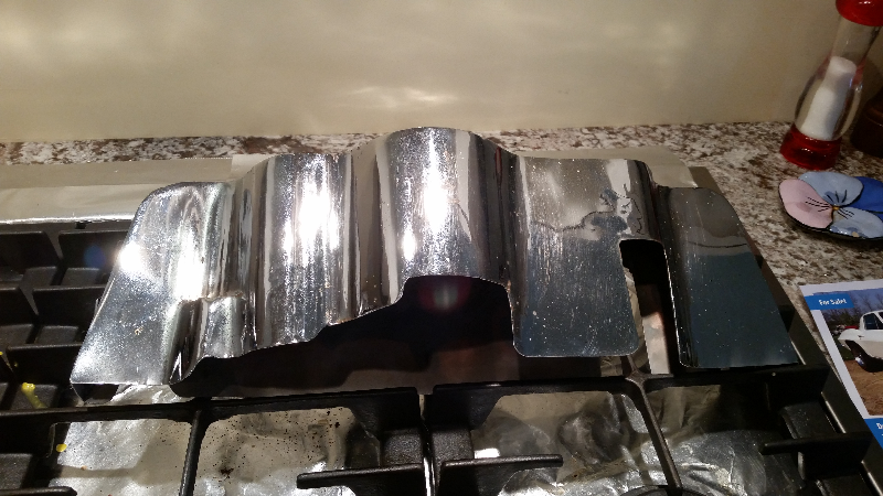
From: Doug Prince,
SoCal Chapter Advisor: This shield appears to be from a 58-61
carbureted Corvette which mounted the ignition coil on the passenger side.
Fuel injected Corvettes mounted the coil on the driver’s side.
From:
Larry Pearson, SoCal Chapter Advisor:
Cliff: If this isn't some sort
of a prototype, then someone went to a lot of trouble and expense to create
a top radio shield for the carbureted engines that could have been purchased
at any Chevrolet parts counter. I was able to buy this top shield from my
dealer well into the 70's. This top shield design was used on 1957 through
1962 radio equipped carbureted Corvettes. Fuel injection equipped Corvettes
had a much different looking top shield because of a different coil
location. I don't know what the 1956 top shield looked like, but it was
probably something like this unless it was some kind of carry-over from
1955. The original top shield for these years was made out of three
separate pieces of polished stainless steel that were spot welded together
to form the finished part. Your shield dates back to before 1968 when you
got it with your 1960 Corvette. It appears to be made up of at least five
separate pieces that were welded together and then chrome plated.
The original shields were
normally mounted to the engine with two chrome plated wing bolts in the back
and a chrome plated 1/4-20 hex head bolt on the top. The shield attaches to
spark plug wire support brackets in three different locations. The back
side had two slotted cutouts like the one shown in your photo. on the left
side of your shield. Some shields had a slot on one side and a round hole
on the other side. The one on my 1960 was done this way. The right side of
your shield has a big cutout that would not work with the wing nut, because
it is too large. Finally, there should be an oblong hole on the top surface
for the hex bolt to go. You have no hole there at all. So the way your
shield is configured it is beautiful, but it is not usable as a top radio
shield.
What is it worth? Unless you can
prove that GM made it as a prototype, I don't think that anyone would want
it. Reproductions of the real thing are readily available.
Larry Pearson
********
My name is Dennis DeVito. I am currently in the final
stages of my 1960 Corvette's Restoration Project.
My question is on the proper location of the Jacking
Instructions Decal and the Positraction Decal on the
Sparetire Coverboard.
I also have a Harrison Aluminum Top Tank Radiator, and
would like the Factory Correct location of the
Thermostat Decal's exact location on the which side of
the top of the Radiator.
Please respond.
Thank You
Dennis
From:
Larry Pearson, SoCal Chapter Advisor:
Dennis: Original top tank aluminum radiators are
very rare, and I have never seen one with the
paper "CAUTION" sticker in place. On the 1961 and
1962 aluminum radiators that use the separate
aluminum expansion tank, the sticker is on the left
(driver's) side and the Harrison metal tag is on the
right side. The CAUTION sticker on your radiator
should go on the opposite side from the Harrison
tag, probably the left side. The location of this
sticker is not "exact", and there is no
location specification in the factory Assembly
Manual. As a point of interest, this same "CAUTION"
sticker was also used on the 1960 Chevy sedans, but
it was applied to the steel header in front of the
radiator, and not on the radiator.
The
red Positraction paper label goes on the left
(driver's) side of the plywood spare tire cover and
the black jacking instructions go on the right
side. They are glued in place with a yellow rubber
cement type adhesive (like 3M weatherstrip adhesive
in the spray can) that was sprayed on the wood (with
lots of overspray) and then the paper labels were
applied over the adhesive. Both labels are
approximately centered between the edge of the board
and the center metal cover hold down cup, and are
approximately in line with the metal hold down cup.
Nothing precise here.
**********
Hi Bruce,
I have a quick question for you. I am replacing the radiator hoses on
our 1954 Corvette. I'm looking to find out the correct hose clamps. Are
they spring clamps or tower clamps?
Also, what are your thoughts about converting to a 12 volt system?
Thanks,
Virgil
From:
Bruce Fuhrman, SACC Secretary:
Hi again,
I researched your request for hose clamps at home and this is what I
found.
Two different clamps were used on early and late '54's. They are a flat metal
strap about a 1/2" wide. and it is bent outward about 90 degrees. A small
machine bolt fits through the holes to form the clamp. The second clamp is
still a 1/2" but it's center section has been stamped out of and
doubled around to form a center reinforcement. This type is shown on the
attached photo which was taken at Barrett/Jackson in Scottsdale this weekend
of an original '54 un-restored VIN # 1289 (early production). Disregard the
overflow tank small hose clamps which are Corbin spring clamps which were not
used until 1955.
Hope this helps.

Hi Virgil,
The conversion to 12 V is easy, I did it to mine about 20 years ago.
The 6v wire is larger so no problem there. Change the bulbs (all)
including the dash and doors., the clock if working to quartz, and the
starter and generator need to be rewound for 12V and keep the same
housings. The float in the gas tank needs to be changed, the voltage
regulator and most important add a resistor (porcelain) to the ign.
line to the points. Obviously the coil to 12V. The major expense is
the conversion of the radio to 12V. You will need to send to a radio
guy to replace all tubes, I paid $400. I did not replace the horns
since they were over $750 and when I use the horn, close your ears! I
found a 12V DELCO battery that was sealed and glued 3 yellow tops on
the top with the threads cut off.
Cheers,
Bruce Fuhrman
Cheers,
Bruce Fuhrman
**********
Looking for Diagrams/Schematics for the Trunk Latch “fiberglass piece” that
is Bonded to the trunk Floor, with the Latch…
Also other parts like the License plate Lamp/housing, and,, or course a
TRUNK LID….
Any info would be appreciated, AND, who may have some For Sale….
Thank you
From: Larry
Pearson, SoCal Chapter Advisor:
Sam: It sounds like your
car got rear-ended. You should be able to buy everything you need from
Corvette Central. They have an online catalogue at
www.corvettecentral.com, or you can call them at
800.345.3342. I have a hard copy of their catalog from 2010, and all your
needs seem to be there, and I assume that they still are. Another good
source is Paragon Reproductions, Inc., 800.882.4688,
www.corvette-paragon.com. This is from their 2004
catalog.
Larry Pearson
**********
Looking for help identifying the block drains for cooling system flush
on my 1959 283. Pics attached. Which are the drain plugs - front or
back? Also, any tips on accessing the lower radiator hose which seems
to require removal of the fan cowling.
Thanks!
From: Larry Pearson,
SoCal Chapter Advisor:
Clark: The coolant drain
plugs are the 9/16 inch steel plugs located in the middle of both sides of the
engine block. You need to remove the plugs on both sides of the block and open
the lower radiator drain petcock to completely drain the engine block. I do
not know what the front plugs on your block are for, and do not recall ever
seeing these plugs on any of the small block Chevys that I own. I own the
following original engine Chevys: 1956 265ci, 1960 283ci, 1962 327ci, 1975
350 ci, and 1992 350 ci. Your block does not look like any 283 ci block that
I have ever seen. But if it works, enjoy. Neat looking oil pan! The
original oil pan on your Corvette was a high capacity steel 5 quart pan (6
quart oil change including the filter). Even on the base engines. The
passenger cars had 4 quart oil pans, with a 5 quart oil change.
As far as the lower radiator
hose, you have to remove the upper and lower fan shrouds to get at the front
lower hose clamp. There is an access hole in the right front side of the
lower fan shroud but I have never been able to properly access the front lower
hose clamp through that hole. You can't get to this clamp from under the car
because the frame cross member is in the way. Use a good quality
replacement lower hose and it will last you many years.
**********
Gentlemen:
Does anyone have detailed specifications/dimensions on ’61-’62 seats. I
finally pulled my ’61 from the upholstery shop where they had it for 4
months and it is still not completed. They refurbished my seat frames added
new foam and recovered them. Seats look great but they do not fit
properly. Obviously they are “over-stuffed” for proper seating position and
convertible frame clearance (when top is down). I am fighting with them on
fix but it would be great if I had detailed measurements and clearances.
Any help is much appreciated.
From:
Larry Pearson,, SoCal Chapter Advisor:
Gary: There are no
"measurements" published anywhere. The seat assemblies were constructed and
upholstered in a separate facility and delivered to the assembly line ready to
install in the car. No photographs exist showing the upholstery workers
assembling the seats. Al Knoch Interiors has produced a video showing how to
install his seat covers over his seat foam and these videos cost about $100
each. Maybe you could start with this. Did you buy new seat foam from Al
Knoch to install over the refurbished seat frame? Back in 1961 Motor Trend
did a road test on the 1961 Corvette and it shows how the seats looked and
fit when the car was new. The original seat foam was molded out of latex foam
rubber which deteriorates when exposed to air over a period of time. Did your
upholstery shop add modern plastic foam rubber cut from a sheet over the
original latex foam making the seat too wide to fit in the car? The center
pleated insert originally had a distinct depression in it. Most upholstery
shops over-stuff this area making it appear convex rather than concave. But
it should still fit in the car. The seats should be narrow enough that the
seat can be moved back and forth the entire range of the seat track without
"jamming" against the center console. If it jams against the center console,
maybe you could remove the "hog rings" that attach the seat cover to the frame
in that area and remove the excess foam rubber and then reinstall the hog
rings (they can be re-shaped and re used).
You say that the seats "look great". That's a good start.
Larry Pearson
**********
I recently lost the motor in my 58 283 Fuelie (rod thru the oil pan)
after only 450 miles on a rebuild from a machine shop. I will be
replacing it with a GM 350 290hp long block using 462 camel hump
heads to raise the compression and to keep some what of an original
look. My question is since the new blocks do not have a road draft
tube can I get away with using a vented oil breather cap on the oil
fill tube to vent the engine? The Fuel Injection unit should work on
that motor with that cam but I would rather not have to put a pvc or
breather on the valve covers to keep a stock look. What affect will
this have on the motor? I do not want to put a used rebuilt motor in
the car again.
From: Doug Prince, SoCal
Chapter Advisor:
Mike,
Your original engine block
had a provision for a road draft tube to draw clean air through the oil filler
cap although only hydraulic cam engines had this type of oil filler cap. Solid
lifter engines did not have an oil filler cap that would breath fresh air into
the crankcase. In order for your replacement engine to vent itself you would
need to add a PCV valve somewhere on one of the valve covers which would require
some modification along with an oil filler cap that would permit fresh air into
the engine. These oil filler breather caps are available from various after
market Corvette parts suppliers. In order to preserve the original look of your
valve covers would require extensive modifications of the replacement engine
block to provide a PCV valve that first appeared in 1961/1962 RPO 242 PCV valve
applications. After market engine blocks that do not have the road draft tube
provision are a crap shoot but can be made to work if you are willing to modify
and add a PCV valve to one of your original valve covers.
**********
I’M LOOKING FOR A REPLACEMENT 6” X 9”SPEAKER THAT WILL FIT
MY 62. THE PROBLEM I’M HAVING IS THAT THE 4 STUDS ON THE
DASH HOLD DOWN ARE NOT LONG ENOUGH TO ACCOMMODATE THE
AFTERMARKET SPEAKERS THAT ARE ABOUT ½” THICK AT THE MOUNTING
FLANGE AND THERE IS NOT ENOUGH LENGTH ON THE 4 STUDS TO GET
THE NUTS ON. I ASSUME THE OEM UNITS WERE CLOSE TO FLUSH THUS
PROVIDING ENOUGH LENGTH TO SECURE THE HOLD DOWN NUTS. I SEE
AFTERMARKET SMALL DUAL SPEAKERS MOUNTED TO A 6” X 9” PLATE
BUT I’M NOT SURE HOW THICK THAT PLATE IS OR IF IT WILL WORK
WITH MY STOCK HOLD DOWN STUD LENGTH. ANY HELP WOULD BE
APPRECIATED.
BILL
From: Larry Pearson, SoCal
Chapter Advisor:
Bill:
Chip Werstein offered some good suggestions, and I have
some additional thoughts.
Do you
have the original speaker? If so, use a razor blade and
trim the thickness of the cardboard seal to match the
thickness of the original speaker cone. The 1/2"
thickness that you report is way too thick. If you have
the original speaker and the cone is torn with no missing
pieces, it can usually be repaired using Elmer's white
glue and toilet paper. Yes, toilet paper. It works
great. If you want it to look black, use a black felt tip
pen to blacken it. Or as chip suggested, look for someone
to re-cone it. Whatever speaker you end up using, the
original transformer must be used or the radio output
transistor will immediately burn out if you connect the
radio output directly to the speaker voice coil. The
radio output transistor is directly connected the
transformer primary coil, which is part of its bias
circuit, and the four ohm resistance of the voice coil is
much too low.
I do not
recommend dual-cone speakers. That only complicates
things from an impedance standpoint and may destroy the
radio output transistor or cause the output to distort.
From: Chip Werstein,
SoCal Chapter Advisor:
Bill,
I have installed many speakers in C-1 Corvettes and never experienced this
problem. I would check 3 things.
1. Are the 4 studs on your speaker grill oval broken or somehow too short?
2. Is there excess foam on the dash pad which prevents the oval from going
down as far as it should?
3. Did you slot ( or make oval) the stud holes for the speaker grill oval?
If you didn't, the vinyl on the pad will hold the oval up too high.
Perhaps you could take an original speaker and have it re-coned.
**********
Am rebuilding 1960 and cannot find the castle nut that holds pinion yoke
onto the pinion shaft. Tried buying a 7/8" fine thread nut at machine
shop, but the threads seemed too coarse. Anybody no what the nut size is
(thread count) and where I can get one?
Thanks,
Tom
From:
Larry Pearson, SoCal Chapter Advisor:
Tom: Corvette Central has
this nut under catalog number 582107 and comes with a new washer. It actually
is a locking nut and you are supposed to use a new nut and washer every time
you remove it. The nut is pinched to make it resistant to coming loose.
According to the ST-12 shop manual, page 4-10, the nut is to be torqued to
150-190 foot-pounds. I suggest that you use a large pipe wrench to hold the
"pinion yoke" from turning while torqueing the nut.. Originally they had a
special tool to hold it and this tool is shown on page 4-10. It would be
easiest if you tightened the nut with the differential installed in the rear
axle housing. The pipe wrench can then rest against the garage floor. I
suggest that you install a new pinion seal, because it can leak, and then you
can do the whole job over again.
Larry Pearson.
**********
Hello,
NCRS Member number 63986, not a member of SACC yet.
I have a 1962 Corvette Survivor, 327 CI engine, 250 HP, 4 speed transmission.
Car was running find up to a couple of days ago. Battery charged, fuel in
car, when you crank it, turns over, but nothing happens, will not start.
There is a brown wire loose under the dash, might be from the ignition switch,
however, I have a colostomy and am not able to look under the dash. Going to
get this bag off my side
November 3, 2017.
Everything is the same on car, most likely something simple but??????
Any suggestions or comments welcomed.
From: Larry Pearson,
SoCal Chapter Advisor:
Steve: The 18 gauge
brown wire loose under the dash is most likely the problem. This wire goes
from the lower part of the center connector on the ignition switch and
the other end goes to the ballast resistor under the hood. The brown wire
from the windshield wiper motor also connects to the same lug on the ballast
resistor. The brown wire at the ignition switch locks into the plastic
connector and is retained by a tab that is bent slightly up on the crimped-on
connector. This is one of three wires that go into this connector. Make sure
that the brown wire connector locks into the plastic connector, or this
problem might repeat itself.
Larry Pearson
**********
Hello,
I have a 1959 Corvette with a single Carter 4 barrel
WCFB on the 283. I have the passenger side exhaust
manifold casting # 3750556 that has the hole for the
inner choke tube, but no choke tube. The casting does
not have an exit hole bored through at the base
opposing to top hole. I am confused, I see there is a
lower choke tube that can be purchase, but if I press
it in and attache the upper tube to it, then the
Carter choke would be directly connected to the heat
and pressure of the exhaust gasses - this doesn't seem
correct to me. Am I missing something? Is the choke
tube that is pressed into the manifold open at the
other end in the exhaust allowing the pressurized gas
to flow to the choke body?
Any description or diagrams would help. I've searched
on the internet and read vague discussions, but I am
perplexed by this.
From:
Larry Pearson, SoCal Chapter Advisor:
Dane: All Chevrolet V-8 engines starting in
1955 with a carburetor had what is known as a heat
stove in the passenger exhaust manifold. The
purpose of the heat stove is to heat up the ambient
air being drawn into the automatic choke housing by
a manifold vacuum passage inside the carburetor.
This heated air causes a bi-metallic coil inside the
choke housing to heat up and twist open the
automatic choke valve inside the carburetor air horn
and, through linkage, turn a fast idle cam on the
base of the carburetor to slow the cold fast idle.
Starting in 1957 the heat stove consists of an
approximately 6-inch stainless steel hollow tube
that is pressed into this exhaust manifold through
holes bored in the top and bottom side of the
manifold at an angle and in perfect alignment. Your
exhaust manifold must have both of these holes.
They never made an exhaust manifold with just the
top hole, as you seem to be telling us. If your
manifold is defective, you will have to buy a
replacement manifold with a good tube in it. Or try
your luck in drilling the lower hole in alignment
with the upper hole. Or plug the holes and use an
after market electric choke housing. The solid axle
fuel injected engines had manifolds without the heat
stove. These manifolds without the heat stove are
very rare and valuable. The cast-in part numbers
are the same for both manifolds.
Sometimes the tube burns through and the tube must
be replaced. You don't want hot exhaust gasses
being drawn into the choke housing. Replacement
tubes are available through Corvette Central. Be
careful if you are drilling out the remains of a
burned out tube that you do not enlarge the holes in
the cast iron manifold or the replacement tube will
not stay in place. Use a pin punch to drive out the
old tube remains. The upper end of heat stove
connects to the carburetor choke housing with a
length of 1/4 brake line and a compression ferrule
and special brass hex nut. The lower end of the
stove tube is open to ambient air. In 1962 a
special lower tube assembly connected into the lower
end and came up and transitioned to a rubber hose
that pushed over a brass tube in the side of
the carburetor air horn, thereby causing filtered
air to enter the choke housing.
Larry Pearson
**********
hi, i have a 62 corvette and the tach only goes up to about 12 to 1500 rpms,
i have checked the cable connections and all seems fine. any thoughts
besides replacing the tach ?
i really do not want to pull out the cluster !! thanks in advance for any
thoughts charles
From:
Doug Prince, SoCal Chapter Advisor:
The tachometer in your Corvette operates on a bunch of spinning
magnets that register RPM. Your tachometer is history and needs to be rebuilt
by a reputable rebuilder. On the West Coast many people rely on Valley Vettes,
Mike Poirer in San Diego, 619-461-1952.
From:
Larry Pearson, SoCal Chapter Advisor:
I have some additional
thoughts on this. The solid axle tachometer operates just like the solid
axle speedometer, except that it indicates twice shaft speed. A spinning
magnet assembly driven off the tachometer (or speedometer) cable operates
inside an aluminum cup called the speed cup and causes the cup, which attaches
to a shaft that the pointer is on, to turn against a coil spring. The unit is
calibrated by charging or discharging the magnetism in the tips of the
spinning magnet assembly. The problem usually is with wear in the bushings
that support the spinning magnet assembly. Or the problem can be with the
speed cup shaft bushings. Or both. Because of this, you should contact a
local speedometer shop that can repair old mechanical speedometers to get it
rebuilt. Corvette Central offers a repair service for solid axle speedometers
and tachometers, and they can do the repair for you no matter where you live.
It is hard to find parts for these early units and a local shop might not be
able to repair your unit. If you have a local shop rebuild it,
be sure to tell them to
calibrate it to read twice shaft speed!
Larry Pearson
**********
Hi, Can you guys help me with some information on the correct speed nuts for a
set of 58 trunk spears? I have looked almost everywhere but I cant find anyone
that knows. Any help would be greatly appreciated.
Thanks for you time,.............E McIntosh
From: Larry Pearson, SoCal Chapter advisor:
The 58 trunk spears are
retained by PAL nuts, not speed nuts. The PAL nut is a self tapping hex
headed sheet metal formed nut that cuts its own threads on the trunk
spear studs and they have "PAL" stamped on the flange area. They come in
various sizes depending on the size of the stud they are being threaded on. I
think that you need a 1/8th inch size. The inside cavity of these nuts were
filled with grey 3M Strip Caulk to prevent water leakage into the trunk.
Contact Corvette Central to see if they sell them. If not, contact me and I
will send you some at no charge.
Larry Pearson
**********
I AM A NEW MEMBER # 3993 AND HAVE A FEW TECHNICAL QUESTIONS MAYBE SOMEONE CAN
HELP ME WITH.
1)
MY FACTOR HUBCAPS SEAM TO BE TURNING ON THE RIMS AND STARTING TO PINCH
THE AIR STEMS. THE RIMS HAVE 4-BUMP-OUTS TO HOLD THE HUBCAPS BUT THEY STILL
TRY TO ROTATE FOR SOME REASON.
2)
I CURRENTLY HAVE AN OLD AM/FM-CASSETE PLAYER (WONDERBAR IN STORAGE)
BUT THIS RADIO IS SHOT. I AM LOOKING FOR A REPLACEMENT AND THERE SEEM TO BE
MANY OUT THERE. HOWEVER MOST ARE HIGH-TECH WITH ELECTRONIC PRESETS ETC. I
DISCONNECT MY BATTERY EVERY TIME AND DON’T WANT TO DEAL WITH FLASHING LIGHTS
AND HAVING TO RE-SET RADIO STATIONS ETC. DO YOU KNOW OF A UNIT THAT COULD WORK
FOR ME?
THANKS FOR YOUR TIME!
From:
Chip Werstein, SoCal Chapter Advsor:
Bill,
Don't know what the problem could be with your
hubcaps..................unless they are reproductions and not originals.
I have heard that repros can fall off.
I have 2 reproduction am-fm stereo wonderbar with radios with inputs. They
work great and keep their settings when the battery is disconnected.
Contact Len Marino 626-358-1466 to purchase one.
**********
Hello,
I have, ready to install, in my (late off the line) 1954 Corvette,
a battery tray with 2 diagonal bars extending out.
The worn out battery tray in the car is the flat type.
How is it best installed?
Are both types of trays acceptable for a '54?
Also, have you found an aceptable tie-down
for an Optima Red Top battery?
Please advise.
Thank you,
Bob
From:
Bruce Fuhrman, SACC Secretary:
Hi Bob,
To my knowledge there was only one type battery tray used in the '54.
The 2 diagonal bars straddle the frame and are attached with bolts to the
frame (see photo), I also included a top view.
I do not have any info on the Optima Red battery installation, but be
creative!
Cheers,


**********
Should my powerglide transmission
on my 1960 Corvette start in "both" neutral and park or in "either" neutral or
park. It presently will only start in park. Thanks, Wayne
From: Joe LeMay, SoCal Chapter:
The Performance Verification for C1s says the car starts in both park and
neutral.
**********
I have a 1962. My question is about the tach gauge. There is a low RPM and a
High RPM gauge. Are these tach gauges related to the HP? What determines if a
low or high is correct for my car?
Best regards / Mit freundlichen Grüssen / un saludo /
诚挚问候
Ron
From
Doug Prince, SoCal Chapter Advisor:
RPM red line is directly related to engine horsepower. The
250 and 300 horsepower cars are equipped with a hydraulic camshafts and use the
low RPM red line tachometer. The 340 and 360 horsepower engines had solid
lifter camshafts and came with the high RPM red line tachometer.
**********
I recently saw a C1 vette with cove moldings and inserts like a 61 but the
driver told me it was a 62 vette. Was the trim an option or could it have been
added to the 62 by the owner? Thanks
From:
Brad Bean, SACC Vice President: Stainless cove separation trim was
not available, from the factory on a 62 Corvette. Of course, once it left the
factory, the owner could have done what they wanted...
From:
Doug Prince, SoCal Chapter Advisor: Only added to the car by an
owner as GM did very few COPO cars in the day as only the very high ups in the
corporate ladder could get a one off special Corvette from St. Louis. Maybe the
owner was clueless as to what year he had!
From:
Larry Pearson, SoCal Chapter Advisor:
Jeff: The 1962 had a raised
bead instead of stainless steel moldings like 1956-1961 Corvettes had. It
would be very hard to mount the 1961 moldings over this raised bead and have
the result look good. The raised bead cannot be ground smooth without
the certainty of going completely through the fiberglass in the areas of the
raised bead. If this car really was a 1962, I suspect that the front
fiberglass and door fiberglass was replaced with 1961 panels.
Larry Pearson
**********
Trying to install antenna cable that runs inside the rocker , what the best
way to get the cable from the trunk to the dash? Thanks
From:
Bruce Fuhrman. SACC Secretary: The method of
placing the cable is not available in any books I have, however is easy to place
under the carpet and behind the seat.
Bruce Fuhrman
From:
Larry Pearson, SoCal Chapter Advisor:
Lucio: There is a 1953-1955
Corvette Assembly Instruction Manual (AIM) that is available through NCRS or
the major Corvette parts suppliers, and you should obtain a copy if you have
one of these cars. This publication was prepared by Chevrolet engineering to
instruct the assembly line in how to build the car. This publication is all
drawn by freehand, and there are no page numbers, but I think that you will
find it to be very helpful. The antenna lead was run through the rocker panel
on the passenger side, along with the main wiring harness. Apparently when
the body was being constructed a pull wire was included to assist in the
installation of the main wiring harness and the radio antenna cable. Running
the cable under the carpet would be the easiest approach, but this is not how
the factory did it, as you will see when you get your AIM.
Larry Pearson
**********
My question is I would like to know detail specifications on the 1958
convertible top weather stripping,fastening for it,screw type and size of all
retainers,and procedures for adjusting the top to the body and the windshield
Thanks
From: Larry
Pearson, SoCal Chapter Advisor:
For help understanding the
1958 Corvette Convertible top mechanism and installation, you need to refer to
the official Chevrolet Shop Manual for all C1 Corvettes, Corvette Servicing
Guide, Publication ST-12. This publication can be obtained from most of the
Corvette Parts Suppliers, and is a “must have” for C1 owners. The information
you need is found in Section 1, BODY, pages 1-31 through 1-34. It is not
complete, and I do not know any source to go to for all the small details.
These tops are not easy to install and I suggest that you go to an experienced
upholstery shop to have the work done. It is virtually impossible using words
to explain how to install one of these tops. Al Knoch sells videos that teach
you how to install these tops. He also offers a top installation service at
Meets he attends. Corvette Central sells all the weatherstripping and hardware
you will need, and their catalog illustrations will help you figure out what you
need and where it goes.
The original weather
stripping used on the 1956 through 1958 Corvettes was cloth covered with molded
in mounting studs and steel reinforcements, and has been discontinued since
1959. You have to use the 1959 through 1962 style weather stripping and
attaching hardware illustrated in figure 79 on page 1-74. Each of the six
rubber weather strips on the side frames are attached using black-painted steel
retainer strips and #8-32 round-head Phillips screws and special weld nuts as
shown in figure 79. There is also a header weather stripping that installs with
its own metal retainer and special screws and the rear deck bow weather strip,
which is not illustrated. The header and rear deck bow weatherstrips don’t get
installed until after the top fabric is installed to them. The rear deck bow
weather strip attaches with screws and staples. There are also two (left and
right) short weatherstrips that bridge the gap between the top frame and the
rear deck bow. These attach with screws and 3M weatherstrip adhesive, and are
installed after the top fabric is in place.
Before attempting to
install the top frame, every part of it must be painted and properly shaped (not
bent). The frame parts are painted semigloss black and the header is gloss
black. There are tacking strips (also called trim sticks) in the header, rear
window bow and deck lid bow which must be in serviceable condition before the
top fabric can be installed. Tacking strips are petroleum impregnated (to make
them waterproof) heavy cardboard strips that accept staples or tacks to hold the
top fabric to these bows. They usually need replacing or repair. All pivot
points must be lubricated with grease or 30w oil so they move freely.
To install the top frame to
the car body, first install the side weatherstrips to the top frame using the
metal retainers and special weld nuts on the inside, as shown in Figure 79.
Install the top frame to the car body a using the hardware shown in Figure 71
and adjust the frame up and down and back and forth until it fits the side
windows perfectly when the windows are all the way up. The side frames attach
to the front header using slotted holes to assist in making the adjustments.
The door window stops must be properly adjusted so that the side windows go up
the proper amount. Not too high or too low. If you have a hard top, use that
to adjust the window stops so that the side windows go up the proper amount.
The linkage that goes up to the center pivot point on the side frames us used to
raise the pivot point so it follows the shape of the side window frames. That
is all it does. Do not proceed with the top fabric installation until the top
frame fits the side windows as perfectly as possible. Things will only get
worse once the top fabric is installed.
I hope this information
gets you moving in the right direction. Get the Al Knoch video if you want to
attempt to do the top installation yourself.
Larry Pearson
**********
1960 vette, rear leaf spring. I am
replacing both. the front shackle, is that large bolt pressed in, it's threaded
on one end only. how do you get that out of the schackle, hammer??
From: Chip Werstein,
SoCal Chapter Advsor:
Charlie,
The head of the shackle bolt is serrated so it won't spin in the bracket when
you tighten the nut. In many cases it is rusted into the bracket. You probably
can remove it with heat but the bracket and bolt my not be reusable. Worst
case scenario.....use a cutting torch to cut the bolt out of the bracket. Both
parts are available new from Paragon or Corvette Central. Note, I suspect it
goes without saying that the spring assemble with front bracket attached must
be removed from the chassis in order to drive the bolt out.
Chip Werstein
**********
Hello SACC Tech
Im not a member,thought I would still ask.
I have a new press molded jig built front end for 62 corvette,I asked the
Corvette Image this a.m they do not drill because not everyone wants them.
The holes for top fender S.S were not drilled,which has not been to hard to
do. But the hard part ! has been the CORVETTE script and emblem above.
Is there a Reliable template out there ? This is difficult to do
straight at correct location. Help, car is in paint shop now.
Thanks
walt
From
Bill Huffman, Michigan Chapter President:
Walt,
This is a common problem when replacing original body panels.
Make your own template using stiff paper to locate the holes on your original
panels, then transfer to the new panel.
Good luck with your project,
Bill Huffman, Pres.
Michigan Chapter SACC
**********
I have a 1958 fuel injected 250 HP corvette, that has been rebuilt from the
ground up. We are having difficulty with the full injection unit. It has been
rebuilt by known specialists (!) , It stars cold easily but when it warm up it
stalls and won’t start.? Where do we start?? Thanks Ken B in Vancouver
From:
Doug Prince, SoCal Chapter Advisor: Well join the crowd with FI
cars that won't/don't run in the heat. The problem is todays 10% gasohol
gasoline which boils and then percolates at 40 degrees less than pre gasohol
fuel did. The copper spider lines of FI cars are excellent of transferring
engine heat and causing the fuel to percolate. If under hood engine
temperatures reach or exceed 180 degrees you will consistently have this problem
and there are no known easy cures. Not sure if Canada has gasohol but I am sure
it does as this problem is rampant in the Southwestern United States. Racing
fuel is an option but is crazy expensive and in California is illegal to use on
surface streets and highways. I tell my customers to just "park it" if the
ambient outside temperature exceeds 90 degrees as there is no solution to this
problem.
**********
Hi, I need to know the tan paint color/code for the top bows on my 55
Vette.
I,m closing in on finishing the restoration this is one of the few
item left to do.
Thanks.
Larry
From:
Bruce Bruce Fuhrman, SACC Secretary:
There are no codes available in any of my books for the '53-'55 metal bows for
the top. I was able to match the color perfectly by selecting several
Beige spray cans from my local hardware store and checking
the lids to the existing bow.
Good luck.
**********
Hello, , Just rebuilt the steering box on my '62 C1. . That was easy
enough with the Joe Calcagno instructions. .
. . Question is, The spring in the drag link suggests it should be
tighter than just zero clearance. . What is the correct "tightness" ? ?
From:
Chip Werstein, SoCal Chapter Advsor:
Consult you ST 12 Corvette shop
manual......page 9-3.
"Tighten plugs snugly to remove all end play of ball. Back off plugs 1/4 to
1/2 turn plus amount necessary to insert cotter pin."
Chip Werstein
**********
1962, is the license plate bracket, bumper reinforcement, painted black or
body color? Thanks for your help.. Rear bumper
From:
Chip Werstein, SoCal Chapter Advisor:
Semi gloss black
Chip Werstein
**********
Hi:
I have one
more question that you probably know the answer to. If I have the ignition
on, without the engine running, the ballast resistor gets extremely hot. Hot
enough to melt the insulation on the wires attached to it. Is this normal? I
know that without the points opening and closing, the current through it is
constant but should it get that hot? No caution to not have the ignition on
without the engine running in the owner's manual.
Thanks,
Chuck
From: Larry Pearson, SoCal Chapter Advisor:
Chuck: If you leave the
ignition on with the engine not running and the points in the distributor
happen to be closed, and you leave the ignition on for some period of tine,
both the ballast resistor and the coil will get very hot, and you will
discharge the battery. This could be damaging to both of them, and you should
avoid doing this. I have not heard of the resistor getting so hot that the
insulation melts on the connecting wires. If you are running some kind of
test and you want to leave the ignition on, "bump" the starter until the
points are open, as evidenced by a low ammeter discharge reading.
If you are using an
original "091" coil (these numbers are embossed on the side of the coil), you
are supposed to use a ballast resistor of 0.5 ohms (marked with a black dot on
the metal bracket). If you are using a service replacement "202" coil, you
should be using a 1.5 ohm ballast resistor (marked with a blue stripe). If
you are using an after market coil, I would play it safe and use a 1.5 ohm
resistor, which should not cause so much heating.
**********
I
can't figure out how the clips go for the chrome on the glove box, 1956
Corvette.
-William
From: Bill Preston, Red River Chapter Advisor:
The
aluminum trim clips (Part # 14818) for the Glove Box Door are round on two
opposite corners and square on the other two corners
with an interference threaded hole in the middle. It takes four clips. You
insert two clips inside the back channel
of each door stainless trim pieces with the narrow sides parallel to the
edges. Then rotate the clip 90 degrees clockwise
until it is seated under the lip edges of the trim piece. (The top of the trim
strip must be held toward the upward
position and the clip must be rotated clockwise to keep from unseating the
clip when the attaching screw is tightened)
The clips should be located to line up with the holes
in the glove box door. Then attach using a #10-24 screw with a washer head
The 2 Short trim pieces below glove box door are put on by attaching NSS
Clips to
the outside of each side of the
glove box compartment (separator) (with
the friction clip toward the sides) using the 10-24 hinge-mounting bolts
with counter-sunk head. Then put washer & nut on inside of glove box. The
bottom stainless trim pieces can then be slid
onto the clips since they have an open bottom end
The 2 top stainless trim pieces must be snapped onto 2 NSS clips on each side
that are mounted directly to the fiberglass with sheet metal type screws (with
the friction clip toward the sides), These pieces are closed on both ends
making it necessary for you to
snap them onto the clips.
Bill Preston
**********
need
some help locating choke connector rods for my 54. 115-221 is part number in old
tech manuals. also my wiper motor is original and needs rebuilt, is there a kit
to do this, or someone who rebuilds.
Thanks very much,
Mike
From:
Bruce Fuhrman, SACC Secretary:
Hi Mike,
I assume you are referring to the rod that connects the mechanical movement
from the cable to the choke plate at the bottom of the carburetor. These may
be difficult to find. Check
www.vettegal.com
she has a lot of carburetor parts and just have some laying around.
Good luck.
Bruce Fuhrman
From: Chip Werstein, SoCal Chapter Advisor:
Mike,
Your wiper motor can be restored by Valley Vettes in San Diego.......Mike
Poirier. He does instruments too. I have used him for many years.
619-461-1952.
**********
I need more help?
Again I have Two 1962 Corvette .
One has steering column About 47 inches long.
The other column 45 inches long.
Can you please tell me witch one is correct?
THANK YOU
Sthua
From:
Chip Werstein, SoCal Chapter Advisor:
Sthua,
I just measured a 1957 steering column I have out of the car. Measuring the
mast jacket from the steering box is 49". The shaft extends approx 21/2 " past
the end of the mast jacket. I don't know the actual length of a 58 to 62
column, but I know for certain it is shorter, probably by about 3".
Chip Werstein
From: Bill Huffman, Michigan Chapter President:
Sthua,
You have two 1962 Corvettes with different length steering columns.
The original one should have the VIN plate resistance welded to the top
surface of the tube just forward of the cowl, under the hood. The VIN #
should also match your vehicle title Vin Number.
I'm guessing that the longer one is in the car with the shifted transmission
and the distorted front motor support bracket.
Wrecked cars can get strange parts.
Your 1962 assembly manual should show the correct GM steering gear asm P/N.
Regards,
Bill Huffman, Pres.
**********
What is the best way to adjust the steering box on a 1959 corvette it has to
much play in steering wheel thanks for any help
New member Richard
From:
Bill Huffman, Michigan Chapter President:
Richard,
The steering gear adjustment is a slotted screw & jam nut on the left side of
the gearbox.
Loosen the jam nut and turn the adjustment screw in or out till you achieve
minimum free play then retighten the jam nut.
In order to make adjustment easier on my C-1s, I drilled a 1/2 inch hole in
the left side inner fender in line with the adjustment screw.
However, a 58 year old steering gear set may well have extremely worn/flatted/brinnelled
gears and may require rebuild.
In addition, there are several other components that affect steering freeplay
which need to be checked.
Loose wheel bearings, loose/worn kingpins, worn/loose drag link, loose third
arm bearing asm & loose tie-rod ends all contribute to freeplay in the
steering wheel.
Good luck with your project,
Bill Huffman, Pres.
**********
Will a 61 speedometer fit a 58
Corvette
From: Chip
Werstein, SoCal Chapter Advisor:
The 61 speedo will bolt right in to
the 58 but I think numbers on the face and the pointer are slightly different.
Chip Werstein
**********
I have a 62 Corvette, 300 HP with a Carter AFB. My question is about a
sticking choke. The choke opens fine as the car heats up. The problem is
that the choke sticks open. After the engine is cold and I tap the
accelerator, the choke won't slam shut. I always have to take the top off the
air cleaner and push the butterfly closed while I hold open the accelerator.
I've checked everything and it seems to be that the metal piston inside the
choke housing binds in the cylinder. I've tried everything from silicone
spray to emery paper but nothing seems to fix it. I could buy a new choke but
I'd rather fix it and save money.
Thanks,
Chuck
From:
Chip Werstein, SoCal Chapter Advisor:
I
am experiencing a similar problem on my 62 340 hp car. All parts and linkage
operate freely, but when cold the choke wont close and as a result the fast idle
won't set either. Purely by accident, I left the three screws which hold the
choke cover to the housing somewhat loose and the choke began to work
perfectly. I am now trying to find the right "tightness" for those screws. I may
attempt to put a 2nd gasket between the choke cover and housing. My problem
isn't solved yet, but I think I'm getting close.
**********
I have mufflers and exhaust pipes bought in
early 70’s for my “60” and never used. The pipes have the tags and the
mufflers are still in the boxes. I’m going to put them up for sale but would
like to verify the numbers. I have searched on line and can’t find any listing
for parts this old.
Is there someone I can contact or do you have
this information.
Part Numbers are: 3752558
3752555
3735167
3735164
3815511
3815512 Thanks, Charlie B.
From:
Larry Pearson, SoCal Chapter Advisor:
Charlie: The exhaust system
you have was for the base engines (230hp & 245hp) and uses the oval muffler.
Each side of your dual exhaust system was serviced with five separate parts,
listed from the engine to the rear bumper outlets: exhaust pipe, extension
pipe (adapts muffler to the exhaust pipe, about 2' long), oval muffler, tail
pipe, and tail pipe extension (about 19" long and adapts the tail pipe to the
bumper opening). Originally the mufflers were manufactured with the extension
pipe made as part of the muffler, but the mufflers were serviced without this
extension, so a separate part was needed to connect the exhaust pipe to the
muffler. Here is how the part numbers apply:
Exhaust pipe: 3735167 (L.H.),
3735164 (R.H.); Extension pipes: 3815513 (L.H.), 385514 (R.H.); Mufflers:
3815511 (L.H.), 3815512 (R.H.); Tail pipe: 3752555 (L.H.), 3752556 (R.H.);
Tail pipe extension: 3762440 (L.H. & R.H.). The tail pipes and tail pipe
extensions were the same for all engines. Also, if you are using the oval
mufflers with the solid lifter engines, the extension pipes and the oval
mufflers would work on those applications. The exhaust pipes for the solid
lifter engines had a crossover pipe arrangement, but otherwise were the
same shape and diameter as the base engine application.
I can find no reference to
your 3752558 part. Maybe it is 3752556. To complete the exhaust system you
have, you are missing the extension pipes and the tail pipe extension pipes.
The mufflers, without the extensions, were probably also used on the passenger
cars.
Larry Pearson
Charlie: Some additional
information since you are planning to sell these parts. I have a 1972
Chevrolet Corvette parts book, and it gives other applications for your
exhaust parts. The mufflers are listed as the low noise service parts for
all 1955 (V-8) through 1962 Corvettes. This would apply to the high
performance engines also. The exhaust pipes are listed for all 1957-1962
base engine Corvettes. The tail pipes are listed for 1957 (without the
extensions) through 1960 Corvettes (the 1958-1960 Corvettes would need the
extensions, which you don't have).
Larry Pearson
**********
There are two pieces of ss trim on the side of the car, one right behind the
gull wing and one on the door . are they side specific? If so how can I tell
rt from left?
Gil
From:
Bruce Fuhrman, SACC Secretary:
Hi Gil,
They are not side specific. The tapered edge on each strip belongs at the
hinge door opening. This provides clearance when opening the door. If you do
not put the tapered edge here, the door will not open without bending the s/s
strips.
Cheers,
**********
Hi
I have a 1962 Corvette just bought.
I found after I started Driving it, Bad Vibration in drive train.
I put it on a lift and found that some body shimmed the shifter to fit
through floor hole.
They also Shimmed one side of trans Mount , Transmission tail touching X
Frame.
Bought new trans Mount , Installed Mount & took 15 washer out so
shifter bolted up were it should .
Transmission Mount would not bolt in right, so I look into motor
mounting found by shimming up right side 3/4 inch
transmission moved into alignment . So I pulled Rad , Fan , Hoses out of
the way found Engine Tower Motor Mounts
Look uneven R/S tower angled down and lower than L/S tower.
Looks like engine needs to come Forward 1/2 Inch.
Can you help me ? I need the Spec for front frame rails and Engine
Tower Motor Mount?
Any help would be Appreciated
THANK YOU
Sthua
From:
Bill Huffman, Michigan Chapter President:
Stash,
Unfortunately, you might be one of those Corvette lovers who bought somebodys
cobbled together wreck.
If you scroll thru the technical help page, you will find my answer to Anthony
regarding the location of the motor mount bracket location on his '59 frame
rails. The same procedure is applicable to your '62.
(Anthony's question and answer) follows:
We have a 59 frame that the "L" brackets (both top and bottom) that mount the
engine supports bolt to, have been destroyed and we would like to find the
exact location for placement of the new "L" bracket. We have been unable to
this point to find reference material with specifications & measurements. Can
someone help with some direction to acquire these specifications or patterns
that will position the brackets properly.
Eye balling of the location from another built frame has proven difficult in
being precise.
Thank you
Anthony
-----------------------------------
From: Bill Huffman, Michigan
Chapter President:
Tony,
I had the same problem in restoring a 1960 that had been "modified" into a
straight front axle dragster.
I also had no luck in finding correct dimensions for locating the "L"
brackets.
Since the transmission crossmember & trans support were intact, and the
transmission / bell housing / engine block / front motor mount support
bracket are one structural member, my solution was to literally bolt the
components up to the frame.
I used a floor jack to raise the front of the block, with the transmission
support acting as a fulcrum.
With the all the front motor mount components finger tight, the "L" brackets
will pretty much locate themselves..Since my frame was sand blasted, I found
grind marks where the previous brackets were ground off confirming the
location.
Make sure the your components are centered in the frame and the vertical
brackets are perpendicular to the frame horns before clamping the "L"
brackets for welding.
Good luck with your project,
Bill Huffman, Pres.
Michigan Chapter SACC
**********
Hi, I would like info on becoming a member. Question: 1962 .
Is there a compression connection in the manifold?
Also, I have a small exhaust leak.
From:
Larry Pearson, SoCal Chapter Advisor:
Don: The tube from the
carburetor to the exhaust manifold has a compression fitting under the nut
that threads into the automatic choke cover. The other end simply pushes into
what is called the "choke stove", which is a steel tube pressed into the
exhaust manifold at an angle and is exposed to the hot exhaust gasses which
heats up the air being sucked into the automatic choke assembly via manifold
vacuum present under the choke cover. After years of use, this choke stove
tube can burn through, causing an exhaust leak into the automatic choke
assembly. Service replacement choke stove tubes should be available from
Corvette Central. To install the new tube, you must carefully drill out the
old tube, being careful not to enlarge the holes in the cast iron exhaust
manifold.
Prior to 1962, the lower end
of the choke stove tube was open to the ambient air, and whatever dust and
dirt that might be present in that air. Starting in 1962, a lower tube
assembly having a bracket on it that attaches to a special exhaust manifold
bolt with a short threaded stud formed on the top of it was introduced. This
tube pushes into the lower end of the choke stove tube and goes up to the
vicinity of the rocker arm cover where it ends. A rubber hose pushes on to it
and goes to a short tube located on the side of the carbureter air horn, where
it gets filtered air from the air filter. This choke stove tube is not
present on 1962 (only) fuel injected engines. The 1962 Corvette fuel
injection unit is the first one that has a choke valve on the air meter, and
this automatic choke is heated with a one-year only electrically heated cover
assembly. Starting in 1963, the fuel injection automatic choke assemblies
were again heated via a choke stove in the exhaust manifold. The 1962 right
hand side 2 1/2 inch exhaust manifolds not having the choke stove tube are
extremely rare and valuable.
Larry Pearson
**********
I purchased a 15" Corvette Central steering wheel hub with bell and rivets.
The holes in the steering wheel are smaller than the holes in the hub. And
the hub will not go onto the splines on the steering post. Has anyone else had
this problem with the aftermarket parts? If so, how was the problem
remedied?
Thank you,
Larry
From:
Bill Huffman, Michigan Chapter President:
Larry,
Your first call should be to Corvette Central for technical help with this.
Original wheels are riveted to the hub whereas aftermarket steering wheels,
both 15" & 17", are are bolted together with special screws & nuts that
externally appear similar to originals. All hubs are "keyed" so there is only
one orientation that fits the shaft spline.
Good luck with your project,
Bill Huffman, Pres.
Michigan Chapter SACC
**********
Any way to get the side mirror GLASS out of the housing? Flopping around.
Guessing there is some kind of mech. device in there that needs something done
to. Would love to put a Convex in place but so far no luck finding one that's
the 4,1/4 dia.
Barry
From:
Larry Pearson, SoCal Chapter Advisor:
Barry: There is nothing
behind the mirror glass to make it tight. The factory placed the mirror disc
in the housing and then a machine rolled the lip of the housing tight against
it. The only way to get the glass out is to break it. You can tighten it up
by taking a suction cup and pull the mirror disc to one side and then work
clear RTV Silicone sealant into the gap on the other side. When the RTV
cures, the mirror disc will stop rattling. You can replace the original disc
with a convex mirror if you can find a round convex mirror that is larger than
the diameter of the housing and having it cut down by a glass shop to fit in
the housing. Use clear RTV Silicone sealant around the back side of
the perimeter of the mirror disc, push it into the housing, and it will be
secure when the RTV cures. I successfully did this with the original outside
mirror for my 1951 Oldsmobile when the glass broke all on its own. The "fix"
has been in place for over 30 years now.
For your information, the
original glass in your outside mirror is called "Black Glass". On the
original factory mirrors the black surface is on the outside
surface of the mirror disc and it is easily scratched, and the scratches
cannot be removed without damaging the remainder of the black surface. On
some service replacement mirrors, the black surface is on the back side of the
glass. NCRS judges look for this discrepancy. There is a way to check it, if
you are interested.
**********
I have a 62 vette with brake shoes. The front end was completely rebuilt 4
years ago which included brakes and bearings as well.
Yesterday I applied the brakes at a speed of about 40 mph
and suddenly the steering wheel began to shimmy. The shimmy was very noticeable.
Never occurred before. Drove home and parked it. I feel it is unsafe to drive.
Can you give me some advice on this unusual behavior what most likely where to
begin looking.
Many thanks
Darrell
From:
Doug Prince, SoCal Advisor: The brake shoes and or drums have
become glazed or contaminated by oil or grease and erratic braking is causing
the steering wheel to "shimmy". Fixing this problem is not rocket science as
you must examine the brake shoes and drums for these problems. Sometimes just
cleaning and sanding will be enough to correct the problem but complete
replacement may be the only solution.
**********
I have a '61 Corvette. The nuts inside the door that holds
the striker plate has rusted and while trying to get them out
they broke off. How can i get in there and place a new
striker plate nut componenet so I can put the striker plate on
to shut my door? Any help is appreciated.
Harold
From: Chip Werstein,
SoCal Chapter Advisor:
Harold,
As for as I know, there is only one way to access the
striker nut plate which is located inside the door jam (
you can barely see it after removing the gas tank cover,
but it is not accessable). After removing the rear
tires, determine the aprox location of the nut plate in
relation to the fender well. Then cut an aprox 5" square
hole ( could be round I guess) as neatly as possible in
the fender well. At that point you'll be able to access
the plate. Once replaced you can glass up the hole using
the piece you cut out. Perfect glass work is not
necessary since that area of the fender well is
undercoated. Once the glass work is complete, re
undercoat the area. I have done this several times and
it not as difficult as it may sound.
Chip Werstein
**********
I have a 1960 with a 4 speed Muncie. While pulling the engine for a clean up
and rebuild I decided to pull the tranny out and clean it up as well. While
doing so I noticed that the cross member that the tranny mount is mounted on
is spaced down from the x frame members by about 10 3/8 washers. The cross
member bolts up to the x frame and does have room to be spaced down but just
doesn't seem like something that would be done factory. Before I put it back
together I wanted to reach out and see if others are that way as well.
Thanks
From: Larry Pearson,
SoCal Chapter Advisor:
Dusty: In the first place, the
Muncie transmission did not exist in 1960. I think it was introduced in late
1963 and was used in all the 1964's and later Mid Year Corvettes and sedans.
The 1960 Corvettes with 4-speeds came with iron cased T-10 transmissions with
aluminum tail shafts. How a Muncie transmission installs in a 1960 Corvette
is unknown to me, or Chevrolet for that matter. In 1962, the T-10 became all
aluminum and the rear mount was moved forward, requiring a trapezoid shaped
adaptor plate to make it work with the existing cross member and in place of
the former mounting bracket. They also used two 1/8 inch thick spacer bars
(shims) (one on each side) to slightly lower the rear cross member. Chevrolet
never used washers to space the cross member down. I suggest that you stack
these spacer bars to lower the cross member as needed to make your Muncie
work. Corvette Central sells reproductions of the spacer bars (shims).
According to Corvette Central's catalog, the trapezoidal adaptor plate works
to mount a Muncie in C1 Corvettes, and maybe you have it.
Larry Pearson
From:
Doug Prince, SoCal Chapter Advisor:
Larry is completely correct about the
history of the factory transmission mounts prior to 1962. The adaptor and
spacers that he mentions will correctly adapt a Muncie transmission to a C1
Corvette as many others in the hobby have done this conversion. When done you
would think that Duntov and GM thought about of this conversion as it is so
simple to do if you know what goes where. I did it 25 years ago on my 1961.
**********
Hello: I recently acquired a 1962 Corvette and am in process of restoration. I
have been told by the previous owner that the 62 body is mounted on a 1958
frame. However, in replacing the rear axle bearings (outer) I discovered 3
unknown conditions.
1. The axle bearings have a single groove around the perimeter for a single o
ring ?
2. There is no rear axle seal (garlock type) pressed inside the axle housing?
3. There is a small amount of play (slop) when pushing IN and pulling OUT on
the axle shaft when installed and the 4 retainer bolts/plate is torqued in the
housing?
Question? How can I determine the YEAR of manufacter of my housing?
I suspect that someone has installed 1957 (or earlier) axles and bearings in a
1958 axle housing assembly? Is this possible? I understand that the 1957
bearings are more narrow than those used in 1958.
My differential is a NON-POSI
Any help/input would be appreciated.
How do I join your SACC organization?
Thanks in advance
William
From: Chip Werstein,
SoCal Chapter Advisor:
William,
1. Your axle bearings with one grove are non posi bearings.
2. the o ring is the axle seal. I always put some sealer in the housing
where the bearing seats against the housing just for insurance. The o ring
is sometimes not a totally effective seal.
3. I believe that axles are designed to have a small amount of play.
I have also read that the 56-7 axles and bearings were different from other
years and that posi axles are different lenghts than non posi, but I have
never paid any attention to that. I have changed rear ends in many Corvettes
and early Chevys and never had a problem. If you're worried about it, I
would suggest more research.
I believe 56 to 58 axle housings are all the same. 59-62 had the welded
brackets for traction bars. All 56 thru 61 have a drain plug. 62's do not.
Chip Werstein
**********
1962 corvette, is the cowl vent
screen painted body color, or black?
From: Chip Werstein,
SoCal Chapter Advisor:
Cowl vent screen is painted body color.
I realize that the top of the vent is painted body color, but the underside of
my vent appears to have been painted a flat black. Including the screen. I see
no trace of body color in this area. What is correct, all body color, or black
and body color? Thanks, Dale Mullins
From: Brad Bean, Solid Axle Corvette Club Vice President: During an
earlier repaint, someone may have painted the screen and underside black, so it
would "disappear" when open. Or... bug hits chipped away at the original screen
paint and it was easier/cheeper to take a spray can and paint it black. However,
the correct/original color would have been the same as the car's exterior.
**********
Hi there . My name is Michael . I'm in Australia . I have a c1 corvette . I
Ve completed a frame off restoration on my 61 corvette . I'm stumped with
completing replacement soft top . Try to download Al knocks video on replacing
the canvas roof twice . Already spent 80 US dollars and don't have DVDs , I
would be eternally grateful if someone could help with tech drawings or
knowledge . Thank you
From:
Larry Pearson, SoCal Chapter Advisor:
Michael: Whoever you bought
the top from should have paper instructions with the top telling you how to
install the top fabric. If you have never installed a convertible top before
I suggest that you pay an upholstery shop to do it. If you want to do it
yourself, it would be very helpful if the old top was still on the frame so
you can see how it was installed. Or if you have access to another 61 or 62
Corvette so you can see how the top is installed. The 61 and 62 Corvette top
frames are different from the earlier frames. The rear bow that latches to
the rear deck lid is made of aluminum and the top attaches to it with the
rubber weatherstripping and a plastic bead that is forced inside the
weatherstripping to retain the top fabric to the rear bow. It is virtually
impossible to tell you in words how to install the top fabric on the top
frame. Here are the basic steps you must take to install the top without a
lot of detail:
1. Install the six side
weatherstrips to the top frame using the metal retainers and special weld nuts
on the inside.
2. Install the top frame to
the car body and adjust the frame up and down and back and forth until it fits
the side windows perfectly when the windows are all the way up. The side
frames attach to the front header using slotted holes to assist in making the
adjustments. The window stops must be properly adjusted so that the side
windows go up the proper amount. Not too high or too low. If you have a hard
top, use that to adjust the window stops so that the side windows go up
the proper amount. The linkage that goes up to the center pivot point on the
side frames is used to raise the pivot point so it follows the shape of the
side window frames. That is all it does. Do not proceed until the top frame
fits the side windows as perfectly as possible. Things will only get worse
once the top is installed.
3. Install the top pads to
the bows. The top pads position the bows using flat head screws that secure
the pads to the three front bows. Measure a properly installed top to
determine the spacing of the bows. The bow above the rear window has a
tacking strip and the pad is nailed or stapled to this. Don't attach it until
step 6. The pads attach to the front header with nails or staples into tacking
strips. Don't attach until step 7.
4. Remove the rear bow from
the top frame and install the top to it using the rear deck weatherstrip and a
plastic bead that is forced inside the weatherstrip to retain the top fabric
to the rear bow. Make sure it is accurately centered. Install the two fabric
straps that go on each side of the rear window to the rear bow using the metal
clamps. These clamps go on the inside of the car, not on the outside under
the top fabric. These straps protect the rear window from excess stress that
could tear it.
5. Reinstall the rear bow to
the top frame and clamp it to the deck lid using the two chrome clamps. You
may find it necessary to unlatch the rear bow during the stapling process to
make everything tight. Now you have the top fabric attached to the rear bow
and things get very difficult from this point if you want to avoid wrinkles.
You may have to re-do the job several times to get everything straight and
tight and wrinkle free. Don't cut the top fabric and pads to size until
everything is right. The top must end up being very tight on the frame or it
will "balloon" at speed.
6. The rear window fabric
overlaps the top fabric at the rear window bow, which has a tacking strip for
attaching the top. The order of attachment is: the rear window straps, then
the pads, then the rear window fabric, then the top fabric, and last the
"wire-on" binder (step 10).
7. Nail or staple the pads to
the front header.
8. Roll the top fabric over
the front header and nail it and the small side tabs to the tacking strips
under the header. After everything is right, screw the front header
weatherstrip to the front header using the metal retainer and the oval head
screws.
9. Attach the side flaps to
the top frame verticals using 3M weatherstrip adhesive. The vertical
weatherstrips have to be removed to do this. Install the small corner
weatherstrips that bridge the gap between the top frame and the rear bow
weatherstrip before reinstalling the vertical weatherstrips.
10. Using a silicone sealer,
attach the "wire-on" binder on to the rear window tacking strip using tacks or
staples. It is important that this area be sealed against water leakage to
avoid water wicking onto the cloth backing on the top material, causing water
stains inside the car. Install the chrome ends to the "wire-on" binder after
trimming them to the proper length. Go inside the car and use a pin to locate
the existing mounting holes.
**********
Greetings All - I'm a new owner of a 1962 Corvette which has the
original Wonderbar radio that does not work. I think this is not an
unusual situation, so I hope others may give me the benefit of their
experience on how to remove this radio and advice on getting it
repaired. Thank you in advance for your assistance. Jim
From:
Bill Huffman, Michigan Chapter President:
Jim,
Congratulations on your "new" car.
Both my 1960's had non-functional Wonderbar radios that needed to be repaired.
Removal is relatively low tech after you have reviewed your 1962 Corvette
Assembly Manual
(available from Corvette Central or Mid-America).
You may have to remove the package tray and pass side console-to-kick panel
lower panel get access.
Disconnect the radio power wiring connector( LR), the radio speaker connector
(Top) & antenna cable ( RR).
Then, remove the two radio knob sets & two retainer nuts.
Various cables, wiring, defroster duct & console lower trim may need to be
moved aside or disconnected to allow the radio to drop down & pulled out.
Support the bottom of the radio while you remove the 1/2-20 7/16 head screw
from the radio/support strap on the passenger side.
Good luck with your project,
Bill Huffman, Pres.
Michigan Chapter SACC
**********
Good afternoon. Although I am not yet a member of your organization, I would
appreciate your help with an issue I am having in converting from the road draft
tube. I have looked in the Adams restoration book and also found that NCRS
concludes that the correct PVC valve for the 62 via the AIM is 5649561. The
problem is that the part listed is not identified other than the number listed.
A search on that number is that the valve is discontued. There is no history or
superseded number. There is also no CV-xxx identifier. My car is a fairly late
build (12916/14531) and the valve for 63 is cv-590. I would appreciate any
information concerning the correct valve for my car. Thank you in advance. Don
From:
Doug Prince, SOCAL Chapter Advisor: AC Delco no longer services the
CV-590 PV valve. It is available from Paragon Reproduction Parts as their part
number 14824 and is stamped correctly and is black oxide in color like the
originals were. You will also need their part number 4318 which is a road draft
tube adaptor and their part number 542K adaptor bolt and gasket kit. These
parts were all part of RPO 242 California Emissions.
From Bill Preston, Red River Chapter Advisor:
If the issue
is just getting the car converted to a PCV valve system here's the solution:
Get an adapter from Paragon (part #4318 for $75) or salvage from an early
model Chevy (64--66)
that goes where the draft tube went.
You can then use rubber hose from that up to the manifold with a PCV
valve(Part # 8560 for $36) in the hose.
If you need to meet NCRS criteria this is not the answer.
Bill Preston
**********
Hello to everyone
I recently purchased a 1961 Corvette and just realized when I pull the hood
release, the hood passenger side will not pop up. I’ve looked online for
solutions without any success. Does anyone have any suggestions? I think the
barrel lock on the cable slipped and now cannot pull the release arm.
From:
Brad Bean, SACC Vice President:
This seemingly insignificant part and it's failure causes much distress and to
C-1 owners annually. Those who have had this problem (or have heard the
horror stories from those who have), take a pair of pliers and bend a small
"L" in the wire, so if the barrel screw comes loose, the bend will catch the
barrel and still open the hood. But, this is a preventive measure, not a
solution to your current problem. Unfortunately, the solution to your problem
is more tedious and time consuming.
Not reccomended, but most simple... I've heard of some owners, who had a poor
quality hood, and didn't mind damaging it... so, they drilled a hole in the
hood and pushed down on the release with a screwdriver, throughout the hole,
then repaired & painted the hood.
However, a more painless method is to jack up the front end of your car and
place it on sturdy jack stands, allowing you to access the engine bay from
underneath. First, remove the right front wheel and tire. Then remove the
clutch head screws holding the wheel well splash shield and remove the splash
shield. This will give you access to the battery box from underneath. You
must then remove the battery box, disconnect the battery and remove it, by
lowering it through the splash shield opening.
Becauase you will doing this by feel, knowing where screws/bolts are located
is important, so consulting an assembly manual or looking at another '61 will
help.
You should then be able to work your hand up thorough the opening and pull
down on the release. If your arms are not long enough, some sort of long
shaft tool, with a hook or an "L" on the end (such as a upholstery tool) will
help.
Good luck.
**********
We have a 59 frame that the "L" brackets (both top and bottom) that mount the
engine supports bolt to, have been destroyed and we would like to find the exact
location for placement of the new "L" bracket. We have been unable to this point
to find reference material with specifications & measurements. Can someone help
with some direction to acquire these specifications or patterns that will
position the brackets properly.
Eye balling of the location from another built frame has proven difficult in
being precise.
Thank you
Anthony
From:
Bill Huffman, Michigan Chapter President:
Tony,
I had the same problem in restoring a 1960 that had been "modified" into a
straight front axle dragster.
I also had no luck in finding correct dimensions for locating the "L"
brackets.
Since the transmission crossmember & trans support were intact, and the
transmission / bell housing / engine block / front motor mount support bracket
are one structural member, my solution was to literally bolt the components up
to the frame.
I used a floor jack to raise the front of the block, with the transmission
support acting as a fulcrum.
With the all the front motor mount components finger tight, the "L" brackets
will pretty much locate themselves..Since my frame was sand blasted, I found
grind marks where the previous brackets were ground off confirming the
location.
Make sure the your components are centered in the frame and the vertical
brackets are perpendicular to the frame horns
before clamping the "L" brackets for welding.
Good luck with your project,
Bill Huffman, Pres.
Michigan Chapter SACC
**********
I'm not a member yet but I could use your help. I have a '56 that the rear
wiring harness was stripped out. I need to know the path of the new harness
through the body work into the rear. I don't find any appropriate holes.
Ken
1956 Corvette
From:
Max Brockhouse, SACC President: Ken, Order a reproduction factory
assembly manual for your '56 from either Corvette Central or Mid America
Motorworks. It will show you how the wiring harness is routed. They run about
$25.00.
Max
**********
I have a 1962 that had the wrong OS mirror and I'm putting on the Y-50, but
holes don't match. I need to know the
correct placement before
drilling new holes and sending to paint. I would appreciate any help on this
matter.
Thanks
Kevin
From:
Larry Pearson, SoCal Chapter Advisor:
Kevin: Except for the first
few 1953 Corvettes produced, all 53-62 Corvettes came from the factory with
Y-50 mirrors installed on the driver's door. This was not true for Chevrolet
sedans and trucks, which came without mirrors, and the selling dealer would
sell and install one of several mirror designs available if the customer
wanted an outside mirror. Therefore detailed installation information is
available on where to drill the holes on sedans and trucks, but not for
Corvette.
The Corvette Assembly
Instruction Manual (AIM) shows how the factory installed the mirror on page
B28. It says this: "Drill two .219 dia. holes in inner panel to match outer
panel after bonding". So, evidently the outer door skin came pre drilled with
the two mounting holes, and after it was bonded to the inner panel, the
assembly line drilled the two holes through the inner panel. After the car
was painted, the Y-50 mirror got mounted using the mounting bracket and a
paper gasket and two machine screws with a lock washer and nut.
You indicate that you are
having your 62 painted. I recommend that you sand down to bare fiberglass in
the area where the original Y-50 mirror was mounted and you should be able to
locate the original holes that have probably been filled in. Re-drill the
original holes using a .219 inch drill and make sure that they line up with
the mirror mounting bracket before having the car painted.
Larry Pearson
**********
I'm finding conflicting answers to the question, "Is the windshield wiper
mounting plate supposed to be the bare metal finish, or painted semi gloss
black"? I plan to have the car judged so need a NCRS correct response.
Thank you in advance.
Robert
From:
Chip Werstein, SoCal Chapter Advisor:
The wiper transmission plate was installed prior to engine
compartment black out. So it should be semi gloss black. Consult your ncrs
judging manual for conformation.
Chip Werstein
From:
Larry Pearson, SoCal Chapter Advisor:
Robert: The windshield wiper mounting plate was in place
when the under hood blackout painting was done, and therefore the entire plate
including the mounting hardware (the screw heads) got painted with the same
semigloss black paint. The wiper motor was mounted later and has no blackout
paint on it.
Larry Pearson
**********
Hi We have problem with our fuel injection on 1962 won’t run at stop
lights. We have had the fuel injection system rebuilt. We are looking for
someone in California who can really work on this system. We have heard about a
specialist in Hesperia California. I cannot find anything on the web. Do you
know any specialists in fuel injections in California? Any help is
appreciated. Kathy
From:
Chip Werstein, SoCal Chapter Advisor:
Kathy
Fuel cars hate
today's
gas. I don't drive mine unless it's a cool day. There is no fix for the problem
except 100 plus octane leaded gas. The southern California expert is in Canoga
park .......Doug Prince.......818 425 0679
Chip Werstein
From:
Doug Prince, SoCal Chapter Advisor:
Kathy,
Your fuel
injection problem is not unique to anybody in SoCal where our summer
temperatures reach 90 degree or more. The problem is California gas is just
terrible and our summer blend makes everything worse. The fuel injection
“spider lines” are only 40 thousands ID and are made from copper which is an
excellent transfer of heat which causes the gasoline in them to boil and
percolate. Fuel injection cars with ambient under hood temperatures over 180
degrees will not idle or restart after engine shutoff. I have been involved
with rebuilding and restoring fuel injection units for over 35 years and I am
currently on the technical list for the SoCal Chapter of Solid Axle Corvettes
from our beginning. Feel free to call me at 818-425-0679 for any suggestions
that might help you but there is no easy fix for the problem of poor or no idle
at stop lights. Rebuilding of your fuel injection unit will not solve your
problem.
Your brief description of the problem you are having raises
a lot of questions that need answers. It won't run at stop lights. Does this
mean that the engine won't idle? Not cold, not hot, not over 180 degrees, not
ever? With the correct aluminum radiator, 170 degree thermostat, fan clutch,
fan shroud, fan, and timing, the engine should not run over 180 degrees. A hot
engine will cause all the problems with California's gasoline that have been
described by the others. Does it run just fine off idle? The unit has been
rebuilt, but did anyone properly adjust the idle fuel and idle speed screws on
the Air Meter? Was the proper idle speed set? On FI engines it must be set
around 850 rpm. If it was adjusted much below 800 rpm, the engine will die,
because the high pressure pump located at the rear of the Fuel Meter cannot
deliver sufficient fuel pressure for the engine to idle at low engine speeds.
If the pump is badly worn, the idle speed may have to be set higher than
900rpm. There could be problems with clogged passageways in the Air Meter idle
circuit. This happened to me. Is the unit a true 1962 unit, or is it a
collection of parts from various units? The Rochester part numbers for the 1962
Corvette were 7017355 (very early), and 7017360 (most of the 62's). The 1962
unit was the first unit to have a true choke on the air meter, and for that
reason is considered to be, possibly, the best unit of all of them, including
63-65 units. By 1962, Rochester had most of the bugs worked out of their Ramjet
Fuel Injection system. The 1962 Ramjet units usually work very well, even with
the bad gas. Mine does.
To learn more about your fuel injection unit, you need to
read pages 6M-1 through 6M-33 in Chevrolet's official shop manual for the solid
axle Corvettes, Corvette Servicing Guide, publication ST-12. This book is
available as a reprint from all the Corvette parts suppliers. The Fuel
Injection section in 6M deals mostly with your 1962 unit. Compare the pictures
with what you have.
Larry Pearson
**********
how to replace a 1961 corvette speedometer housing. is there a bulkhead under
the dash? I try and it wont come out
From:
Bill Huffman, Michigan Chapter President:
HB Chevy,
The speedometer housing is attached on the interior area of the Instrument
Cluster by two Phillips head machine screws.
To get access to those, the instrument cluster has to be disassembled from the
dashboard which is held in by 5- 5/16 bolts. The "bulkhead" is the cluster
support bracket which does NOT require removal. Just make sure you have
located all 5 attachment bolts.
The two on the outside (closest to the driver) are hidden under the dash pad.
Keep in mind that you are playing in some expensive/entensive effort territory
if you tear the pad or break the cluster casting.
Use masking tape to tag any wiring you disconnect to remove the cluster
housing.
Take digital pictures BEFORE you tear into this area. Trust me. You WILL
forget exactly how to reassemble.
All this information (and more) is available in the assembly manual for your
car (that you haven't read yet, but will I hope)
Good luck with your project,
Bill Huffman, Pres.
Michigan Chapter SACC
**********
I'm not a member yet, but will be..I've purchased a 1954 all original
corvette. It runs great but I noticed something. When I start the car the oil
pressure gauge does not want to kick in until I hit the accelerator a little
bit. Almost like the rpms need to hit a certain point for it to work. While
sitting idle after starting it will climb to 30-35 psi and stays that way
while driving. But once the engine is hot and a few miles on it when I come to
a redlight or stop the oil pressure drops to 15-20 psi.
I cannot find anywhere the specs for what it should be. Any help would be most
appreciated. Thank you in advance..
Duke
From:
Bruce Fuhrman,SACC Secretary:
Hi Duke,
Congrats on your new '54. There are 2 different oil pumps used on the 235
engine in '54. Until about May of 1954 they used a 1/2" gear pump. They then
switched to a 3/4" gear to provide more pressure to the rod bearings. Assuming
you have an early VIN (below 3000) you still have the smaller pump, the
pressures you are reading seem about normal for an engine that is 62 yrs. old.
As far as the low pressure at start up it could be several things. The oil
gear pump is rpm sensitive and the pressure should rise with engine rpm. If
the car sits for several days the copper tube to the gage does drain down and
will take some time to refill and reflect pressure on the gage. The gage is
old school and a direct pressure not electric via a pressure diaphragm. There
may be some old sludge in the copper line to the gage and you may want to
remove it and clean it out with solvent and air pressure.
Hope this helps,
Bruce Fuhrman
1954 Corvette
**********
My 59 Corvette has the word ivory written in the trunk could you please tell
me what that means?
Mark
From: Brad Bean, SACC Vice
President: Before these cars were painted, workers wrote the
primary exterior color name inside the trunk, on the fiberglass wall separating
the passenger compartment and trunk with a grease pencil. This writing would
have been painted over, but sometime the outline is still visible (if not
removed during a restoration).
89 Corvettes were painted "Classic Cream" for 1959 and only 5 were painted
"special" colors. Although a layman might mistake the color name, it's doubtful
an assembly workers would have made that error when writing the car's color
name.
This is a long shot, but if written in the afore mentioned manner and
location, it may merit some additional research and documentation. If your car
is one of the 5 "special color" Corvettes and was originally painted "Ivory" at
the St. Louis, assembly plant, you may have a rare car.
From: Chip Werstein,
Southern California Chapter Advisor:
Noland Adams documented this subject
quite well many years ago. Note that during the C-1 years there were 3
different "whites" used. 53-57 was polo white. 58-60 was snowcrest white and
61-62 was ermine white. Starting in 1958 the primary body color was written in
green grease pencil on the right side of the fiberglass trunk divider.
Although I can't recall ever checking a white 59 trunk, I have seen several 60
white cars with the color indicated as ivory............never white. I have
also seen black, turq, maroon,silver,red, and charq. I can assume that all 58-
60 Corvettes painted white will have ivory written in the trunk.
Why did the St. Louis factory call the Corvette color Ivory rather than
white? My guess...........and it is only a guess...........is that there
were other cars and trucks built in St. Louis that may have used different
white paints. Perhaps each "white" was given a nickname so it wouldn't get
accidently used on the wrong vehicle. Ivory my have been a Corvette only
color or maybe stated better, ivory was the only white that was to be used
on a Corvette. With all that said, ivory written in the trunk of your 59
tells us your car was painted snowcrest white at the factory.
Chip Werstein
From:
Max Brockhouse,SACC President: Actually, Ivory is
a 1959 color. I have seen one other Corvette with ivory, a parts car. If
Larry Richter were still with us, he could fill in the blanks. I believe it
was a late production color, changed from Classic Cream. Most likely a
very "low" production number.
**********
I bought my 55 Corvette in the 70's with a non original engine and
the VIN has the V scratched in rather than stamped. I know in those
days a lot of "hand" assembly was going on but in my older years I
started wondering if this was originally a 6 cylinder, are there any
other markers I can look for to establish whether this was
originally a 6 or V8.
Larry
From:
Bruce Fuhrman, SACC Secretary:
Hi Larry,
The only clues I can offer are as follows;
1. The '54 all had VIN #'s E54S0XXXX
2. The '55 had 2 versions; 6 Cyl was E55S0XXX, The V-8 had a prefix "V" either
stamped or etched in front of the VIN.
3. Other clues, there should be a gold V on each front fender above the
CHEVROLET for the V-8 version.
4. The V-8 engine required a small notch being cut in the right front frame to
accommodate the V-8 fuel pump.
5. There is a VIN # stamped on the top of the frame just below the drivers
seat (left cheek) that is only visible only by cleaning and applying chalk and
wipe off then use a flashlight and mirror. Option, remove body to check VIN #
!!
There were only a limited # of 6 cyl. cars built in 55.
Hope this helps,
Bruce Fuhrman
**********
Hi:
I have the same engine as in your vettes…My is 235 three YH’s In my dirt track
race car.
I have trouble adjusting to get a smooth Idle…
I have a gauge to measure air intake…
Please give me the first settings to start…
Thanks
Ivan
From:
Bruce Furhman, Sacc Secretary:
Hi Ivan,
I have a '54 with the same 3 stock carbs. There is a small balance hole in
the manifold between all 3 that negates me having to balance all separately.
Each carb feeds 2 cylinders. I am able to control the idle by adjusting the
small idle screws on the front of the carbs. Only idle issue I have
experienced is when the carb accelerator pumps made of rubber (about 3/4" in
dia.) have small pin holes which bleed into the carb throttle body and cause a
rich idle. The pin holes are caused by the fuel (MTBE) additive which eat away
at the rubber. If the carb accelerator pumps are over 7 years old they may be
suspect. They can be replaced without removing the carbs from the
manifold. Overhaul kits can be purchased from several sources on the
Internet.
Good luck,
Bruce Fuhrman
**********
Installing a package tray in a 62 corvette:
The tray has been installed incorrectly in my car, I have ordered the 19 piece
install kit but I cannot see where the “l-brackets hook” any help will be
appreciated thanks
Charles
From: Larry
Pearson, SoCal Chapter Advisor:
Charles: The installation
instructions for all the pieces you have are found in the 1962 Corvette
Assembly Instruction Manual (1962 Corvette AIM), which is available from all
the major Corvette Parts Suppliers. This is a document that the Corvette
designers prepared for the assembly plant to use to assemble the car and has
been reproduced for Corvette restorers to use. The information you need is
found in Section B, sheet 12 "Tray-Instrument Panel". I assume that all the
holes are already drilled in your instrument panel. If not, the job will be
more difficult, because the AIM does not specify where to drill the holes in
the instrument panel where two "L" brackets and three screws along the back of
the tray attach to. The AIM does not have written instructions on how to
install the pieces. The drawing just shows a "blowup" showing all the parts.
None of the installation screws thread directly into the instrument panel
fiberglass. Clip nuts or machine screws and nuts must be used. Two "L"
brackets are riveted to the tray. If yours are not riveted to the tray and no
rivets were supplied, you will have to use machine screws with with lock
washers. These two "L" brackets screw to two other "L" brackets that attach
to the instrument panel on each side of the tray. Of course, the tray must be
painted to match the interior color.
The
Corvette Servicing Guide,
ST-12, is the "official" Chevrolet shop manual for the Solid Axle Corvettes.
It is also available from the Corvette Parts Suppliers as a reprint. The
installation of the Instrument Panel Tray is illustrated in Figure 14 on page
1-7 and a brief instruction is found on page 1-8 of this book.
Larry Pearson
**********
My 61 vette's horn will not blow. When I press on
the horn button it tries to blow and stops. The generator
shows total negative discharge until I remove my hand from
the horn. Any help or suggestions on this matter is greatly
appreciated.
Harold
From: Larry Pearson,
SoCal Chapter Tech Advisor: Harold: You don't say if this is a new
problem that suddenly came up, or if the horns never worked. So I will tell you
how the horns are activated and how to troubleshoot the problem.
Your Corvette originally came with two horns that are mounted on the left and
right side of the area in front of the radiator. These horns consist of a high
note and a low note horn. The horns are marked where the sound comes out with a
"H" for high note and a "L" for low note. The horns are mounted so that their
outlets point toward the grille, not up or not down. Does your car have both
horns? You can see them from outside the car through the grille. If not, you
need to purchase one or both horns. If you have skinny arms and small hands,
reach in with the hood open and determine if the horns are securely attached to
the car fiberglass. If one or both are loosely attached, you need to tighten
the 1/2 inch hex bolts attaching them. The attaching hardware for each horn
consists of a 1/2 inch hex bolt with a 5/16 inch coarse thread, an external star
lock washer (to penetrate the black paint on the horn body and give the horn
body a good ground connection), and a ground lug with a black wire on it. All
this threads into a steel nut plate that is rivited with two aluminum rivets to
the inner fender fiberglass panel on the wheelwell side. If you need to tighten
or loosten these bolts, make sure that they are not rusted in place. Examine
them from the wheelwell side with a flashlight and spray the threads with WD 40
or something like it. These bolts are grade 3 and it is easy to break them off
if you use too much force. Believe me, you do not want to break this bolt
off!!! Corvette Central sells replacement nut plates and attaching rivets, but
it is very difficult to install the rivets with the inner fender in place.
Chevy riveted the nut plate in place on the inner fender before they bonded the
inner fender to the car body.
The horns are activated by a Horn Relay, which is attached to the driver's side
inner fender fiberglass, just behind the radiator header, with two Phillips head
self tapping screws. The original relays had a black painted cover, or a
silvery cadmium plated cover. Either cover version is embossed with the
words"Delco Remy". The Horn Relay has three wires connected to it using slotted
head screws. The terminals are marked "S", "B", and "H" (according to the
wiring diagram). I do not have a horn relay in front of me. The "S" wire is a
20 gauge tan wire and it goes to the horn button inside the car. The "B" wire
is a 12 gauge red wire and goes to the car battery 12 volt supply. The "H" wire
is a 14 gauge black wire and connects to the push on terminals on both horns.
(Remember: the lower the wire size number, the bigger the wire is.) This black
wire applys 12 volts to both horns simultaneously to activate them. When the
horns are activated, the coils inside of them draw lots of current, and that is
why the ammeter shows a severe discharge when the horns are activated. When you
depress the horn button inside the car, it applies a ground to the 20 gauge tan
wire on the Horn Relay, causing the relay coil to energize and apply 12 volts to
the horns. If the horns don't blow, take a dc voltmeter and verify that the "B"
terminal on the relay has 12 volts on it (it always has 12 volts on it, and if
it doesn't, you have to fix it), and the "H" terminal has 12 volts on it when
the relay is activated with the horn button. If the voltage on the "H" terminal
measures less than 12 volts, the contact inside the relay may be corroded and
the relay is defective. You can pry the tabs on the relay cover open and access
the inside of the relay. You may be able to file or sand the contact surfaces
to remove the corrosion and restore the relay to proper operation. If the
activating coil is bad, you may be able to fix it or you will have to replace
the Horn Relay. You can activate the Horn Relay from under the hood by applying
a ground from the engine block (the engine block on our Corvettes is "ground",
not the car's frame) directly to the "S" terminal on the relay using a jumper
wire. If the horns work by applying a ground directly to the relay, but the
horn button inside the car doesn't activate the relay, then the problem is
inside the steering wheel hub or the wiring from the slip ring inside the hub to
the relay via the tan wire to the relay.
If everything checks out ok to this point, then the problem is with the horns or
the wiring going to the horns from the Horn Relay "H" terminal or the ground
wire connected to each horn. Check that both horns have a black ground wire
connected to their mounting bolts and that the bolts are tight. Each horn is
powered with a push on terminal on the end of the horn wire. Make sure that
these connections to the horn terminals are pushed on all the way and are tight.
If everything checks out ok and the horns still don't work, then remove the
wire from one of the horns and see if the other horn works. If it doesn't, then
that horn needs adjusting or rebuilding. Disconnect the second horn and see if
the other horn works. Usually only one horn is defective, and you need to
determine which one it is. These horns have an adjusting screw on them. You
can use a 1/4 inch socket to adjust the screw. This adjusting screw can be used
to optimize the sound, or get the horn working if it doesn't work. You should
not have to turn the adjusting screw more than one turn in either direction to
activate the horn. Turning the screw excessively in a clockwise direction can
damage the insides of the horn. If one or both horns can't be made to work when
mounted to the car, you will have to remove the defective horn(s) from the car.
Once outside the car, try to activate the inoperative horn by connecting it
directly to a 12 volt car battery. Connect the horn mounting bracket to the
negative battery terminal (just push it against the terminal) and use a heavy
duty (at least 14 gauge) jumper from the battery positive to the horn terminal
and see if you can adjust the horn to work. If it still doesn't work, a
rebuilding service is available through Corvette Central to rebuild your horn,
or you can buy a service replacement horn. These horns fail when water gets
into the inner workings of the horn through a defective paper gasket that was
used to seal the top and bottom pieces of the horn. The horn consists of a top
and bottom zinc die casting that is connected with a series of rivets through a
paper gasket. If the gasket fails, rain water gets inside the horn and rusts
the electrical connections. If you like to fix things, you can drill out the
connecting rivets and try to clean up the rusted connections. Re-attach things
using aluminum rivets or screws and nuts with lock washers. Use plenty of RTV
sealant in place of the paper gasket. I've done it! Don't discard an
inoperative original horn. The core is valuable.
Larry Pearson
**********
As My car was featured in the Summer 2015 issue of SACC Magazine I forgot to
remember that My car came with a driver's compartment tonneau cover, ie, a 3
top car.
Does any one else in the club have or know of any such aftermarket
accessory?
One of the previous owners must have had a great sense of style to go to the
expence to show off His car as something Special !
John
From:
Max Brockhouse, SACC President:
This most likely was installed by an upholstery shop. This was very
popular to do to the two setter convertibles in the 60's. Road racing was
becoming of age and it provided an edge against wind resistance in an open
cockpit. Usually, it had a zipper allowing the driver to be out to drive
then it could be zipped shut to keep out the elements. Normally, it had
snaps all the way around so it could be totally removed to allow for your
girlfriend to ride too. Even if you did not road race, it made you look
cool to have one.
I bought my first '57 T-bird in '69 and it had one installed on it when I
purchased it. Be proud you own a piece of car hobby history and how times
change.
Max Brockhouse SACC President E-mail: saccmb@hotmail.com
**********
HI GENTLEMAN , I HAVE A 1959 CORVETTE THAT
CAME WITH THE OPTION HARD TOP ONLY, I NOW HAVE BOUGHT THE
CONVT TOP BOW ASSY. EXAMINATION OF WHERE THE CONVT BOW ASSY WOULD
MOUNT TO THE BODY,'' BEHIND THE SEATS'' I DON'T SEE THE MOUNTING
BOLT HOLES, MY QUESTION IS, AT THE FACTORY BUILD, WERE THE BRACKETS MOLDED
IN THE FIBERGLASS, EVEN IF THE CAR CAME WITH THE HARDTOP ONLY
OPTION ? THANK YOU SAM, ACTON
CA.
From:
Max Brockhouse, SACC President: Purchase your self an
assembly instruction manual for a '59 from either Corvette Central or Mid
America Motor Works (about $25.00). It will show you what metal brackets are
missing that will allow you to mount your soft top. Do you have the rear hold
down clamps on your deck lid? If not, you will need them as well. Hardtops are
held down with bolts.
Max Brockhouse SACC President
From:
Bill Huffman, Michigan Chapter President:
Sam,
Simple question with a comlex answer.
The first thing you must do is get an 1959 Corvette Assembly Manual.
Use it to identify all the various support brackets, mounting brackets,
fasteners, rear deck lid and soft top rear attachment latches that are
required to complete the transition.
Go visit a friend with a '58-'62 convertible and ask to look & take pictures
of his car.
All the parts you need are available in after-market from various Corvette
parts vendors.
In addition, although they are used and may be more expensive, original parts
can still be found.
Good luck with your project,
Bill Huffman, Pres. Michigan Chapter SACC
**********
Restoring my 62 corvette I have no pics of the internal parts of the doors
and where they go. Do you have pics of the doors or some kind of print?
Maybe you can show how to reinstall all the door parts with new felt and
rubber. Thanks Bob
From:
Max Brockhouse, SACC President: Purchase one or both
of these book/manual; Noland Adams' THE COMPLETE CORVETTE RESTORATION &
TECHNICAL GUIDE-VOL.1 1953-1962 or a 1962 assembly instruction manual. Nolands'
book is out of print and the assembly manuals can be ordered from mail order
companies such as Corvette Central or Mid-America.
Max Brockhouse SACC President E-mail:
saccmb@hotmail.com
From: Larry Pearson,
SoCal Chapter Advisor: Bob: All the answers to your questions
about anything to do with your 1962 Corvette are to be found in Chevrolet's
official Corvette Service Manual: "Corvette Servicing Guide", publication
#ST-12. This Service Manual is available as a reprint from all the major
Corvette Parts Suppliers. The Doors are covered in Section 1 BODY, pages 1-13
through 1-20. Almost any parts that you need are available from Corvette
Central. More service parts are available today than were available from
Chevrolet when your car was new.
Another source for information on how your 1962 was built can be found in the
1962 CORVETTE ASSEMBLY INSTRUCTION MANUAL (AIM). This manual is a reprint of a
publication done by Corvette Engineering and consists of Engineering drawings
showing the St Louis Assembly Plant how to build the car. Information on the
doors is found in Section F: Side Doors, pages B53-B66.
Larry Pearson
**********
Tail lights, brake lights, interior light, instrument lights not working.
The above mentioned lights all worked a few months ago, now not so. The rear
blinkers work, (canceling switch no) and front parking lamps light.
I am targeting the main light switch, but just read about the issues caused by
the turn signal switch.
Due to both brake light out, tail lights out, and insturment and interior lights
out all at the same time, I believe the light switch is culprit. (Fuses all ok)
All help or suggestions appreciated! -Ed
From: Larry
Pearson, Southern California Chapter: Ed: You don't say what year
Corvette you have, and that might affect the recommendations I am making. The
front parking lights and rear tail lights have bulbs with two filiaments in
them. The smaller size filiament is for the running lights that come on when
the headlight switch knob is pulled out to the first click and continue to
operate when the knob is pulled completely out, activating the headlights in
addition to the running lights. The larger filiament in these bulbs are
activated by the turn signal switch. In addition, the brake light switch
activates this larger filiament on the rear lights only. If the turn signal is
activated while applying the brakes, the flasher unit interrupts the brakelight
filiament on one side only. Therefore, if the brake lights don't work in the
tail lights, the problem is either the brake light switch located under the dash
just above the brake pedal arm, or the turn signal switch. If the mechanical
mechanism that returns the turn signal handle to the center position doesnt work
properly, and wiggling it gets the brake lights to work, then the problem is in
this mechanism, and you need to fix it. Or the problem could be in the turn
signal switch itself if the wiggling doesn't get the brake lights working. The
headlight switch is not involved with the brake lights or the turn signal light
function.
The turn signal switch can be taken apart by bending the four tabs up and
carefully pulling it open. There are two sliding contacts, each having a spring
under them that push them up against metal contacts cast into the bakelite
housing. Don't lose the springs or the contacts, and note how the contacts are
oriented. Maybe the contact surfaces are oxadised and cleaning them will fix
the problem. Or the small springs may have overheated and partially collapsed,
resulting in insufficient pressure to push the sliding contacts into a good
connection. Pulling on the springs to stretch them may restore their length and
now things will work. Replace any grease that you remove with a similar type
grease to minimise contact wear. Another possibility is bad solder joints where
the colored wires connect to the switch terminals. If the switch is bad and
cannot be fixed, Corvette Central sells a replacement switch assembly. When
pushing the switch wires into the car connector, use long nose pliers to push
them all the way in until they "click", or, in my experience, they will become
disconnected. Check that these connections are solid by gently pulling on them,
because this might be the source of your problem.
The headlight switch controls the headlights, the parking lights in front, the
running lights in the rear tail lamps, the instrument lights including the clock
and radio, and the courtesy light(s)(these were optional before 1961 and may not
be present in your car). As explained above, pulling out the headlight control
knob should result in the front and rear running lights being activated and the
headlights being activated. Turning this knob fully counterclockwise should
activate the courtesy light(s)(if you have them). Turning this knob clockwise
should increase the brightness of the instrument lights to full bright when
fully clockwise. If the instrument lights brightness function is erratic, then
the variable resistor (rheostat) windings on the front of the headlight switch
need to be polished using fine sandpaper, along with the contacting surface on
the wiper to remove corrosion that forms on these surfaces over time. If the
headlight switch functions don't work properly, the switch needs to be removed
from the instrument housing for repair or replacement. Disconnect the car
battery before attempting to remove the headlight switch. Remove the knob by
pushing it all the way in and then depressing a spring loaded button on the
bottom surface of the switch and then pulling the knob assembly all the way out
of the switch. Depressing the spring loaded button on the bottom of the switch
releases the knob assembly from the switch. With the knob removed from the
switch, unscrew the special retaining nut using long nose pliers applied to the
two notches. Unplug the switch from the wiring harness plug and inspect the
terminals on the top of the switch for evidence of overheating and loosness.
Maybe the big connector was not pushed all the way onto the terminals on top of
the switch. If nothing appears wrong, you can test the switch out of the
instrument cluster and see if now it works. If everything looks fine but the
switch still doesn't work, you can pop it open and see if all the internal
contacts look good. Rebend the internal contacts as needed to make better
contact and clean any corrosion off the contacts. Polish the rheostat windings
top surface and the contacting susrface of the wiper to improve its function.
If the switch still doesn't work, you will probably have to buy a new switch.
Again Corvette Central sells the switch.
**********
Hi
SACC!
Does a real, original NOS front bumper for 1958 have
waves on the metal surface (under the chrome) of the
bumper?I was told it should not have any waves,
only the chrome process can be of poor quality (not show
chrome). A real NOS bumper is suppose to have a
straight, flat surface.
Also, can someone obtain a GM license, make a bumper
and put a GM sticker on the bumper, calling it
NOS?
Aloha,
Eric
Corvette Clubs Hawaii State
From: Larry Pearson,
SoCal Chapter Advisor: Eric. An original "real" 1958-1960 and
1961-1962 front bumper has waves in it at the corner where the bumper turns to
the side of the car. This is because the bumper was constructed in two pieces
and welded together at the corner, resulting in some waves where the welding was
done, even after polishing. Of course, a plating shop can grind all of these
waves out and make the surface perfect. GM could have made the surface perfect
at the time of original manufacture, but this would take more labor and cost
more money. The original plating may also have streaks and roughness in parts
of the bumper, especially on the lower side. It was not show quality. Also, I
have observed that GM service replacement bumpers were not finished as well as
the original production bumpers installed at the time of manufacture of the car.
Service replacement bumpers sold by GM Parts Division were shipped in a
corrugated cardboard box, not shipped bare with a sticker on
them. No GM logos or part numbers were stamped into the metal of original or
GM service replacement bumpers, so, in my opinion, no license from GM would be
needed to reproduce them. These bumpers were discontinued by GM years ago, but
are still being reproduced and sold by the Corvette parts suppliers. I don't
know if the current reproduction bumpers are being manufactured using the
original GM tooling, but the quality is at least as good as the originals. If
you are planning to have NCRS judge your car, consult their Judging Manuals to
see if deductions are being made for "over restoration" for perfect bumpers.
**********
I purchased the car after it had had a frame off restoration and do not know
the history.
When I purchased the car it was shipped directly to Calgary Alberta where it
remained for three years and there were no problems with the paint.
I then had the car shipped to my shop in Corpus Christi where after the first
summer the paint blisters appeared mostly on the front fenders and nose and
grill areas.
The paint was stripped and car was repainted. After the first summer the
paint blisters reappeared but not necessarily in the same spots.
The hood, trunk, rear fenders, rear end never blustered. The blisters on the
doors were minimal.
Corpus is hot in the summer with high humidity, the opposite of Calgary,
Alberty.
Thanks for taking the time to address my paint issues.
Don
From Bill Preston, Red River
Chapter Advisor:
It's
been my experience that paint blisters come from one of three sources:
contaminants embedded in the fiberglass from stripper and other chemicals,
solvent trapped due to not waiting long enough between coats of paint, or
trapped moisture. The only solution is to take the paint back off and thoroughly
clean the fiberglass and let it sit in the 100 degree Texas
sun
for about a week before applying primer, etc. (A body shop bake oven will cure
it too)
If there were fiberglass repairs in the bubbling areas, the Bondo tends to
hold the contaminants more than the fiberglass itself.
**********
There is NO bolt hole in cranks nose
For installing tool
Please advise me to install new balancer
Thank you
Vic
From: Larry Pearson,
SoCal Chapter Advisor: Victor: On the low horsepower (hydraulic
lifter engines), the harmonic balancer is a press fit on the crankshaft nose.
To install the replacement harmonic balancer, carefully orient it on the
crankshaft keyway and hammer it on using a small sledge hammer and a block of
soft metal, i.e. aluminum, to avoid damage to the front face of the new
balancer. If the engine is in the car, there isn't a lot of room to swing the
hammer. Whenever rebuilding a low horsepower engine it is advised to have the
crankshaft drilled and tapped for a bolt to help in installing the balancer as
well as keeping it from working its way off the crankshaft snout during use.
Also, if this is a fresh engine, be sure to install the spacer on the
crankshaft before installing the balancer. The spacer spaces the harmonic
balancer out by the thickness of the front engine mount crossmember so the
generator and water pump belt will be in alignment. Corvette Central
illustrates the
installation of this spacer in their catalog as part number 301120. They also
sell a harmonic balancer bolt kit. I don't recall what the size of the bolt is.
Larry Pearson
**********
Hello,
I am Michael from Germany. I restore my Corvette 1960. As I build a original
engine 283 I am also searching for a correct transmission 4 Speed.
Can you please help me and say to me if this BW T 10
is correct and and I can buy it??? Shure that I need the Hurst 4 Speed Shifter
Kit too. It will be very very very delightful if you can help me!!!!!
Thanks a lot and have a nice day!!! Attached you can see the newest
photo from my engine after painting it 1 week ago.
Best regards
Michael
From:
Bill Huffman, Michigan Chapter President:
Michael,
A Borg-Warner T-10 transmission is correct for your 1960 Corvette. The unit
shown in the e-bay link was built in
Feb
1959 and therefore a little early to be "Correct" for your car
but, if as advertised, would certainly look original.
If your car currently has a 3-speed or no transmission at all, you will need a
complete B-W shifter kit including shifter rods, shift links & clips. A
correct shifter would have the reverse lock-out T-handle.
A Hurst shifter would not be correct for your car but would work OK.
If you go the Hurst route, it still requires the Borg-Warner linkage kit, NOT
a Muncie kit.
Good luck with your project,
Bill Huffman, Pres.
Michigan Chapter SACC
**********
My 62 has a wire coming out of the trunk latch. Did 62 have an option for
electric trunk release?
From: Doug Prince,
SoCal Chapter Advisor: Absolutely not.
(Note from website editor
- Those type of trunk releases are a more
recent innovation.)
**********
Hi, I just completed the restoration of my 59 Corvette and have a
question. The top is
installed and fits the body great. The problem is putting it into the storage
well. It hits on the rear corners and one
side is so bad that the well cover sits up a couple inches. I don't want to
change the top frame adjustments which
will make the frame not fit the side windows. So what should I do? I push and
push the top down,
tried folding the material every way possible and it still sits high in that
corner. Thanks, jack
From: Larry Pearson,
SoCal Chapter Advisor:
The problem you are having is that the major reproduction top supplier (Al
Knoch) is using a material that is much thicker (at
least twice) than the original material, and that is why it is difficult to
compress the folded top into the top compartment. I still have some scraps
of the original material and it is, literally, paper thin. Al is in a bind
on this. Think about it. If he were to accurately reproduce the original
thin material, then the competition would compare their heavier material
with it and advertise that Al's tops are made of inferior flimsy material,
and Al would lose sales of tops. The only way you could get Al to change
would be for NCRS to deduct originality points when judging the tops that
are too thick. Al would love that because then everyone having their cars
judged would have to buy a new top. He has done this many times in the
past. His first tops had a sewn in rear window with no logo or date code,
the wrong grain and the wrong binding grain. Gradually, one by one, he
fixed these these things and sold a whole lot of tops in the process. I
waited to buy mine until he fixed everything, because I knew what needed
fixing. His current tops look completely correct. I have tried to get
NCRS to fix their judging manuals many times and always got nowhere.
One last point with the reproduction issue, and
that is that the original logo and date code were heat stamped into the rear
window. The last tops I bought from Al, the logo and date stamp were cold
stamped into the window. The rear window plastic has a "memory", and after
a few years, the logo and $50 date stamp completely disappears! He will do
it right if you insist when you order the top. It is virtually impossible
to remove a top fabric, return it to him, and have him do the logo and date
over, and then reinstall the top. I talked to him about this, and he
understands.
Your only solution here is to push the top down
as hard as you can and then slam the lid. It helps to do this on a hot
day. Never fold the top down on a cold wintery day,
no matter what it is made of (except 100% cloth tops). The staples will
pull out of the tacking strips and the top or rear window may tear. The
main interference is with the ends of the header, and there is no adjustment
here. Do not fool with the top frame adjustments. Then nothing will fit
when you raise the top.
Larry Pearson
**********
How do I install seat cushions for a 1960 corvette on their frame. I don't
see any way to attach the seat and back cushions to the frame. The only clip I
see on the frame is I think for the seat back cushion but that clip needs
something else to hold the seat back cushion on. . Are the cushions bolted on
the frame, if so how. Would appreciate any advise, help, comments that would
help me get over this hurdle in my restoration. Thanks.
Tom
From:
Bill Huffman, Michigan Chapter President:
Tom,
Let's start with the basics. The seat backs and bottom cushions are driver or
passenger and are symetrically opposite.
To tell the difference, the outside upper edge of each back is trimmed at an
angle to clear the deck lid and leave room for the trim tab. Each seat back
frame has two integral wire loops that hook over the top of the seat frame.
There are two tabs resistence welded to the bottom of the seat frame that hook
over and retain the lower integral wire loops on the seat sack.
Once the back cushions are installed, the bottom cushions are nested into the
seat frame with the upholstered side toward the door.
Good luck with your project,
Bill Huffman, Pres.
Michigan Chapter SACC
From: Larry Pearson,
SoCal Chapter Technical Advisor:
Tom: The seat back frames each have two heavy steel loops at the top that
hook over the top of the seat frame. These should be bent as necessary to
make a tight connection at the top of the frame to minimize rattles. The lower
part of the seat backs have two flat steel tabs, each about one inch wide,
that are bent up by you, the installer, to secure the bottom part of the seat
backs to the seat frame. These steel tabs are made up of soft steel and can
be bent up and down repeatedly without breaking. But on your car if the tabs
are broken off, try securing the bottom of the seat backs to the seat frame
using plastic tie wraps, which can be cut off when you want to remove the seat
backs.
The seat cushions are held in place by gravity. They are not bolted or tabbed
to the seat frame. There is a left and a right seat cushion, however, and it
is easy to get them reversed. The outside (facing the doors) of the bottom
cushions each have an extension down that helps hide the seat frame from view.
Larry Pearson
**********
I need to replace all radiator hoses and there is very little room to get at
the lower radiator hose clamp at the radiator. Do I need to remove the fan
shroud to get at it? If not what is the trick?
Thanks in advance.
Joe
From: Doug Prince, SoCal Chapter Technical Advisor:
Although GM did provide an access notch in the lower two piece fan
shroud it is practically impossible to loosen the lower hose and hose clamp with
everything still in place. You will save yourself much time and effort by
removing the upper and lower fan shrouds to accomplish this task. Good luck
with this project.....
**********
put new dash pad in 61corvette but I did not take apart need diagram to help
put lites in speedo and gauges back together thanks
tom
From: Larry Pearson,
SoCal Chapter Advisor:
Tom: If you don't have it, you need to purchase a copy of Chevrolet
publication ST-12, Corvette Servicing Guide. This is the only official
Chevrolet shop manual for the 1953-1962 Corvettes. It should be easily
obtainable from the major Corvette part suppliers. The chassis wiring diagram
for the 1961-62 Corvettes is shown on page 12-14. The instrument lights are
identified by the color of the wires going to the plug-in lamp sockets. The
colors are as follows:
Dark Blue: Right turn signal lamp
Light Green: High beam indicator lamp
Light Blue: Left turn signal lamp
Tan: Hand brake warning lamp. This was sometimes an optional feature.
The lamp bulb is a special flashing type.
Gray: all the same instrument panel lights. Two go to the speedometer
housing; one goes to the oil pressure/ammeter gauge housing; one goes to the
temperature/gasoline gauge housing; one goes to the clock in the center
console; one goes to the tachometer.
Make certain that the main instrument panel ground wire is connected to the
left rear upper rocker arm cover screw. It is a black with white trace
14-gauge wire. On C1 Corvettes the engine block, not the frame, is the ground
source for all the electrical systems on the car. This wire must be there!!!
Remember, on Corvette the body is made of fiberglass and does not conduct
electricity. All lights and electrical devices must get their ground return
from the engine block, which is connected to the battery negative terminal via
a starter mounting bolt. The Corvette electrical systems gets their power
from a 12 Gauge red wire that connects to the center lug on the starter
solenoid, which connects to the car battery positive terminal.
Larry Pearson
From:
Bill Huffman, Michigan Chapter President:
Tom,
First purchase after we buy an old Corvette is (or should be) an Assembly
Manual.
Most Corvette parts vendors, including Corvette America, Mid-America, Corvette
Central & Paragon Reproductions,
will sell you one for your '61. It will contain all the illustrations you
need for this project and more.
Bill Huffman, Pres.
Michigan Chapter SACC
**********
I have the emergency brake light on my 61 vette and it has stopped working. I
have tried the wires and it appears to be something inside. Is there anyone
that repairs these since no one makes them new?
Harold
From: Bill Preston, Red River Chapter Advisor:
Assuming all the wires and contacts are good:
There's only 3 things that could not be working in your emergency brake
light: the flasher, bulb or switch.
If it's the flasher that's the problem, replace it with a regular turn
signal flasher.
Which would require rewiring where it connects to the wires.
If it's the light itself, you can replace the bulb. If it's the switch
on the emergency
brake handle make sure it's making contact. If not, you should be able
to "adjust" (bend)
the spring to help it make better contact. (The
switch is on the ground side of the circuit)
I had to work on my switch recently,
cleaning it up and "adjusting" it.
I don't know anyone who could rebuild the
light as such.
**********
Good morning-
I have a '61 Corvette with the 315 FI engine. It starts and runs great but
when it gets hot it is really hard to get started again. Normally I have to
let it sit for 20 to 30 minutes to cool off. Then it starts and runs great
again. I changed the coil, thinkin that the oil inside it was overheating but
that hasn't cured it. Could it be the fuel? I keep hearing that I need to
run leaded fuel.
Thanks
Frank
From: Bill Preston, Red River Chapter Advisor:
Here
are possible solutions we use for the problems caused by using ethanol fuel in
our Rochester Fuel Injector and even in carburetors .
1. We use 100LL aviation fuel available at our local small airport for about
$5 per gallon.
It has no ethanol.
2. We also consult a website
www.pure-gas.com
or use their phone ap
to locate non ethanol
gas when travelling. Some of this is lower octane and we have to add an
octane booster. (there is no good gas available within 50 miles of us)
3. We bring home non-ethanol fuel in gas cans whenever we are in an area
that has it. Non-ethanol fuel can be stored
for longer period of time than ethanol fuel.
4. You can take the ethanol out of the fuel. In a clear container add 10%
water to ethanol fuel, shake well, let it
sit for a few minutes, ethanol will bind to the water and visibly settle
to the bottom. Drain ethanol/water off, which leaves non-ethanol gas with
a lower octane than the original ethanol fuel. Add octane booster. (You
can read complete articles about this on line)
6. We also bought a big expensive 55 gal. barrel of good gas ($10 per
gallon) to have at home until we worked out
these other solutions. Fortunately we haven't had to buy another one.
7. We have used a product called Sea Foam
in each tank of gas used in our carbureted Chevy. Haven't done that with
the FI.
8. Contact your legislator and explain to
him/her that ethanol costs more to produce than gasoline, everyone gets
lower gas mileage out of that stuff and using corn for fuel is causing the
price of food to go up because there is more demand for the corn.
Bill Preston
From;
Doug Prince, SoCal Chapter Advisor:
Welcome to the “Club” Frank
as gasohol is the culprit which is 10% ethanol. Ethanol substantially
lowers the boiling point of fuel that you currently purchase at your
favorite gas station. Rochester fuel injection units have very small
copper fuel lines to each nozzle and copper is great conductor of heat.
What is happening with your car is as the underhood temperature rises
the fuel in the spider begins to percolate causing the fuel injection to
become overly rich thus stalling at stop signs and signal lights, very
poor idling and extremely difficult to restart when hot. The fuel
injection plenum becomes super rich from the percolated fuel in the
spider which then fills the plenum with unburned fuel vapors. Fuel
injected cars residing in Southern California and the West Coast in
general all suffer this same problem. The only leaded gas that you can
buy is racing fuel which is extremely expensive and short lived in your
16 gallon gas tank. There is an additive that I have recently become
aware of that greatly reduces the percolation problem. It is
manufactured by Torco Oil Company and is called Accelerator.
Accelerator comes in 32 once cans and mixed 1 can to 10 gallons of 91
octane ethanol fuel raises the octane rating 10 full points to 101 and
also helps with the percolation problem. We are seeing some encouraging
results out here in Southern California where our summertime
temperatures readily exceed 100 degrees. One other “trick” is to
immediately open your hood to let out the hot underhood temperatures
that lead to percolation of your fuel injection system. Give this
product a try and best of luck.
**********
Could you please tell me if I still need the ballast resistor if I replaced
my duel point distributor with a mallery eletronic? Thanks, Dan
From: Doug Prince, SoCal
Chapter Advisor: You do not need to run the factory ballast resistor if
you have gone to the Mallory electronic distributor BUT be sure you are running
12 volts to it from the ignition switch.
**********
How
big of a cheater slick can i put in a stock wheel well of a stock 1962 corvette?
thanks Bill
From: Doug Prince, SoCal Chapter Advisor:
Seven inches if the wheel off set is
zero.
**********
I have a 61 vette and just ordered a new light
switch. In looking at my old switch the plastic piece that goes on the switch
which holds all of the wires is broken and very damaged. I desperately need one
of these and have not been able to find one anywhere. Do you have any
suggestions on where I may find one of these?
-Harold
From:
Bill Huffman, Michigan Chapter President:
Ask them if the just the plastic connector for the wiring harness they make is
available.
Lectric Limited makes the complete wiring harness that can be purchased from
most Corvette parts vendors.
Be very careful in removing the wire terminals from the connector.
Each one has an integral retainer tab that is if broken or badly
deformed will make retention in the connector block difficult.
Bill Huffman, Pres.
Michigan Chapter SACC
**********
From Gary, trying to buy a 1960, could a low vin 100300 have the vin on the
door pillar or were they all on the steering column, also is there any way to
trace back on these 12 digit vins, do you know if someone would have a picture
of the vin frame location or possibly some reference points.
thanks Gary
From: Chip Werstein, SoCal Chapter Advisor:
Gary
1960 Corvette vin tag was located on the driver door jam until aprox serial #
3000. After that it was spot welded to the steering column in the engine
compartment.
Don't know what you mean by tracing back the vin, but your car is the 300th
1960 built with a build date of 9-16-59.
The vin is stamped twice on the top of the drivers side outside frame rail in
the area aprox below the seat cushion. Using sandpaper, light and mirror you
may be able to read it. Good luck.
Chip Werstein
**********
Does someone have pictures on how the
dash wiring is routed with the clips that hold the wiring harness?
-Athur
From: Chip Werstein,
SoCal Advisor:
Consult the 1962 assembly manual section 12, sheets 4.00, 6.00 and 12.00. Not
great, but it's the best we have.
Chip Werstein
**********
Hi
I am restoring a
1960 corvette for a friend of mine and was wondering how to remove the 4
tumblers in the glove box lock cylinder? I need to code the key to make new
keys. The guy that owned this car before him matched the ign key to the doors!
The doors,trunk and glove box have the same keys. All of those are keyed wrong
also. The only way I can get the right key code is from the glove box lock.
How do I get the tumblers out of the lock cylinder that seemed to be punched
on both sides of the tumblers inside the lock cylinder? The code on the lock
cylinder is 8591. Went to a dealer and he gave me a no.out of the code book
but not the last no. 55533? Is the last no. a 2 or 3? And do I need only
4no.s or 6? Please help me if you can. Not sure if my friend is a member or
not. Thnks. Gary
From: Chip Werstein,
SoCal Chapter Advisor:
Gary,
I find your question a bit confusing so let me start this way. All C-1
Corvettes had one key which fit the ignition, glove box, doors and trunk. The
lock codes were 4 numbers.
I sounds to me like the glove box and trunk need to be matched to the ignition
and doors. I suggest you send the glove box and trunk locks along with your
ignition key to Jessers Classic Keys 330-376-8181 to see if he can match
everything up for you. You may find the original code on the ignition and door
locks. Might be 8591, might not.
Sorry if I didn't understand your question correctly.
Chip Werstein
**********
My name is George. I am a member of SACC and have been for many
years. I own a
1960 Corvette with a soft top and a hardtop. Recently, I
had a new soft top
installed and now I am having a great deal of
problems having the top lowered
far enough into the rear compartment to
close the top lid! It was always a
tight fit before but now I am nearly
damaging the soft top when I try to close
the lid. Is there a way to get
the soft top LOWER into the rear compartment to
be able to close the lid
easily? I've owned this car for 30 years and there's
always some
adjusting to do to fix a problem. My 1957 Chevy Convertible top
has an
instruction sheet that tells you to fold-in, or pull-out, the top
cover,
BETWEEN top bows, as you lower, then fold over the top on TOP of the

completely lowered top. This procedure compacts the whole top assembly
so
the top will fit completely in the rear compartment. The 1960
Corvette rear
compartment space is crazy-small, compared with the '57
though. With the
latest soft tops, the vinyl material seems a bit more
STIFF and would seem to
cause more difficulty in trying to FOLD-IN to
gain more compactness!
Any
suggestions? I am 'game' to learn some new tricks!!
Thanks for anything you can
offer to help!
George
From: Chip Werstein, SoCal Chapter Advisor:
George,
I would take it back to the installer and have him fix it. If that is not an
option.............
1. remove the seat backs to assess the convertible top frame brackets
2. put the top down
3. loosen the 4 nuts that hold the frame tension arms to the mounting brackets
(the inner brackets)
4. gently push each side of the top down into the well. The tension arm
brackets should move down and to the rear slightly
5. tighten the nuts
6. carefully put the top in the up position making sure it doesn't hit the
deck lid or anything else on the way up.
CAUTION......this adjustment will effect the top frame fit over the side
windows, the header fit at the windshield, the rear bow clearance at the deck
lid when in the up position as well as the stacking height of the top in the
top well. The top frame adjustments should have been completed before the
material was installed on the top frame. It is very difficult if not
impossible to realign a top frame once the material is in place. Sometimes
this fix works, many times it doesn't. Please be aware you may cause more harm
than good.
Chip Werstein
From:
Larry Pearson, SoCal Chapter advisor:
George: One of my 62's (in 1974) came with the original softop, and it was
still useable, so I used it for many years until it finally tore. When I
folded it down into the top compartment, it practically fell into place and
the lid was easy to close. I replaced it with an inexpensive service
replacement top that I paid $50 for at the Pomona Swap Meet. This top is
harder to fold down into the compartment, but offers little difficulty in
closing the lid. I do my own convertible top installations.
The problem you are having is that the major reproduction top supplier (Al
Knoch) is using a material that is much thicker (at
least twice) than the original material, and that is why it is difficult to
compress the folded top into the top compartment. I still have some scraps
of the original material and it is, literally, paper thin. Al is in a bind
on this. Think about it. If he were to accurately reproduce the original
thin material, then the competition would compare their heavier material
with it and advertise that Al's tops are made of inferior flimsy material,
and Al would lose sales of tops. The only way you could get Al to change
would be for NCRS to deduct originality points when judging the tops that
are too thick. Al would love that because then everyone having their cars
judged would have to buy a new top. He has done this many times in the
past. His first tops had a sewn in rear window with no logo or date code,
the wrong grain and the wrong binding grain. Gradually, one by one, he
fixed these these things and sold a whole lot of tops in the process. I
waited to buy mine until he fixed everything, because I knew what needed
fixing. His current tops look completely correct. I have tried to get
NCRS to fix their judging manuals many times and always got nowhere.
One last point with the reproduction issue, and that is that the original
logo and date code were heat stamped into the rear window. The last tops I
bought from Al, the logo and date stamp were cold stamped into the window.
The rear window plastic has a "memory", and after a few years, the logo and
$50 date stamp completely disappears! He will do it right if you insist
when you order the top. It is virtually impossible to remove a top fabric,
return it to him, and have him do the logo and date over, and then reinstall
the top. I talked to him about this, and he understands.
Your only solution here is to push the top down as hard as you can and then
slam the lid. It helps to do this on a hot day. Never
fold the top down on a cold wintery day, no matter what it is made of
(except 100% cloth tops). The staples will pull out of the tacking strips
and the top or rear window may tear. The main interference is with the ends
of the header, and there is no adjustment here. Do not fool with the top
frame adjustments. Then nothing will fit when you raise the top.
Larry Pearson
**********
Dear Sirs:
I sent in my membership application form and my Money Order in US funds on
February 26th and await my documentation.
My question is: For my 1961 Corvette, what is the correct height from the
ground to the top of the wheel wells in both front and back ?
I want to ensure that the car is riding at the correct height. I look
forward to hearing from you.
Thanks and look forward to my membership.
David
R.
From: Doug Prince, SoCal Chapter Advisor:
Section O of the Corvette Servicing
Guide ST-12 gives and excellent overview of the Corvette ride heights. It
can be ordered from Helm, Inc.
**********
Hi
My name is Ken and I will soon have my 62 Corvette
back from restoration. We are getting ready for the paint in just a couple of
days and I need to know:
What color is the under the Hood, Trunk and Convertible
Top Compartment supposed to be painted? I think the hood and trunk are black,
but have no idea about the Convertible top's compartment. Is it Black too or
painted the same color as the car's body. I want my car to look completely
stock and have all as original as I can possibly do. Car was originally and
will be Roman Red. Also, is there a way to trace my cars origin? I was told
this car was originally purchased for James Gardner's (Not James Garner) but a
different famous actor's wife as a gift. I'd like to know if there is anyway
to verify that? Also my car's original motor is gone and the numbers on the
327 in it show it is from 1964. I was also told that the motor had blown and
was replaced under warranty in 1964. This is the only thing that keeps it
from being totally matching numbers. So if there is a way to verify this,
it would help with it's originality as I was told, if I can verify this, it
would still be considered numbers matching.
I certainly appreciate your help and consideration. I
also plan on joining as soon as I officially have this great car on the
road...hopefully by months end.
Best Regards,
Ken
From:
Brad Bean, SACC
Vice President:
Ken,
Congratulations on the near completion of your 1962 Corvette.
Unlike today, in 1962 most new car warranties were for 12 months or 12,000
miles, whichever came first. Therefore, it's possible but unlikely the warranty
covered replacement of a '62 Corvette engine in 1964 (unless the car was not
originally sold/titled until 1963). Sorry, but unless you have documenting
paperwork showing this, matching numbers will be almost impossible to
substantiate.
Regarding the car's former owners... again unless you have documenting paperwork
(copies of the different titles), the car's lineage is almost impossible to
prove. GM does not retain production or sales records this far back. If you do
not have these, the place to start would be to contact the person you purchased
the car from and see if they retained any documentation. If not and the car has
been registered in the same state for some time, you can use the VIN # to apply
for it's history from the state's Department of Transportation, Vehicle
Registration Division. If successful at finding former owner titles, and they
have not moved since ownership, you can attempt to contact them, personally.
Paint is an easier question...
In 1962 the underside of the hood (along with entire engine compartment) were
painted flat black "Duco" lacquer.
Starting with 1961, the Corvette's folding top and trunk compartments were
painted the same as the "primary" exterior body color. In 1960 and before, they
were painted to match the car's interior.
Looking forward to having you join SACC and seeing your completed 1962!
Good Luck!
**********
I HAVE A 61 CORVETTE AND THE CONVERTIBLE TOP IS SAGGING IN
THE MIDLE ON THE LEFT SIDE. The right side is fine and no sagging. I tried
the adjustment on the left side behind the seat and it did not help any.
Suggestions appreciated.
From:
Larry Pearson, SoCal Chapter Technical Advisor:
The answers I am giving you are illustrated on Figure 72 on page 1-32 of the
official Chevrolet shop manual for all C1 Corvettes, Corvette Servicing
Guide, Publication ST-12. If you don't have this publication, I advise
you to get a copy from any Corvette parts supplier.
The two top side roof rails (front and rear) tie together and pivot with a
large slotted head screw in the middle. The height of this pivot point is
controlled by the Link (Rear Control) as illustrated in Figure 72. To raise
this pivot point to make it straight, loosten the two bolts that hold this
Link to the bracket that attaches to the large vertical steel support
bracket. Unlatch the top header from the windshield frame (both sides).
Raise the top header about 2 inches above the windshield frame. Push the
pivot point up until it is as straight as you want it. While holding the
pivot point straight, tighten the two bolts that hold the Link to its
bracket. Latch the top header to the windshield frame, if you can. If it
won't latch, shightly loosen the two bolts enough so you can latch the top
header to the windshield frame. Go back and forth until you get it right.
Your real problem might be caused by the forward roof rail being bent at the
pivot point. This happens when, due to a lack of lubrication at the point of
the large slotted head pivot screw, the front side rail bends when you try to
lower or raise the top. In extreme cases this forward side rail will actually
break in two. Be careful that this doesn't happen. If it is bent, you may
have to remove it to straighten it or weld it if it breaks. Keep all joints
on your top frame lubricated using 30 W engine oil. Service replacement parts
should be available from Corvette Central.
Larry Pearson
From:
Max Brockhouse, SACC President: Could it be that
your windshield is leaning back too far. If their is a gap between the glass
and rubber weather stripping at the bottom of the windshield, your top will
not fit either.
Max Brockhouse SACC President
**********
Here's the deal. I bought a (formerly) auto car for $500 that had been used
for drag racing and brought it back from the dead.
Years ago I welded the clutch cross shaft support onto the frame in what
thought was the right spot.
I was close.
I have the engine out for it's third rebuild and would like to cut this thing
off and put it in the right place.
You may have guessed I'm a backyard guy, but enthusiastic.
Not much on that old beast is original but 188,000 miles will do that to ya.
Thanks for any help.
P.S. I'm not much of a joiner, but I'll give your ORG a look see.
Max
From: Larry Pearson,
SoCal Chapter Technical Advisor:
maxudog: I assume that you are trying to convert a Powerglide 1960 Corvette
to a 4-speed car and there is nothing there and you are referring to the the
measurement given in the Corvette Assembly Instruction Manual (AIM). The
28.06 inch measurement is from "C/L of Gauge Hole" to the 3723607 Bracket Assy
(Frame Bracket). I don't think that anyone alive knows where this Gauge Hole
was. The factory probably used a jig to locate the Frame Bracket, and no one
has that fixture. So you will have to "eyeball" the location of the Bracket
on the frame. It shouldn't be that hard to do. Mount the 3723603 Bracket to
the bellhousing with two bolts as shown. Then mount the 3732881 Cross Shaft
over the ball on this bracket after placing one 3743307 spacer (a thick felt
washer that acts as a seal between the end of the Cross Shaft and the bracket)
over the ball. Then install a second 3743307 spacer over the ball on
the Frame Bracket, insert the ball into the other end of the Cross Shaft and
set the Frame Bracket on the frame. Take a carpenter's square and adjust the
Frame Bracket as necessary fore or aft so that the Cross Shaft is at right
angles to the 3723603 Bracket. The height of the Frame Bracket is not
adjustable. Mark the location on the frame with a crayon and weld the Frame
Bracket in place to the frame.
There is a second much smaller bracket (3723786) that is welded to the frame
and acts as an attachment to the frame for the large 3744159 Over Center
Assist Spring via a 3720152 hook. This spring reduces the foot pressure
needed to depress the clutch pedal when using a three finger Borg & Beck type
pressure plate, which your car came with. If you are using a diaphgram type
pressure plate, this assist spring may not be needed. The 1963 Corvette went
to a diaphgram pressure plate and this assist spring was not used. This
Assist Spring bracket centerline is 5.32 inches back from the Frame Bracket
centerline. Make the measurement and weld the bracket in place as shown in
the AIM illustration.
All parts should be available from Corvette Central.
Larry Pearson
**********
I have a 54 vette and I'm certain the powerglide in it is not the correct
one. After purchasing several books for hundreds of dollars and months of
research I cannot find the definitive answer as to the correct casting number
for a 1954 corvette powerglide. Can you help me with this issue.
From: Bruce Fuhrman, SACC Secretary:
Hi Duke,
According to my books and my '54, all 1954 Vette's had a cast iron
Powerglide cases which was the same as the passenger car except for the shift
lever location and the fill pipe length which was much shorter (about 6"). The
casting codes all began with a "C" followed by the mo. (1-12) and the day
(1-31). Ex.- C II9 is January 19, 1954.
The first about 1,100 Powerglide's were P/N 3709676 and the last about 2,300
were P/N3713604.
Hope this helps,
Bruce Fuhrman
**********
Gentlemen,
I am not a member of your organization. However,
I am wondering if it is possible to remove the PowerGlide transmission, 1954
Corvette, without pulling the engine.
That is, do you think a transmission shop could
do this if the car is put up on a lift ??
I know that there is very little clearance for
transmission movement down there.
My fear is that the vehicle's finish might get
damaged if the engine/transmission assembly is pulled as a unit.
I had new seals put in the transmission 15 years
ago when the engine & transmission were out of the car. The car was repainted
at the time and has not been driven much since then.
Thanks very much for any information or guidance
you can provide.
Jim

From: Ken Amrick, SACC Publications Editor:
Are you sure it must be removed? Sometimes repairs can be made without
removing the unit.
Have your shop check it out first because it's a lot of work removing and
installing the unit.
Removing the engine and trans as a unit would be very scary. If all that
weight accidently banged into the fiberglass firewall, you would do expensive
damage.
I've removed and replaced the Powerglide transmission on my '55 without
removing the engine. It's been a few years so I don't remember all the
details, but I think the exhaust pipes will have to be moved out of the way.
I have a '55 and it's a V8. I don't think that makes a difference though. The
back of the engine will have to be supported, but lowered slightly to get
enough clearance. It is a close fit around the X frame, but it will come
out. Ken
**********
Hi,
I’ve got a
1961 Corvette and want to know the correct color for painting the underside of
my hood and trunk lid.
thank you,
Rich
From:
Brad Bean, SACC Vice President:
For the 1961 Corvette, the "hood pannel inside" was to have been painted
"flat black Duco (lacquer)".
Starring with a small number of late '60 Corvettes and all '61 Corvettes...
the entire trunk compartment, as well as underside of trunk lid was painted the
same as the car's primary body color.
This is verified on page 403 of Noland Adams' "The Complete Corvette
Restoration & Technical Guide - Vol. 1; 1953 Through 1962" If you are restoring
a 1961 Corvette, this book is well worth the investment.
Good luck!
Brad Bean
**********
Hello,
I'm a new member! I've been waiting for my 1958 front bumpers to come back from
the plating shop and I've been going thru the re-installation process and
wondering about the bumper grommets. Are the mounting bolts for the bumpers
tightened from the underside and then the rubber grommets punched thru the
bracket window towards the front of the car? Does the smaller outside dimension
of the gasket face the front of the car (to make it easier to push thru and
position)? It seems simple but I've been giving this way too much thought...any
help would be appreciated!
Thanks, Tom
From: Larry Pearson,
SoCal, Chapter Advisor:
Tom: The rubber seal that installs in the "bracket window" should be
installed over the bumper bracket and the lip on the seal installed into the
edge of the fiberglass opening. The seal has a slit cut into it top to bottom
and shorter slits cut on the top and bottom to allow it to easily slip over
the bumper bracket. Install the seal first before attempting to install the
bumper bolt through the bumper bracket and into the bumper. Use your fingers
to start the bumper bolt threading into the bumper. Use an end wrench,
preferably one with a ratchening box end, to tighten this bumper bolt. Before
completely tightening this bolt, install the side bolt along with the rubber
pad (goes between the bumper and the fiberglass outside surface), the
steel spacer sleeve (goes over the bolt from the inside of the fender and ends
up sandwiched between the bumper backside and the rear bumper bracket), and
steel "U" shims as necessary. See page 11-5 of the official Chevrolet C1 shop
manual Corvette Servicing Guide, publication ST-12, to see how this
is done. The steel spacer sleeve typically rusts away and must be replaced if
it is gone. You can make your own out of steel water pipe or buy a
replacement from Corvette Central. After both bolts are started, tighten them
up so that the bumper bar is exactly centered between the
fiberglass body extensions above and below it. I advise you to apply
Lubriplate grease on the threads of both bolts before installing them to keep
them from rusting in place.
Larry Pearson
**********
ANY INFO ON THIS SEAT BELT BUCKLE WE TALKED ABOUT A FEW WEEKS AGO? IT'S OFF
A 62--SERIAL # 20867S100540--TO REFRESH--MY QUESTION ,IS THIS BUCKLE WITH THE
ROUND RECESS CUT INTO IT CORRECT BECAUSE ALL THE BUCKLE'S I'AM SEEING DO NOT
HAVE THIS RECESS CUT,THEY ARE FLAT! -IF IT IS CORRECT DOES A DECAL GO IN THAT
RECESS?----THANKS,MIKE
From: Chip Werstein,
SoCal Chapter Advisor:
Mike,
I have never seen a seat belt buckle like the one you have. All 62 Corvettes
used a flat buckle and on early cars like yours ( # 540 ) the buckle would
have been painted interior color. Corvette Central sells very nice
reproduction seat belt assemblies at a reasonable price.
Chip Werstein
**********
Good Evening,
I am switching to 205 or 215 radial tires and would like to
know what alignment specs. I should go by?
Thanks,
Bill
From: Chip Werstein,
SoCal Chapter Advisor:
Bill,
Use the factory alignment specs for your car on both bias ply and radial
tires. I like 215-75-R15 tires on the stock 5" rims. Coker makes wide whites
that size in both BF Goodrich and Coker brand. No major manufacturer makes
that size today except in an SUV tire. I recently replaced the tires on my 62
and ended up buying 205-75-R15 Goodrich TA Radials and turned the letters in.
They were $100 each vs $260 each from Coker. I don't like the size as well
because they are about 1.5 inches shorter than the original 670-15's and makes
my 3.55 gear feel like 4.11's. But they look good.
Chip Werstein
**********
DEAR SIRS, I JUST SENT IN MY MEMBERSHIP FORM AND CHECK LAST WEEK. COULD YOU
TELL ME THE GM PART # THAT IS STAMPED ON THE 1962 REAR SHOCKS, I’ AM
GETTING PART # 3197611- IS THIS CORRECT? THANKS, MIKE
From: Chip Werstein,
SoCal Advisor:
Mike,
Original 1962 standard equipment shocks have a stamped part number and date
code They are painted gloss black and have smooth bodies....not spiral. Fronts
5552976 and rears 555593. An example date code wood be 4 D 62 which indicates
4th week April, 1962.
Chip Werstein
**********
Hi,
My name is Jay and I am in the process redoing the 4 speed shifter on my 1961
Vette. Can you help me find a diagram of the shifter?
Thanks,
From: Larry Pearson,
SoCal Chapter Advisor:
Jay: I looked everywhere and could not find a blow-up illustration showing
exactly how all the parts in the shifter go together. My illustrated
1972 Chevrolet Corvette parts book sold all the pieces that made it up, but
did not show an exploded view of all the pieces and how they go together. It
showed arrows pointing to the pieces in a completely assembled shifter. If
you take yours apart, take digital pictures of the pieces coming out so you
can get them back in the correct order and orientation. There is no need
to take it apart unless you have to. You can lubricate it from to top with
30W engine oil. Nobody services all the pieces that make up the shifter body,
but Corvette Central sells a complete shifter, less rods, for about $400. If
you can find the source of the reproduction shifter, maybe you can buy
individual pieces. The "T" reverse lockout handle assembly with spring is
sold separately by Corvette Central.
Corvette Central services the rods that connect to the transmission shifting
levers and the anti rattle spring that connects a small stud sticking out the
side of the shifter arm to a small bracket secured to the center bolt on the
bottom plate that the ball on the bottom of the shifter rod slides in. One of
the problems with this shifter design is shifter "buzz" caused by driveline
vibrations and slop caused by wear or missing pieces in the shifter assembly.
To minimize this "buzz", make shure everything is tight and all
the anti-rattle devices are in place. Each of the three shifter rods is
secured to its shifter lever with a special spring clip, not a cotter key.
Each shifter rod connects to the transmission levers with a forked end that is
secured with a clevis pin and cotter key, and a spring steel "wave washer" in
the middle to eliminate rattles at this point. A big source of shifter "buzz"
comes from wear on the sides of the pivot ball machined on the botton end of
the shifter rod. This ball slides back and forth in a sheet metal channel.
With use, wear develops flat spots on the sides of this ball and this
creates side-to-side slop that is a serious source of shifter "buzz". To take
up the wear, I have tried heat shrink tubing on the ball, but it quickly wears
out and the noise comes back. I have found success in carefully bending the
sheet metal channel inward to take up the wear, and this works great. Pack
grease in the slot to minimize future wear. Excessive driveline vibrations
will cause the shifter to become noisy no matter what you do to the shifter.
A possible source is an out of balance pressure plate, excessively worn
transmission rear ball bearing, worn out engine mounts, or an out of balance
driveshaft. Put your hand on the shifter in 4th gear at speed, and if you
feel a strong vibration, you need to find the source and fix it. I have three
C1's with original shifters and all the anti rattle devices in place and they
shift the transmission prefectly and the shifters are totally
quiet at all speeds.
The procedure to adjust the length of the three shifter rods going from the
shifter to the transmission shifting levers is only found in the passenger car
shop manuals. If you own a 1961 Corvette, you should own the 1961
Chevrolet Passenger Car Shop Manual, publication number S&M 32. The
Chevrolet passenger cars with 4-speed transmissions used the same basic
shifter as Corvette, except with a much longer shifter rod in the car. The
adjustment procedure is found on page 12-29. It shows a linkage gauge block
which, when installed on the top of the shifter, holds the shifter
mechanism in neutral so you can work under the car and adjust the length of
the shifter rods to the transmission shifting levers. Dimensions are given
and you can make this gauge block up yourself. I always make these
adjustments with the transmission out of the car and you can easily make the
adjustments without the need for the gauge block. Once the adjustments are
properly made, there is no need to re-adjust them in the future.
Larry Pearson
**********
Good Morning,
The rebound strap is missing on my 1961 corvette. I am totally renovating this
car. What are the advantages of the rebound strap? Also where can I find a
diagram to properly reinstall this strap? Thank you for your assistance.
Dave
From Larry Pearson,
SoCal Chapter Advisor:
David: From your standpoint, the most important purpose of the straps is to
protect the rear shock absorbers from being damaged should the car's rear
wheels leave the ground when going over a large bump at speed. In this
situation, with the straps gone or broken, the rear shock absorbers become
hyperextend and can actually break from the force of the rear axle's weight
and inertia suddenly trying to extend them to beyond full length. If the
shock absorbers become broken, then the rear axle could drop far enough to
cause the driveshaft yoke to disengage from the rear of the transmission!
This situation is a very real possibility for C1 cars using Muncie
transmissions and the short yokes available with the fine splines they
require. The straps are actually shorter than they need to be to only protect
the rear shock absorbers from damage, and I suspect that limiting rear axle
drop on the inside wheel during hard cornering may give some advantage to the
car's handling. These straps were used on all C1 Corvettes, and varied in
length over the years. By 1962 they were the longest at 29.5 inches. The
earlier years were as much as two inches shorter. When you figure that the
strap forms a loop, down and then back up, the difference over the years only
amounts to one inch from the frame to the bottom of the axle housing. What
were they trying to prove? I have never seen this done on sedans.
As far as installing them, there are two loops welded on the bottom of each
side of the car's frame. If they are gone on your car, you will have to make
something up. This part is no longer serviced. The ends of each fabric strap
loop over these and attach together using two steel rivets and two small
rectangular steel reinforcement plates. Corvette Central illustrates how this
is done in their catalog. They sell the straps and the plates and the
rivets. NCRS demands that the steel rivets be used or you lose points, but
how do you properly compress steel rivets in this location up in the air? I
am told that special tools are available to compress the steel rivets, but I
don't think that you need to go to all this trouble to make NCRS happy.
Chevrolet on page 4-5 of their official C1 Corvette shop manual, Corvette
Servicing Guide, recommends that you use 1/4 inch bolts and nuts to
replace the steel rivets once you drill them out. Apparently you have nothing
at all to remove. I suggest that you use the bolts. You can easily do this
installation yourself.
Larry Pearson
**********
Hello, I’m not a member but hope that you will answer my
question. I have a 59 corvette and understand that a fused wire should be added
in at least one area, to the black 12 gauge wire at the solenoid. If so, should
the fused wire be 14 gauge?
Is fused wire recommended at any other spots and are there
other electrical changes recommended to protect the wiring and car?
Thanks
Jerry
P. S. looked through all of the questions on the website
and was surprised that this topic was not mentioned or maybe I missed it.
From:
Larry Pearson, SoCal Chapter Advisor:
First of all, J & C needs to purchase a copy of Chevrolet's "official" shop
manual for all C1's: Corvette Servicing Guide, publication # ST-12.
Copies of this are available from all Corvette parts suppliers. The schematic
for the 1959 Corvette is found on page 12-13. The main power feed for
all the car's electrical systems (except the power top motor) is a black 12
gauge stranded wire that comes off the large battery terminal on the starter
solenoid. This wire is not fused and goes directly to one
lug of the ammeter gauge. The other terminal of the ammeter feeds the
electrical systems in the car. None of the wiring in a C1 is "fused" wire,
whatever that is supposed to be. All circuits needing to be fused are located
in the car's fuse box located on the firewall on the driver's side. Several
circuits use a circuit breaker that automatically resets itself after the
fault is corrected: headlights (part of the headlight switch), power windows
(located next to the windshield wiper motor), Power top motor, and windshield
wiper motor (built in).
J & C need to join SACC.
Larry Pearson
**********
I need to replace the hub bolts on My c-1, #100 rear hub.
GM part catalog, Group 5.12, shows two numbers.
53-60 (1st design) # 3829376
60-65 (2nd design) # 3980406
Would the dimensions matter with stock wheels ?
JOHN
From: Chip Werstein,
SoCal Chapter Advisor:
John,
I doubt there is any physical difference between the 2 studs you listed. Why
not simply measure the length of the studs currently in your car and replace
them with new studs from your local parts store?
Chip Werstein
**********
Hello,
I enjoyed meeting everyone in Carlisle.
I am looking for some guidance on our 1960. I have been chasing a rattle
noise and think I found it.
It appears that the first 2 bolts on the front side of the exhaust
manifold are missing (on the driver side).Not one but two!
One of these bolts grab a small bracket that holds the shield that
protects the spark plug wires. This shield is rattling at certain
RPM. Some research shows that these are grade 8. Does anyone know the
proper size and if a washer is used? Can I get them at a good hardware
store? Any dressing on the threads to prevent loosening? It is a 283
single 4. I had the car in for some work in the spring and am not sure
if they forgot to put them back or did not tighten them properly.
Thanks Rainer
From: Chip Werstein,
SoCal Chapter Advisor:
Rainer,
The bolts are not grade 8 and do not use thread sealer. The bolt heads
have two circles on them.....one inside the other. There are 2 spacer
washers used on each side of the motor to space the shielding "L"
bracket away from the manifold. You can buy all this stuff from
Paragon or Corvette Central and while you are at it you should order a
1960 assembly manual.....about $20. It will show you detailed drawings
of the shielding as well as every other aspect of the car.
Chip Werstein
**********
Changing
rear shocks on a 1961 corvette. how do i find access to the upper shock mount
nut to remove it? thanks for any info.
Dom
From: Chip Werstein,
Socal Chapter Advisor:
The upper mounting nut on a C-1 rear shock can sometimes be challenging to
remove. You can access it only from the bottom of the car on a 61 as it is
located on a bracket welded to the cross member over the rear axle. Soak it in
penetrating oil. Disconnect the lower shock mount. While holding the nut with
a wrench grasp the upper body of the shock and attempt to unscrew it from the
nut. This method works great on a S. Calif car, but if the nuts are rusted to
the shock stud your only choice my be to break it off or burn it off.
Chip Werstein
**********
Hello People
I have a 1958 Corvette i have been driving last 35 years
Beginning of this summer i was on the hiway going 60 mph on the
right lane and suddenly hit the brakes and found myself on the left lane. The
car stopped but instantly pulled me to the left lane.
Since then i changed the wheel cylinders, brake adjusters and
left everything else on because all of the springs and the shoes are in good
condition and adjusted the brakes to the equal drag on both sides.
But i still have the same trouble as soon as i apply the brakes
at high speed it pulls to the left
Would any one have an idea what's going on ?
Thank you very much
Oliver
From: Ken Amrick, Editor
of SACC magazine, On Solid Ground:
There could be numerous reasons why the brakes are pulling to one side, and
you already eliminated a few of them. I saw this same problem recently on a 1964
Corvette. It pulled strongly to the left when braking and the owner already
tried all the typical causes. With both front wheels raised enough to spin the
wheels by hand, have someone apply light pressure to the brakes. If one wheel
is easier to spin than the other, brake fluid may be flowing into the wheel
cylinders at an uneven rate. I removed the brake hose on the right side and
tried blowing through it. I was surprised to find it was so restricted I
couldn't blow air through it. I replaced both brake hoses, and flushed out the
old hydraulic fluid. Now it stops nice and smooth again.
**********
I recently joined the solid axle club at Corvettes at Carlisle. I have not
received my membership card or membership number. However, I would like to know
what gauge restoration shops the club members would recommend. I am in the
middle of restoring a 1961 jewel blue corvette. Your assistance is greatly
needed and appreciated.
Thank You,
Dave
From:
Max Brockhouse, SACC President: Dave, you might want to check out
Clocks by Roger. His ads appear in most Corvette Publications.
The website is
http://www.corvetteclocks.com/. He restores gages in all years
cars.
**********
Gentlemen,
I recently came across your technical help board, and am
impressed with accuracy of your responses and the logic of your advice. Having
said this…Even though I’m not a member, I respectfully submit the following
question.
I’m in the process of converting my base engine, single 4
barrel, 57 vette, to a 579E engine, injected with a 4520 system. To complete
the process, I need to install the crossed flags and FI badges on each of fender
coves and the trunk. Do you know of a source to obtain the dimension to properly
mount/locate these emblems?
I appreciate your time and I’m looking forward to your response..
Regards,
Jeff
From: Doug Prince, SoCal
Chapter Advisor: You want to
convert your base motor Corvette to a 579E Air Box Corvette which is going to be
a very tall order and quite expensive to pull off. The air box itself is
practically nonexistent, you will need a 908 distributor for the tach drive, a
7014520 fuel injection with serial numbers that begin with a “2” and not a “1”
as per Ken Kayser fuel injection book, a correctly dated 57 cast iron four speed
transmission which are quite rare and very expensive. The voltage regulator
will have to be moved to the passenger side inner fender because of the
interference of the air box. The 579E air cleaner adaptor is a special piece
and will have to be hand made up and attached to the rear brake cold air hose.
Like I said “this is a really tall order” and will require the expertise and
talents of somebody that knows what they are doing. Real 579E Corvettes also
came with RPO 686 Big Brakes. Only 51 579E Corvettes are known to have been
produced. Member, Chip Werstein, just did a full body off restoration of an Air
Box Corvette and could provide you much additional information. The flags and
placement are the easy part. Best of luck with this project.
**********
Hi. I have a 1962 corvette which just started leaking at the center of the
rear. It appears not to be the pinion seal, but rather the mating surface from
they carrier to the differential body. Is this common, any easy fix, or what is
the procedure for diagnosis and repair? Thank you. Matt
From: Chip Werstein,
SoCal Chapter Advisor:
Matt,
Pretty much everything 50+ years old will leak somewhere so I don't think this
is an uncommon problem. I suggest the following.
1. Check the differential filler plug making sure it is tight and not leaking
from that area. (Note there is no drain plug on a 62)
2. Tighten the 10 nuts which retain the differential to the housing.
3. If neither of these solve the leak you will need to remove the differential
from the housing and replace the diff to housing gasket. This involves
draining the rear end, pulling the rear axles, removing the 10 nuts, removing
the differential, cleaning the mating surfaces and reassembly. This is also a
good time to check your rear axle seals and rear brakes for any issues.
Chip Werstein
From: Mike McCloskey, SoCal Chapter Advisor: Two hour project.
Remove rear tires, brake drums & the 4 bolts retaining each rear axle to the
backing plates. Pull each one out about 3 inches. Remove 10 housing nuts.
Catch old lube. Buy axle gaskets & 10 bolt housing gasket & lube. Remove
rear u joint u bolts. Clean all old gasket surfaces. Use a good sealer when
going back together. Add lube until level with fill hole. Good time to
change pinion seal too. Use jack stands. You can do it. Mike McCloskey
**********
RE; Upper fan shroud:
1, I am the fellow, that wrote in about having difficulty installing the
upper fan shroud on by 57. I did unloosen the core support, the front four
body bolts( along the firewall), and finally raised the front end to allow the
shroud installation. I have to raise it about a 1/4 of an inch!!!
This action now will lead to some re-shimming of the car as the passenger door
now needs adjusting. I could just adjust the strike, but it appears that a
shim or two would be a better choice.
Any thoughts on this?
2. One thing that has :bugged" me for many years:
The ribbed rubber strips that are placed on the frame prior to re-installing
the body to the frame.
Were these glued originally? They seem to fall out from time to time.
3. A very common appearance issue, is the front hood alignment with the front
of the car. In some cases the hood hinges don't have enough "play" in them to
allow the hood to sit in the opening without the front edge of the hood being
higher than the front edge of the car. During the restoration of our 56, we
adjusted the hood during body work, and raised, (built up), the front of the
body so the hood fit perfectly. Not wanting to over-restore this 57, we did
not do that. Is there play in the body mounting to the core support, that
effectively "raises the front of the slightly? I seem to recall there is
little plat with the existing bolt holes where the front of the body is bolted
to the core support. Am I missing something here?
I appreciate all your help!
Best regards!
Bill
From:
Bill Huffman, Michigan Chapter President:
The screws attaching the inner fenders to the radiator core support as well as
the core support to front crossmember need to be loosened to allow the front
end to be raised to match the hood profile.
Re-shimming the body to the frame to match adjacent body lines should be done
before moving the door latch. Rubber pads were attached to the top of the
frame with yellow weather strip adhesive.
Good luck with your project,
Bill Huffman, Pres.
Michigan Chapter SACC
**********
Hello I just came across your website. I just acquired a 60 vette that's got
an original automatic trans , Right now the car is stuck in park, I do not see
any kind of release button or safety on the shifter set up, Do you know if there
is one hidden or something? I just don't want to force it and break something if
I don't know where something is, thanks.
From:
Bill Huffman, Michigan Chapter President:
Allen,
You have more issues than one memo can cover.
The most important one is this, go to the local DMV with the widow who you are
buying the car from.
Have her request a duplicate title for the car so that you can legally prove
ownership by having them transfer title to you.
Since the car has been tampered with and the VIN tag is missing, it is very
possible that whoever stole the hardtop & horn button also may have taken the
VIN tag and could well have registered it to another car. Read Ron
Melaragni's article regarding proving ownership of his 1961 in a recent issue
of "On Solid Ground" to help understand what you are facing.
Depending on when the 1960 Corvette was built, the VIN tag would either be in
the front inside the driver door opening or resistance welded to the top of
the steering column just forward of the firewall.
I would make sure I could legally own it before spending a lot of $$$$ fixing
mechanical issues.
Good luck,
Bill Huffman, Pres.
Michigan Chapter SACC
**********
My 62 has the generator on the left side of the engine and the expansion tank
on the right side. This appears to be original. I've seen this on other 62's
from time to time. Can you tell me what that's all about. Thanks so much
From: Doug Prince, SoCal
Chapter Advisor: I am quite
certain that the St.Louis assembly plant did not produce a 1962 Corvette with
the generator/expansion tank configuration that you describe on your car.
Probably got somehow rearranged with an engine rebuild or water pump exchange.
From:
Larry Pearson, SoCal Chapter Advisor:
Doug Prince is right. The factory never
mounted the generator on the driver's (left) side and the expansion tank on
the passenger (right) side in the 1961-2 models. As explained below, the
engine compartment and expansion tank are not configured to do this.
The generator mounting bracket is bolted to two
bosses on the right side exhaust manifold. The generator mounted on this
bracket is controlled by the voltage regulator mounted on a special shaped pad
molded into the right side inner fender fiberglass via a short shielded
cable. To move the generator to the left side, the voltage regulator also has
to be moved. Where do you mount the voltage regulator on the left side?
There is no mounting pad molded into the left side inner fender fiberglass.
The radiator expansion tank mounts via a strap
type mounting bracket to two bosses on the left side exhaust manifold. The
tank is fed on the bottom elbow via a short 3/4 inch heater hose from a right
angle fitting on top of the water pump. If the tank is moved to the right
side, then the elbow fitting on the bottom of the tank will be aimed to the
right, away from the water pump. How do you connect the tank
bottom fitting to the water pump top fitting? Using 2 feet of heater hose?
No.
**********
Could you send me a explosion view of the emerg. Brake handle assy. For 53-54
c1 vette. Please.
Frank
From:
Bruce Fuhrman, SACC Secretary:
Greetings,
I could not find an explosion view in my tech books, so here are two photos
of my 1954 original parking brake assembly. I hope this helps .
.JPG)
.JPG)
**********
I have a 1962 327/340hp corvette that I just purchased to be all original
with 26k miles. The shocks are the spiral style shocks, is this correct for
1962? Thanks!
Joey
From: Doug Prince, SoCal
Chapter Advisor: Spiral shocks
were OEM equipment on 1962 Corvettes and will be dated and painted somewhat
gloss black.
*********
I have a 1959 Corvette with a non-matching 283 4brl engine (it’s too slow). I
want to replace it with the biggest engine I can fit (without modifications) in
the engine compartment. I do want an engine with dual-quads as I love the sound
and look. How big can/should I go – 327, 350, 427? I want it to sound “hot rod”
and be quick but also look somewhat stock. Thanks, Sean
From: Doug Prince, SoCal
Advisor: I believe a 383 will fill the bill and remain very stock
appearing if you decide to run cast iron cylinder heads. Plenty of torque and
horsepower and I would recommend a roller lifter camshaft for even more
performance.
**********
Hi, I am replacing my whitewall 670X15 bias ply tires and stock wheels with
radial tires and custom wheels for better handling on my 1958 Corvette, and only
using the bias ply for show purposes. I have been told I can use Torquethrust 2
-15X 7 wheels and p225r tires. What I have seen on this tech site is that 15X6
wheels and p205r tires would be the largest that would fit. I would like your
advice please, thanking you in advance , Bill.
From: Larry Pearson, SoCal Chapter Advisor:
Bill, the first thing you need to keep in mind with your 58 is that the front
suspension is from a 1949 Chevrolet sedan, and is designed for 5 inch wheels
and the 6.70x15 tire. The optional wheel was 5.5 inches. This is the same
wheel that the 1963-7 Stingrays used, but the center hole has to be enlarged
slightly to fit over the larger front hubs that C1's used. These wheels do not
have the ability to mount the full wheel covers that the 56-62 models used.
Going to 6 and 7 inch wheels with 205 or 215 radial tires is asking for
trouble with fender lip breakage and frequent front wheel bearing failure.
Whatever wheel you try to use, the offset must be the same as the stock wheel,
or you will place unacceptable loads on the small outer wheel bearing,
resulting in frequent failure of this bearing. This is the case even if you
go to replacement tapered roller bearings in place of the stock ball
bearings. Basically, the center line of whatever wheel you end up with must be
directly over the large inner wheel bearing, which is designed to carry the
weight of the vehicle. Changing the wheel offset, in or out, causes more of
the vehicle weight to be borne by the small outer bearing, which it is not
designed to do. The rear axle bearings on C1's are not affected by changes in
wheel offset from stock.
The correct radial tire size for your car is 195 75R15. This size is not
common, but it is the only size that works properly on 5 and 5.5 inch wheels.
The 205 and 215 sizes require 6 inch rims to work properly, and these heavy
tires cause a high unsprung weight, resulting in a harsh ride.
I will try to forward to you a lengthly analysis on C1 tires I wrote just
yesterday. If you want awsome handling and super wide tires on your ride,
sell your 58 and buy a new C7.
Larry Pearson
From: Doug
Prince, SoCal Chapter Advisor:
The Torquethrust Wheels and tires
will fit and you will love the look.
**********
Hello I just bought a 1962 corvette, it started for me and ran... As soon as
I touched the button on the knob, on the left of steering wheel under the temp
gauge, the car died. I can't jump it or start it now ... I was wondering what
that button did??? If u can help I'd be greatly appreciated thx...Justin
From: Doug Prince, SoCal
Chapter Advisor: It is
the windshield washer system vacuum button that when pushed operated the
windshield washer water to spray and also activated the windshield wipers. It
is quite possible that a prior owner has made this button into a “kill switch”
for the engines ignition system. Verification should be quite easy to do.
From: Larry Pearson, SoCal Advisor: The
aluminum button in the center of the windshield wiper knob causes the windshield
washer to activate and the windshield wiper motor to activate through a vacuum
controlled timer mounted on top of the windshield wiper motor. If you pushed the
button and the engine died, I suspect that a defective wiper motor grounded out
the ignition at the ballast resistor, causing the engine to die. This may have
caused a fuse to blow.
The windshield wiper motor gets its power from the same brown 18-gauge wire that
connects to the ignition switch and powers the car's ignition through the
ballast resistor located next to the wiper motor. They tie together through a
screw connection on one end of the ballast resistor. First, make sure that the
screw connection is tight. If it is, loosten the screw and remove the wire going
to the wiper motor. Your car should now start and run. If it doesn't, check out
the condition of the terminal on the end of the brown wire and make sure that 12
volts appears here when the ignition is turned on. Maybe the wire is broken at
the terminal connection. I always felt that 18 gauge is too small for this much
of a load with the wiper motor running in addition to the ignition load. Again,
check for a blown fuse.
Good luck with this.
**********
Hi
I have a WCFB Carter carb that has been giving me fits.
I had it to National Carb twice and after $200 I still have the same
problem, does not feed enough fuel to get over 48 MPH
I have a steady stream of fuel from the third fuel pump,
gives me a quart in 40 seconds @ 5 lbs pressure.
I do not need to restore this carb just fix it....do you have
a reliable source for this type of repair
Thanks
Larry
Okeechobee FL
From Bill Huffman, Michigan Chapter President:
Larry,
I have never owned a dual carb set-up but the front carb is the primary and
as such, my guess is that your low speed issues would be similar to the
operation of the 1X4 Carter WCFB.
I had a similar issue with my 230 HP many years ago that turned out to
be the accelerator pump in the front of the carb that wasn't lifting the
metering rods. No matter how I feathered the gas pedal it wouldn't go over
45 MPH.
The metering rods & their lift linkage were sticking in a rebuilt carb that
sat too long.
Cleaning the rods & an accelerator pump kit took care of the issue.
Look into joining the Sunshine State Chapte
r and talk to them about references to local shops who may specialize in
adjusting & synchronizing dual quads.
Good luck with your project,
Bill Huffman, Pres.
Michigan Chapter SACC
**********
I have purchased a 1959 corvette and the speedometer does not work at this
time. The odometer continue to register mileage but the speedometer needle does
not move. Are there some tricks that I can try before removing the speedometer
and having it gone through. I would love not to have to remove the dash and
take the speedometer out. Let me know if you have any ideas. Kevin
From: Doug Prince, SoCal
Chapter Advisor: Other than a
little Voodoo there is nothing that I can think of short of pulling the
instrument housing out and having the speedometer rebuilt and you should have
the tachometer rebuilt at the same time. Good luck with your project as working
upside down is not much fun.
**********
Yesterday the handle on my hood release cable pulled off. Is there a way to
put it back on, in other words how is it attached to the cable? I tried to screw
it back on but it pulled back off. Any information on this is much appreciated.
I do not want to buy a new repro assembly as I hear they are junk made in China.
Tom
From:
Bill Huffman, Michigan Chapter President:
Tom,
I had the same thing happen to my car.
Use a small pair of vice grips as an emergency release handle to get the hood
up.
Your hood release handle was manufactured as die-cast over a knurled rod so
you have a couple choices.
1) Push the handle back on using some of the newer two stage plastic weld
adhesives on the market.
Hold the shaft in the handle tightly in place while the adhesive cures.
Drill a cross-hole as small as possible thru the handle & shaft, press a
brad/nail into the hole, snip
the sharp end off about 1/16 in and peen as a rivet.
Or
2) Buy the "correct" replacement that costs $110 instead of $80 for the cheap
version.
Check out Corvette Central P/N 461131 or Paragon Reproductions P/N 13828.
Both are GM P/N 1990947
If you opt for the new cable, make sure you bend the cable wire ends to 30-40
degree angle just past the screw clamps after they are adjusted & tightened .
This keeps the clamp from falling off, leaving you unable to open the hood
without breaking something.
Good luck with your project,
Bill Huffman, Pres.
Michigan Chapter SACC
**********
DEAR SIRS,
COULD YOU TELL ME THE CORRECT HEAD BOLT MARKING
ON A 1962 CORVETTE 327??? THANKS,
MIKE
From:
Bill Huffman, Michigan Chapter President:
Mike,
1959-1962 head bolts had a double circle headmark.
Check out Paragon Reproduction P/N 13661K.
**********
Hi,
My hood front pass side how do I adjust the latch it pops
up driving?
Bob
From:
Bruce Fuhrman, SACC Secretary: When my '54 had
the same issue, I noted that the weld at the base of the post to the flange had
some play. I had a welder tac weld it in 4 places and it made it rigid and it
stayed down. Also, shut down from center, not the side.
**********
Hi
I have a 62 Corvette with a wiring problem. If my light switch is turned to
illuminate the dash lights but not so far as to turn on the interior light
then the dash lights stay on when the key is off and that draws down the
battery. Turning the dimmer light switch completely clockwise (dash lights
off) saves the battery. I tried a new switch but that did not fix the problem.
I also checked the wiring diagram in my 62 Service Guide and the color codes/
connections appear correct. I saw however that the original and replacement
light switch each have 8 possible connection positions but the car has only
seven wires (also shown on the wiring diagram). Any suggestions
From:
Bill Huffman, Michigan Chapter President:
Alan,
As I understand the function of the light switch,
With the knob pushed all the way in, only the courtesy light should turn on
after the knob is rotated past the detent. Dash light dimmer function should
be inactive because they should not be illuminated.
With the knob/shaft pulled out to the first detent position, the dash lights,
parking lights , license plate light & tail lights should be on and then the
dash light dimmer function should be active.
Rotating the knob should still activate the courtesy light.
With the knob/shaft pulled to the second detent position, head lights should
be on, parking lights off, dash lights, license plate light & tail lights
should be on, dash light dimmer function active.
Rotating the knob should still activate the courtesy light.
The light switch function should be independent of the ignition, whether on or
off.
Operation other than what I have described would indicate to me that either
the headlight switch is defective or that something is mis-wired.
Good luck with your project,
Bill Huffman, Pres.
Michigan Chapter SACC
**********
I am trying to replace the trunk springs on my 58 to solve the sagging trunk
lid issue but I can not figure how to remove them. After removing the bottom nut
the lid can not be raised enough to remove the spring, is there a way to remove
the top nut and would that help to remove the spring ?
Thanks,
Mike
From:
Max Brockhouse, SACC President: Yes, cut a slot in flat washers as wide as
the trunk spring rods. It will not be real easy, but use a large flat blade
screw driver and lift the spring up. Insert a washer, one at a time. This will
add tension or strength to the weaken springs. Probably 5 washers to start with.
Too many will not allow the trunk lid to close (the spring will not have enough
travel to collapse). To my knowledge, currently no one is producing a
reproduction spring with enough strength to hold the lid up. It is a larger
problem for '58 owners because of the boat straps on the trunk lid.
Max Brockhouse SACC President
**********
I have a 61 vette the motor was rebuilt and a 3/4 cam installed 20 years ago.
when this was done an edlebrock intake and a holley 650 carb was installed . the
air cleaner , the ingintion shield and the carb and intake were all thrown away.
Motor was built J140 car was built oct 16th 1960. Ok do you know if original
ingnition shielding and air filter will fit?
they also changed out the powerglide for a 3 speed 400 but i have the power
glide but it needs rebuilt. any idea of what a rebuilt one cost and is mine
worth anything as a core or for rebuilding?
thanks
Bud
From: Doug Prince, SoCal
Chapter Advisor: The factory air cleaner will not fit on a Holly
carburetor….the factory shielding will still fit but I assume that it also has
all been thrown away. 1961 was the last year for the cast iron Powerglide
transmission. Unless you really, really want to go back to the Powerglide I
would recommend that you stick with the current transmission as it is more
efficient and less costly to rebuild if need be. Quality transmission rebuilders
for the old cast iron Powerglide transmissions are few and far between. Good
luck with your project.
**********
I have a friend thinking of purchasing a 1958 Vette. The car is said to be an
original Fuel Injected car but is now carburated. The original fuel injection is
not available so he would like to know how he can tell if the car is truely an
original Fuel Injected car. Someone told me long ago that there a mounting hole,
for fuel injected cars only, inside the engine compartment, left inner fender
that was for the fuel injection air cleaner. Is that true and is there other
ways to identify a fuel injected car?
Also, can you tell me what the tachometer redline should be for all 1958 engine
options?
I will be joining the Solid Axle Club as I have a 1959 and a 1962 Corvette and
this forum is just what I need.
Thanks,
Dan
From:
Bill Huffman, Michigan Chapter President: Dan,
Simple questions, complex answers.
All 1958 Corvettes had either 5500 or 6500 RPM redline depending on HP.
5500 RPM tachometer was used for 230 HP base engine & 250 HP fuel injected. Both
of these would have been generator drive tachometers.
A 6500 RPM tachometer w/ generator drive would have been used in the 270 HP.
The 6500 RPM tachometer w/ distributor drive was used on 290 HP fuel injected
engines.
So, back to your first question, how do you tell if it was really a FI car?
There were 504 cars w/ 250 HP FI & 1007 cars with 290 HP FI and although both
are fuel injected,
the distributors, generators and routing of the tachometer cables were
different.
Tachometer routing for the 290 HP required a special hole thru the firewall
~halfway between the distributor & the steering column.
In addition to the 2 air cleaner mounting holes (w/ riveted support bracket
behind), due to access issues, the WSW reservoir was moved from driver side to
the passenger side area just forward of the battery. There should also be screw
holes in the left inner fender for attachment of the air cleaner inlet air hose
straps.
Good luck to your friend,
Bill Huffman, Pres.
Michigan Chapter SACC
**********
to sacctech
Must the canvas straps around the axle of a 1962 Corvette be in place for
shipping on a follow along trailor?
Thank you
Larry
From: Doug Prince, SoCal
Chapter Advisor: The canvass straps that you refer to on this 1962 are
rebound straps to control the car if it were to go over a significant bump in
the road and keeps the rear tires in contact with the road. They have nothing to
do with the chains that you refer to as these are in place to keep the car
intact with the trailer as it is being towed down the road.
C1s are transported all over the country with the rebound straps in place.
**********
Hi,
Can you help with the following
1. Can you recommend tires for this car, with standard 5" rims and body height.
Are there well regarded options for bias ply 670x15 and radials P205/75R15 that
you could recommend. Would like to avoid rubbing under fenders
2. For international membership, is it possible to have a reduced annual fee if
the magazine is received by email rather than post.
Thank you
Warren from New Zealand
From:
Bill Huffman, Michigan Chapter President: Warren,
You can put Coker American Classic 205-75R15 tires on your stock rims all the
way around to get wider tires, radial performance and a stock appearance all in
the same package w/o affecting your speedometer. That's what I would recommend.
They are available from Corvette Central as well as other outlets.
If you really want bias-ply tires, Corvette Central also sells reproduction
Firestone, BF Goodrich & US Royal 6.70-15 tires that would be correct for your
1959. (Goodyear bias-ply tires were not available on Corvette until 1961). Just
keep in mind that bias-ply tires are more for looks than for driving.
Regarding the overseas dues cost & e-mail of the quarterly club magazine "On
Solid Ground", that is above my pay grade but those responsible are aware of
your question.
Good luck with your project,
Bill Huffman, Pres.
Michigan Chapter SACC
Website editor's note:
The club's award winning quarterly magazine is in print form only.
From: Doug Prince, SoCal
Chapter Advisor: P205/75R15s are perfect for your application which give
you the correct ride height….depending on your preference there are many
different manufacturers with equally different sidewall appearances.
**********
What are the production quantities for each body color for 1958 Corvettes?
How many 290hp were made?
thanks,
Bob
From:
Bill Huffman, Michigan Chapter President:
Bob,
The answer to your questions & more is available in "Corvette Black Book" by
author Mike Antonick.
Every Corvette owner needs one. It is updated yearly & can be purchased from any
of the major Corvette parts vendors.
Bill Huffman, Pres.
Michigan Chapter SACC
**********
Hi,
I recently purchased the captioned car which is a Top Flight body off restored
car. I have not yet joined your club, but seriously looking into it. This is
Corvette #9 for me, but my first C1....I love it!
My question is with respect to the soft top. I live in Florida and my vehicle
is always parked in the garage. I keep the soft top securely fastened with
both the back latches and front latches, but is it necessary to keep the back
latches secured while parked? When I go for my weekly ten mile drive through
the country, I always have the soft top lowered to enjoy the ride. I want to
ensure that I do things correct so any assistance that you can provide would
be very much appreciated. I also heard something about rolling up a towel and
putting it into the crease of the plastic window when I lower the top as not
to damage the window...is this true or just a myth?
Thanks again,
Gordon
From:
Brad Bean, Vice President of SACC: I too live in FL and like to take
drives, esp. in the spring and fall. If your top is really taut, some owners
like to undo the rear latches, when the car is garaged, to reduce chances of
separating at the seams. However, if the top is not too tight and the garage is
not temperature controlled, I like to keep the rear latches fastened so the
vinyl remains taut and wrinkle free.
No myth regarding the rolled up towel in the crease of the rear window, when in
the down position. The clear plastic scratches easily and this helps to minimize
the wear. It also keeps the pointed stainless trim tips from penetrating the top
when folded. Word of caution... make sure towel is not too thick as to cause
stress on the metal frame joints; ovet time this could bend the frame.
I encourage you to join both SACC & the Sunshine State chapter of SACC. Most of
these people have forgotten more about these cars than I will ever know.
Enjoy your new purchase!
Brad Bean
**********
Would you know where I might buy a Hardtop shipping box. I would appreciate
any info you have.
Thank You
Lee
From:
Bill Huffman, Michigan Chapter President:
Lee,
I would contact http://www.thehardtopshop.com/ or call them at 724-457-0680 for
information on the size box required to ship a hardtop. After they fix them,
they then ship them all over the USA.
Bill Huffman, Pres.
Michigan Chapter SACC
From: Brad Bean, SACC Vice
President:
Same holds true for "The Glassworks" in the Pittsburg, PA
area.
**********
Two more simple questions: it is a fuelie car, but has carb, has a dual
point distro not a fuelie one but from what i was told it is part of a GM kit
that folks got back in the day to retro the fuel since no one knew how to setup
for the changing season here in the east coast. I pulled the wires, they were
clear and brittle and can see they were correct lengths and all, but Igot some
Napa ones, and well no power now, they were for sure solid copper wires.
Any ideas where to get the correct ones for a 60 fuel dual point setup?
From: Doug Prince, SoCal
Chapter Adviser: Correct length and style of spark plug wires are readily
available from Paragon Corvette Reproductions or Corvette Central. These wire
sets are manufactured by Electric Limited. 1960 Corvette spark plug wires were
not dated. Fuel injected and carburetor Corvettes all used the same spark plug
wires.
From: Bill Huffman, Michigan Chapter President: Wayne,
If you really have a Cascade Green 1960 big brake fuelly, please be very careful
that you don't damage it or change anything until you have it professionally
appraised.
As for spark plug wires for it, all 1960 Corvettes used the same wires
regardless of horsepower.
They should be available from any of the major Corvette parts vendors to get GM
Restoration Parts.
Good luck with your project,
Bill Huffman, Pres.
Michigan Chapter SACC
**********
How does one remove the 3 side spears. also does anyone know if any of the
backer place for all three, the visible one was ever chrome? I have a set on
know that are painted over and well they are chrome underneath...
Looks like the wheel well cover may need to be unbolted and rich up in there? I
can see the 3 long end nuts....
thank you
Wayne
From: Bill Huffman,
Michigan Chapter President: Wayne,
If you are referring to the three horizontal side spears in the cove, the speed
nuts that fasten them are located behind the kick panels inside the car.
What you are seeing behind the splash pan are the speed nuts that fasten the
crossed-flag emblems.
Good luck with your project,
Bill Huffman, Pres.
Michigan Chapter SACC
**********
Missing Cover: I'm doing my first oil change on my recently acquired 1959 and
upon removal of the oil filter I noticed there is no cover over the flywheel
(picture attached). This appears to be the "flywheel housing extension". Are
these known to fall off? I'm concerned that I may have driven without this in
place and allowed debris to enter the housing. What would you recommend I should
do to be sure I won't damage anything if I just replace the cover? Can you point
me to the right size bolts for installing a new one and any other tips you might
want to add such as proper seals, gaskets etc.? Thanks!
From: Doug Prince, SoCal
Chapter Adviser: No gaskets are required and the piece is available from
any of the large restoration stores. You will have to remove the starter as this
shield gets sandwiched between the starter housing and the bell housing. It is
attached by four ¼ x 20 recessed hex head bolts with a captured external lock
washer. These are the same style bolts that attach the oil pan to the engine and
also available from reproduction sources. The picture indicates that your
Corvette’s engine oil filter has been converted to a “spin on style.”
**********
Hello,
I'm putting a little '60 Vette back together and I was installin a new throwout
bearing tonight and couldn't get the fork back on right. Is there a trick to it.
The fork doesn't have enough play to slip past the rounded knob that the clip is
supposed to hold on to. Randy
From:
Bill Huffman, Michigan Chapter Advisor: Randy,
How did you get the clutch fork out ?? Whatever you did, try the reverse on
re-assembly.
If that doesn't work, try backing the clutch fork pivot ball stud out of the
bell housing to see if it will give you the clearance to install the fork, then
re-torque. Otherwise, .............
Good luck with your project,
Bill Huffman, Pres.
Michigan Chapter SACC
**********
Hi, I own an original '67 big block that I have owned since I got out of high
school in 1970, however my problem is with my wife's 1960, which she drives
regularly in the summer. I gave her the car as a wedding gift 33 years ago.
It is a 3 speed.
Problem was last year or so the clutch wasn't disengaging properly, and you
would get grinding going first to 2nd and 2nd to 3rd. The pedal was at the top
and no adjustment left.
I put in a new clutch, pressure plate and throw out bearing, which were all the
same size as the ones i replaced, unfortunately I can't get enough adjustment.
If I adjust the clutch rod so I get pedal then the throw out bearing rests right
on the pressure plate( I know this is a no no), if I adjust so bearing is off
the pressure plate I don't get enough clutch to shift properly. The grommet
where the pedal rod hooks up was worn out so I turned down an insert to tighten
this area up, it didn't seem like this grommet could add that much to the clutch
adjustment.
The pedal/clutch is all the way at the end of the pedal.
Obviously something is wrong but I don't know what.
Any help would be appreciated.
Thanks:
Paul
From:
Bill Huffman, Michigan Chapter President:
Paul,
If your wife has been driving this car summers for 33 years, take another good
look at the wear & elongated holes In all the clutch linkages.
Inspect the clutch fork ball in the bell housing, the clutch fork where it
contacts the ball, the holes where the push rod attaches to the fork, the pin
hole in the push rod, the push rod pin and both pivot balls for the Z bracket.
While you are giving it the attention it needs, you might want to add a grease
fitting to the Z bracket tube and some felt packing around the pivot balls to
keep the grease contained.
Taking all the slack out of the system and proper lubrication should increase
the adjustment available.
Good luck with your project,
Bill Huffman, Pres.
Michigan Chapter SACC
**********
Looking for info on what was the power train that came with my '60.
ref:Serial #100. I know is was a 283, but at what level?
The 1st owner, I have His name (*), bought the Vette 24 Dec. 1959.
Nice Christmas gift for someone !!
Also would like to find out how many owned My Vette before Me.
I may be the 4th ?
JOHN
From:
Bill Huffman, Michigan Chapter:
John,
As one of our newest members, welcome to SACC.
VIN #00867S100100 tells us nothing except that it is the 100th 1960 Corvette
built in St Louis.
Any additional information has to be determined from studying the car itself.
You have to look for clues as to which RPO's were installed in the car
originally.
Things like which tachometer, WSW reservoir location, mounting holes under the
hood with nothing attached, generator, starter & distributor P/N's.
Your car is early enough that it should have a copper/brass radiator
regardless of engine option but it may have a 4 blade fan or a 5 blade
clutched fan.
They are all important clues as to the original engine, if it was replaced.
If it is original, the engine # will tell you what it is.
Regarding previous owners, check with your state DMV.
In Michigan, they will check the records for $15-$20 a name.
Good luck with your search,
Bill Huffman, Pres.
Michigan Chapter SACC
**********
How to install speedometer cable in 1959 corvette . Thank
you
From:
Bill Huffman, Michigan Chapter President:
Ron,
I'm going to make an assumption here that you already disconnected the
transmission end of the speedometer cable casing and unsuccessfully tried to
pull the cable out.
There is a collar around the cable in the small ferrule at the end attached to
the speedometer that keeps the cable properly located in the cable housing.
To replace the cable, disconnect the small ferrule from the back of the
speedometer, note/document how the speedometer cable assembly is routed under
the instrument cluster and thru the firewall, then pull it out. SAVE
THE GROMMET, you may need it later.
Also note the cable assembly routing from the firewall down to the
transmission, then remove it.
Replace it with the correct length replacement assembly that can be purchased
from most Corvette parts vendors. '59s are steel case with different lengths
depending on whether the car has 3 speed,
4 speed T-10, 4 speed Muncie, or Powerglide transmission.
Be sure the new cable is properly lubed.
Good luck with your project,
Bill Huffman, Pres.
Michigan Chapter SACC
Thanks , but my problem is that I can't get my hand under the dash to
disconnect the speedometer cable .
From:
Bill Huffman, Michigan Chapter President:
Ron,
Sure you (or your mechanic) can.
Get a light, lay on your back with your head directly under the instrument
cluster and look for the access that allows your fingers to turn the knurled
ferrule nut.
You may have to push some wiring out of the way but I've done it dozens of
times since 1968.
Lay a piece of cardboard over the lower seat frame so you don't tear your
shirt or your back on the seat track attachment screw sticking up out of the
frame.
Good luck.
Bill Huffman
**********
Dear Sir,
Firstly I would like to confirm my desire to become a
member of the solid axle corvette club and would like to know how I can do this.
I am from western Australia and have just stumbled across
the club in conversation with someone.
I have 4 corvettes, including a 1960 270HP corvette and
would like to know which configuration my aluminium tank top radiator would have
come in to confirm my car is correct. My Vin number is 00867S101617 and the
engine number is dated F1208CU, which is December, so I am assuming my car is an
early car produced in around January 1960? Hoping you can confirm this as well.
I am wondering if my car would have had the ribbed tank top
with the sight hole or if it would have had the flat tank top with no sight
hole. I would like to get confirmation so I can ensure this is correct as the
car has been subject to a body off restoration and is in extremely nice
condition. It may be that both types may have been in use at this time, but that
is not clearly documented anywhere I have tried to find this information.
I am planning a holiday to the USA and need to place my
order by tomorrow, so if I can get a response to this query, it would be greatly
appreciated.
Many Thanks in advance for your help.
John
From:
Bill Huffman, Michigan Chapter President:
John,
Welcome to the Solid Axle Corvette Club.
Joining is as easy as clicking on the Membership & Application link (the 4th
link above Technical Help), filling it out and sending it and a check to the
address noted.
Your engine number indicated a 270 HP Corvette engine assembled in Flint on 8
Dec 1959.
It must have been built early and shipped fast because VIN # 00867S101617 is a
car built in St Louis early in the second week of December. First Dec build
was #1454 and last was #2059.
I can't answer your question regarding the tank top.
Both my '60s are early & both have copper/brass radiators.
However, because of where it is located and since there are not many old
Corvettes in Australia, unless you imported it recently, I would assume that
if it fits and appears original, it probably is.
The November/December/January time period had several changes going on.
Transition from all copper to Copper or aluminum, based on application.
Transition of VIN plate from driver door jam to steering column.
Transition from engine number like yours to one incorporating the last
digits of VIN #.
As a consequence, stuff happened.
Good luck with your restoration,
Bill Huffman, Pres.
Michigan Chapter SACC
**********
Hi,
I have a 1954 corvette in need of a top is pinpoint vinyle
the correct type?
Thanks,
Bob
From:
Bruce Fuhrman, SACC Secretary:
Hi Bob,
Bruce Fuhrman
**********
I have a 1960 corvette but it has 1961 sill plates. I am going to install
the correct sill plates but the old holes for the small step plate are not
visible. How do I correctly position the small step sill plate since no old
holes are visible? Woodge
From:
Bill Huffman, Michigan Chapter President:
Woodge,
Lift & remove the seat cushions and the seat backs from the seat frames and
set them aside.
That will give you access to the underside of where the small dimpled step
plates are mounted.
Depending how the holes were filled, you may find hardened filler stalactites
hanging down below the surface. This is exactly the same thing you would be
looking for to find cove moulding holes that somebody had filled in on the
door.
You may be able to use the seat frame a fulcrum to force the filler up out of
the filled holes in the fiberglass. Or, you may have to remove the seat frame
to get better access.
The filler doesn't have to be pushed up out of the holes, just enough to show
where they are located.
Then use a really small diameter punch, so you don't enlarge the holes, to
drive the filler down thru.
Good luck with your project,
Bill Huffman, Pres.
Michigan Chapter SACC
**********
Good Morning Sirs: My 1961 is being repainted following an accident and the
painter wants to know if the inside of the trunk was originally black, or
speckled. Could you please advise if it was speckled, was it light, medium or
dark grey and if possible what the paint code was. Feel free to contact me with
any questions you may have or to let me know how I may be of service. I look
forward to hearing from you.
Regards, David
From: Chip Werstein,
SoCal Chapter Tech Advisor: David
All 1961 Corvette trunks ( and the trunk lid bottom as well as the convertible
top well and deck lid bottom) were painted body color. Note that the paint in
these areas was not as glossy as the body because the factory prep was not very
good nor were these areas polished out.
Chip Werstein
**********
Hello
Can the radiator in a 1962 Corvette be removed without removing the fan shroud?
Thank you for any help you can give me.
Best regards,
Bob
From: Chip Werstein,
SoCal Chapter Technical Advisor:
Bob,
In my experience, the radiator can not be removed without removing the fan
shroud because it is almost impossible to access the lower hose for removal (
and re installation) from the radiator. In addition, the outlet at the bottom
of the radiator will not clear the right lower portion of the shroud unless
you modify/cut it. I always take the hood off too just to make access easier.
Chip Werstein
**********
I just recently found your site and posted a question which you answered in
just one day. The solution offered did the trick. I wanted to say thanks and
let you know I have sent my membership app in. Honest the check is in the mail!
I now have another question which I would like some help on. The 62 vett that I
own, I believe it to be a numbers matched car, iIt still has the serial number
plat riveted to the column , it matches the block number along with the
transmission number etc, etc. My problem is I just can’t find out much about the
car. I purchased it about 21 years ago while in California from a very well
known vet. dealer (they are still in business) with the original black plates on
it. I had it shipped back east and at the time was to ignorant to ask for any
documentation, I just wanted to get it back and drive it. I would like to learn
more about it but don’t really know where to start to do my home work. The
serial number is 20867S101111.
Any suggestions on how to go about finding more about the car?
Curious George
PS Thanks to all who contribute to this site. You are a wonderful resource .
From: Chip Werstein,
SoCal Chapter Advisor:
George,
Since I live in California I will try to answer your question. California DMV
keeps records on cars for only about 3 years after they are no longer
currently registered in Ca. So unless your car is still registered in Ca. on
the black plates DMV will be no help.......and even if it was the records
would probably show only your name going back a few years.
I would suggest contacting the dealer .......they may be able to help. Also, I
would place ads in the NCRS Driveline, On Solid Ground and the S. California
SACC newsletter The Solid Scoop under info wanted with a good description of
the car and details of the purchase. It has only been 21 years........someone
is likely to remember your car.
Chip Werstein
**********
Hi ,
Is the tach cable for a 1961 black or grey? All the reproduction suppliers
list it as being grey. All the pictures I've seen of original engine
compartments the cable sure looks like it's black.
My rear axle housing appears to be original (has mounts for strut rods, etc.).
The casting numbers are L 561, 3725899, GM with a T over a 2. The casting
number seems to be correct, it is non-posi. The date appears to be December
5th, 1961. My car is a late 61, 110063. The stamped code looks like BB1221.
The first B is very faint, but the second B is very legible. The 1221 I
believe is
December 21st. But the BB doesn't seem close
to any axle codes for 61s or 62s. Any help would be appreciated.
Thanks, Mike
From: Chip Werstein,
SoCal Chapter Advisor:
Mike,
According to the NCRS 1961-62 judging manual, all 61 tach cables for non FI
motors were black vinyl covered and driven off the generator.. FI tach cables
were steel cased and driven off the distributor.
The read end you have is not original to your car. Based on your info, it came
from a 1961 passenger car. BB indicates V8, 3 speed or 6 cyl, powerglide...........3.36
ratio, non posi.
Regarding the dates on the rear end......your 61 was built on
June 28 so the casting date should be May or early June 1961
with an assembly date in the first half of June. Of course there are
exceptions to this, but if you look for a correctly dated rear end, this is a
good guideline to follow.
**********
I have a 59 all original Vet but I am not sure where to look
for the engine number, I have manifold numbers but I do not
think they have a value.
Thanks
Larry
From:
Bill Huffman, Michigan Chapter President:
Larry,
The engine number should be F(Flint) Mo & Day of assembly (ex. 1023 for
Oct 23) plus two letter suffix (CQ,CR,CS,CT,CU, DG) depending on
HP & transmission option.
Corvettes engines were not stamped with the VIN number until mid-1960 model
year.
This number can be found on the stamp pad at the front of the engine just
forward of the passenger side head. It may be hidden under the fuel pump to
carburetor fuel line.
The intake part number & date code are important if your car is really
"original".
The part number should match the HP application noted in the engine code and
the casting date code (A thru L for Jan-Dec and numerical date, 1-31) must
pre-date the car manufacturing date.
Good luck with your investigation,
Bill Huffman, Pres.
Michigan Chapter SACC
**********
I have a 1960 with dual quads, 245 Hp engine. I bought it
about 7 years ago and I do not know the history of the car. Ever since I
purchased the car it would overheat when I drove it with external temps much
above 85 degrees. Below that external temperature the engine temp would run
above 180 degrees, probably 195 or so. On warm days I can let it idle in the
driveway and the engine temp will continue to climb. I checked all of the
usual things, fluid levels, coolant mix, I flushed the system, did a pressure
check, changed the thermostat and nothing seems to help. I checked the sender
and temp gauge with my IR temp meter and they appear to be accurate. Also, you
can watch the temperature gauge and it will climb to 180 degrees (the temp of
the thermostat) and it will hold there for a while and then it will begin to
slowly climb. I know that it is either an air flow or a water flow problem.
The water pump had a slight leak, so I decided to change
that. I am in the process of buying a matching numbers water pump but there is
an issue there. The pump that I took off was not a matching numbers pump, it
was an aftermarket pump and it had been rebuilt. On that pump, the distance
from the pulley hub flange to the mounting surface of the pump was 5 5/8
inches. The matching numbers pump that I received had a dimension of 5 ¾
inches, so the pulleys did not line up. I did a little research and from what I
can find, this dimension should be 5 5/8 like the one that I took off. Is this
correct?
I am also addressing the air flow issue as well. I read
in the Corvette forums that overheating is a common problem. Some people have
improved it by eliminating the gaps between the radiator and fan shroud. I have
sealed that up by flattening a length of 5/8 inch heater hose and pushing it in
the gap between the shroud and the radiator (this actually looks like it belongs
there) and I have blocked off the square hole on the lower right fan shroud.
Now more of the air that the fan draws should flow through the radiator. I am
still waiting for the water pump before I can tell if I have improved the
situation.
I am thinking of the next step if this does not solve the
problem. This engine has the 4 blade fan directly mounted to the water pump
pulley. I noticed that there are two versions of the 4 blade fan, one up to ’57
and one after ’57. I am not sure which one I have, how can I tell which one I
have and what is the difference between these two? Would this be part of the
problem if I had the wrong one? Should I consider switching to the 5 blade fan
with the fan clutch?
Thanks for any help that you can provide.
Don
There is one
more question that I forgot to ask that I hope you can pass along. My car has
the “conventional” copper brass radiator like the one shown below. I am finding
conflicting information with regards to what radiator cap should be used, a 7
Lb. or 13 Lb. The car came with a 7 Lb. cap, changing to the 13 Lb. cap did not
change the overheating problem.
Thanks,
Don
From:
Bill Huffman, Michigan Chapter President:
Don,
It's good that you asked the second question because that would have been my
first question back to you. 1960's came with both copper & aluminum.
Early ones appear to be all copper while later ones had copper for 230 HP base
engine & aluminum w/ overflow tank for 245, 270 & 290 HP engines.
Copper radiator should have the 7 psi cap and all engines had a 170 degree
thermostat.
The 13 psi cap would cause the engine to run a little warmer due to the
pressure differential.
The 230 HP base engine had a 4 blade fan that was riveted.
The 245, 270 & 290 HP engines had 5 blade clutched fans.
Regarding the correct length for the water pump shaft, I would address that
question to either
John Pirkle at Masters City Corvette Parts in Augusta, GA or Ron Burke at
ChevyCool in Scottsdale, AZ.
That's what they do for a living and they both do it well.
Regarding the 5/8 hose between radiator & shroud, a properly installed shroud
shouldn't have that much clearance. However, in early Dec 1959 , at approx.
VIN #1600, they added weather strip to the front underside of the hood to seal
off airflow between the hood & the radiator. Adding that (and all the other
radiator seals that are supposed to be there) would certainly help.
Good luck with your project,
Bill Huffman, Pres.
Michigan Chapter SACC
**********
Hi
I have a 62 corvette with a rear light problem. Changing the signal light
position turns on and off the brake lights when I hold the brake down. I can
find a position about mid way between up and down on the turn signal when the
brake lights work and another slightly up or down where just the drivers side
works. When either signal side is active the brake on that side is off (not
sure if that is the way it was designed to work). I have done the following
without success : replaced the rear wiring harness, replaced the turn signal
harness (twice), ran separate ground wire for the rear harness,and ran a
separated fuel tank ground wire. I only succeeded in stopping my fuel Gage
movement when the lights were activated.
Thanks for your Help
From: Doug Prince, SoCal
Chapter Advisor: This is a
frequent problem with C1 Corvettes although most of my experience has been with
58-62s. The first area of concern is usually the turn signal harness as all
electrical to the rear of the car runs through this switch with the exception of
the gas tank sender. You have an all too typical grounding problem since you
have already replaced the turn signal switch and the rear harness. Your problem
probably lies with the rear tail light socket to housing ground as this
connection becomes corroded overtime. I drill a very small hole between the
tail light housing where it meets the tail light socket and screw in a small
sheet metal screw between the two. This will create a proper ground for the
tail light housing and the tail light socket. Since we are dealing with a
fiberglass car grounds are very important for proper electrical function. Good
luck with this problem but this should solve it for you.
From: Chip Werstein,
SoCal Chapter Advisor:
Alan,
Although grounding could be a problem, my guess is that your canceling cam
assembly is worn out ( you did not indicate that you replaced it) and/or your
turn signal cup is loose.
Chip Werstein
**********
I think I need to rebuild my steering box.
My first concern is what are the steps I need to take to
remove the steering box?
Jack
From: Doug Prince, SoCal
Chapter Advisor: All C1 owners
should a have copy of the Corvette Servicing Guide ST-12 on hand at all times.
Chapter 9 gives a very complete detail of servicing the C1 steering box and how
to remove and install the unit. Good luck with this project as all the rebuild
components are available from the Corvette reproduction parts suppliers.
**********
Hello gentlemen!
5/15/14
I have a 57 Corvette. I have owned it since 1977! The fan should was missing
so I ordered one from Paragon.
It will not install properly. When you view the photos in Nolan Adams'
Corvette Restoration book, , it is noted that the upper shroud was installed
to the lower shroud before the body drop.
This replacement shroud will not install as it should. So............my
question is this: Should I loosen all the body bolts again to raise the car
up enough so that the upper shroud bolts correctly to the core support, or am
I missing something? I hate to re shim the whole car again, just to get the
upper shroud to fit.
Thanks for all your help!!!
Bill
From:
Bill Huffman, Michigan Chapter President:
Bill,
If I understand your question correctly, you bought a 20 year old previously
wrecked 1957 Corvette that didn't have a fan shroud assembly but was
"drivable". 30 some years later you decided to do a frame off restoration.
The body is now re-bolted tightly to the frame and in trying to complete the
car, the fan shroud won't bolt up.
Simple question, complicated answer.
The body from firewall rearward is supported by the frame.
Shimming is to minimize body twist so the doors, deck lid & trunk are
supported and fit correctly.
The body from firewall forward is supported by the radiator support which
is supported by the front crossmember. The fan shroud actually defines the
angle between the radiator support and the front horns of the frame.
The hood hinges attach directly to the radiator support. That, within the
hinges adjustment limits,
determines the hood height & position. The front end can be raised or lowered
to match the body height to the front of the hood.
If the doors, deck lid and trunk open & close properly and the edges are
uniform, leave the body bolts/shims as is. If not, loosen them for
re-shimming later.
Remove the hood.
Loosen the two radiator support to front crossmember bolts.
Loosen the radiator support to inner fender bolts on each side.
(They should have a large fender washer under the bolt head)
Loosely attach all the fan shroud attachment hardware.
After all the fasteners are installed,
start re-assembly by tightening the fan shroud to both the frame & radiator
support.
Reattach the hood.
Raise the front end to match the hood and re-tighten the inner fender
attaching bolts.
Retighten the radiator support to front crossmember bolts.
(NOTE- some re-shimming may be required between radiator support &
front crossmember)
If it still won't line up, there may be frame distortion from a previous
accident that never got fixed.
It's possible that's why your car didn't have a fan shroud when you bought it.
Good luck with your project,
Bill Huffman, Pres.
Michigan Chapter SACC
**********
Hi I was wondering if you happen to know where I can get a gasket rebuild kit
for the original 3 speed transmission that came with a 1961 base model (230hp).
I found the rebuild kits for the 4 speed but not for the 3 speed. Thank you!
From:
Bill Huffman, Michigan Chapter President:
Ryan,
If you haven't already done so, call (instead of looking in the catalog) the
usual Corvette parts vendors and ask for a Saginaw 3 speed manual rebuild kit.
Low volume items are not always in the catalog.
If Corvette Central, Paragon Reproductions, Chicago Corvette or 4 Speeds by
Darrell in Vermillion, IL can't get you one, try a local transmission repair
shop or Chevy dealer. If you brought it in for repair, they would find you one.
The question I have for you is, do you really drive a car with a
non-synchromesh 1st gear? The reason parts are hard to find is that most owners
convert them to 4 speed for drivability. Unless you have an absolutely original
museum car, value should not be adversely affected by making it easier to drive.
Good luck in your search,
Bill Huffman,
President, Michigan Chapter SACC
**********
Hello:
I am trying to replace
the front brake drums on my 58, but they will not separate from the hub. The
corvette servicing guide says the drum is held to the hub by three rivets which
must be removed to replace the drum. Are these rivets available and if not where
would I go to have them replaced?
Thanks
Mike
From: Bill Huffman,
Michigan Chapter President:
Mike,
Except for maybe "proving originality" the rivets aren't needed at all.
5 studs & lug nuts hold the drum & hub assembly together.
Not replacing the rivets will have no effect on your car's drivability.
Good luck with your project,
Bill Huffman, Pres.
Michigan Chapter SACC
**********
Dear SACC,
If the assembly plate is missing to install restored
original horns, does it require removing the hood and radiator to access this
area to rivet on the assembly plate to the inner skirt fiberglass underbody?
And if I do not want to work with my head upside down, I
would also need to remove the motor?
Thank you,
Eric
From: Doug Prince, SoCal
Chapter Tech Advisor: While no
job is impossible it is my opinion that life will be much better for you to
remove the hood for easier access to your particular problem as space before the
radiator is very limited. Good luck with this impending task at hand.
**********
Here is the car-1962 was originally a carb car-converted to fuelie in 1987
The injection is a 1961-runs like a top .My question is what is the solenoid
on the front of the engine
it has a vacuum line connected to the cranking sensor and vacuum advance. The
car starts -will not idle
runs rich. I discounted that solenoid car runs like a top.I know that this is
a modification someone placed there.
Is it needed? Should I get rid of it? replace it ? or forget it and drive the
car. I think it is connected to a battery cut off
installed as part of an old pager alert security system. The Gentleman I
purchased the car from owned it for 27 years
and is just not a mechanic and can not give me any information. The car
originally came from California. The car is really
a driver for me-and my hope is it remains in my family for many years. A old
love affair and distant dream now my reality
Any help will be great I will send pics.
John
From: Doug Prince, SoCal Chapter Technical Advisor:
The “Achilles Heel” for Rochester
fuel injection units from 1958-1963 was the cold start cranking signal valve.
When this valve would fail and not close the fuel injection unit would run
extremely rich and not idle. This valve is currently available either brand new
or rebuilt from Jim Thorpe, 563-359-7863 and sells for around $140.00. This
valve is also available from other fuel injection parts suppliers. The purpose
of this valve was to supply cranking engine manifold vacuum to the main control
diaphragm for starting only. As soon as the engine started and manifold vacuum
to the valve was 3 inches or more it was to have closed off. Failure to close
itself off would cause over rich conditions and no idle quality. If your engine
will cold start without the need for the valve then don’t replace it but if cold
starts are difficult then you should replace the valve.
**********
I have a completely rebuilt starter installed on my 1961 Corvette. When I
turn the ignition from the “start” position back to the “on” position the
starter continues running. What ideas do you have?
-David
From: Doug Prince, SoCal
Chapter Advisor: I had a
similar problem on a 62 Corvette that I was restoring. The starter that I took
out worked just fine but “how many of us have said no let’s get it rebuilt”!
Well “Murphy’s Law struck and the starter did the same thing as yours….it would
not disengage and just kept cranking even with the key turned off. I took it
back to the rebuilder and they “forgot” to replace the some inexpensive parts in
the bendix drive system of the starter housing end case. The end of the bendix
drive has a retainer, snap ring and thrust collar. The thrust collar and snap
ring were worn out and once they were replaced everything worked just fine
again. Reference a 1968 Motors Auto Repair Manual, page 167 for more more
information and have your bendix drive replaced or serviced and this will solve
your problem.
**********
How
do I remove and replace side cove trim on my 1956 corvette please? Thanks!
Jim
From:
Bill Huffman, Michigan Chapter President:
The procedure for cove trim removal & replacement is the same for
1956-1961.
Roll the windows all the way up, Remove the door release knob,
window regulator handle and
door lock lever,
Remove the door pull on '58-61,
Remove the door panel,
Remove the two inner door access covers,
Loosen the nut, star washer & flat washer from all the trim attachment studs
inside the door,
Loosen the 2 nuts, star washers & flat washers at he front edge of each
door.
If the trim hasn't already separated from the door, rotate the stud CCW to
release the head of the stud from the trim. New door trim is available or you
can have the old refurbished.
To re-install, reverse the process.
Good luck with your project,
Bill Huffman, Pres.
Michigan Chapter SACC
**********
I have a 1962 340hp. I know it is supposed to be timed at 10 degrees btdc. The
tab looks like the attachment below. Could you explain to my how to read this
and what notch on the tab I would use as a point of reference for 10btdc.
Thank you for you time and consideration.

Bart
From: Doug Prince, SoCal Chapter Advisor: Each
line on the tab represents 2 degrees of timing so that five lines from the 0
line to the A line would be 10 degrees BTDC. Obviously this is a reproduction
timing cover tab so be sure to line up the 0 mark with the groove in the
harmonic balancer when you attach it to the timing cover….JB weld works great
for this application and use the five minute brand.
**********
I was going to take my original 62 out of winter moth balls this week.
Started it up and the car lurched forword even though I had the clutch in. I
put the car in neutral and she cranked up just fine. However I could not put it
in any gear with the engine running. With the engine off I could move thru the
gears except reverse. I have had this car for over twenty years and have not
had one problem with it up until now. Any thoughts on what the problem maybe
or/how I could possibly fix it ?
Any help is appreciated,
George
From: Larry Pearson: SoCal Chapter Advisor:
I have this same problem with my 1960 Corvette and 1949 Plymouth from time to
time. especially after not driving the cars for several months, or years.
Your clutch disc has bonded itself to the flywheel. The solution is to break
it loose. With the clutch pedal depressed to the floor and the parking brake
hard on and your right foot hard on the brake pedel, put the transmission in
high gear and see if applying the starter can break it loose. This always
works for me. The problem should not reocurr once you break the clutch loose
from the flywheel and start using the car. During the winter storage, rust
probably formed on the flywheel and caused the clutch disc to stick to
it. Clutch discs are made or a porous material that can absorb moisture from
the air and cause the rusting. If the problem continues to reocurr, or the
above procedure doesn't free it, you will have to remove the clutch and clean
everything. Maybe you need a new clutch disc.
Larry Pearson
**********
I am not a member of the Solid Axle Organization but hoping you can give me
some guidance. I currently own a C-3 Corvette which I've had since 1992 but
my favorites have always been the C-1's. I'm at the point in my life where I
can afford a C-1 and have narrowed my search down to the 1960 with the 283/245
horsepower or the 283/270 horsepower. Can you please advise of the pros and
cons of these power plants and reliability?
Thanks
Sparky
Pa.
From: Chip Werstein,
SoCal Chapter Advisor:
Sparky,
The only major difference between these 2 motors is the camshaft........the
270hp is a solid lifter cam with a lumpy idle and may require occasional
lifter adjustment. The 245hp is nothing more than a base 230 hp motor with
dual quads and has a smooth idle. Both engines are very streetable,
reliable and easy to drive. I prefer the 270 because I like the lumpy idle and
solid lifter sound.
**********
I cannot fill my tires because the stems are not
quite long enough. Do any of the companies like Ecklers or Corvette
Central sell extenders? I have seen generic versions but they appear to
be for big SUVs and are too large. Robert
From:
Bill Hufman, Michigan Chapter President:
Most tire stores (Discount Tire, Belle Tire, Sears, etc.) and auto
parts outlets (Auto Zone, Advance Parts, NAPA Stores, etc.) will sell
you valve stem extenders.
Probably more appropriately, there are usually three different stem
lengths in two different seal diameters and the tire stores could
install the proper length & balance your tires for you.
Corvette Central sells the correct valve stem for your C-1 with the
smaller diameter seal & will sell you the correct "Dill" caps as well.
However, I found that the stem holes in most of my rims were oversize.
I used the correct length, larger diameter seal stems from Auto Zone
with the "Dill" caps from Corvette Central and had Sears mount &
balance the tires on a newer machine that didn't scratch the painted
rims.
Good luck with your project,
Bill Huffman, Pres.
Michigan Chapter SACC
**********
I have just purchased a 58 Corvette, It has a beautiful paint job of silver
metallic blue, but there is some difference in the application of the paint.
The cove is white but the cove panel behind the front wheel has the body color
of blue. also the panels underneath of the front and rear bumpers there is no
clear coat and it is just the blue paint. I have seen some factory photos of the
cove painted like this and photos of the area under the bumpers looking like it
was not clear coated . My question did the painter take some discretionary differences or
did some of the factory Corvettes come this way.? Soon too be a new member,
thank you. Bill.
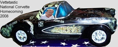
From: Larry Richter, Founding Treasurer of SACC:
Hi Regarding the Paint type. All
Corvette's were painted with lacquer through the 1981 model year, if built in
St. Louis. The ones built in Bowling Green did use a base-clear coat paint for
the 1981 Cars. To be factory correct no clear coat should be applied to the
car. Enjoy your 58. Thanks Larry Richter
**********
Hi, I'm working on a 1960 corvette for a customer. Im woundering where the
data plate location is at. Im looking for paint code number and any other
information it might have. Was told might be under dash pass side by heater
valve. Thanks for any information. Lanr
From:
Bill Huffman, Michigan Chapter President:
Lane,
The short answer to your question is that there is no paint data plate on any
1953-1962 Corvette.
Depending on the build date, the VIN plate will either be just below the
driver side upper door hinge attached with Phillips head screws up thru approx
mid Nov 1959 or resistance welded to the top surface of the steering column
just forward of the firewall.
You may find crayon markings that give an indication of paint color on
the panel behind the passenger seat or in the trunk front panel behind the
trunk liner cardboard.
Good luck with your project,
Bill Huffman, Pres.
Michigan Chapter SACC
From: Chip
Werstein, SoCal Chapter Advisor:
Lanr,
There are no data plates on Corvettes prior to 1963. The original color may be
found written in green crayon behind the cardboard trunk divider once the
paint is scrapped away. It is usually on the right side. It will only tell you
the primary color, not the cove or interior color. The interior color can
usually be determined by examining the interior of the car for signs of
original interior paint. Under the speedometer housing is usually a good spot
to look for original interior color.
From:
Max Brockhouse, SACC President:
The only paint indication on a 1960 Corvette will be in green crayon. This
will be located in the trunk. Remove the cardboard on the bulk head. Look
between the center support and the right hand spring tower. If there is still
paint , take a coin and press firm until paint chips or flakes off. Once you
find a green spot, go slightly right, left, down and up until letters begin to
form. The green crayon is wax and paint will not stick, allowing the paint to
flake off. That is why you do not want to grind or scratch vigorously. This
will only destroy it for ever. I would suggest you apply clear on top of the
color area once you find it to save it for another 50 years. It will be
written in a slight upward angle. Long paint names will be shorten. For
example, BLk for black and BLUE for silverblue. Good luck and let us know
what you find. The 1960 may not have left St. Louis painted silverblue.
Max Brockhouse SACC President
**********
Hello
Thank you for taking time to help. I have recently started restoring my 54
corvette and when I went to remove the gas tank, I noticed that it had been
leaking and when I got the tank out, I can see that it had been externally
patched in three places and coated internally with sealer. I think that it is
time to replace the tank. In searching the catalog parts companies, I could not
locate anyone who actually sold a reproduction 54 gas tank. Is there anyone
that you could recommend that sells reproduction tanks or should I go to a local
company in the area that claims to repairs gas tanks? Although 98% of the car
is and will be original, I am not concerned with regards to the authenticity of
the gas tank so a reproduction tank is not an issue for me.
Any guidance you can give would be greatly appreciated.
Thanks for your time!!
Daren
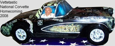 From:
Noland Adams, Founding President of SACC:
From:
Noland Adams, Founding President of SACC:
Daren,
I have had too much trouble with
rotted out gas tanks in the past. First, I tried an external patch, which worked
a few days. Next, I removed the tank, rinsed it out, and poured in a yellow goop
that was supposed to be an internal sealer. After sloshing it around to cover
the interior, you drain out the excess and let it dry for a day or two. That was
a BIG hassle, and it only worked a few days before it failed too. Finally I
found a brand new gas tank (expensive) and the problem went away.
In my opinion, the old tank is
nothing but scrap metal. I found a company that can get you a stainless steel
replacement gas tank for your 1954 Corvette. It is a little bit different in
shape, but it is supposed to fit and function properly. You can call them at
530) 677-4270 Pacific time. I hope this works okay for you.
Good Luck. Noland Adams
**********
Hi!
Can anyone tell me how the 4.56 rear end gears performed on the 62 Corvette.
Off the line performance and highway driving??
Thanks!
Rich
From:
Bill Huffman, Michigan Chapter President:
Rich,
Are you building a dragster or a driver ? Stock engine or GM Performance
engine ?
A 4.56 will give you fast starts & acceleration but also high RPM and high
ambient noise level at driving speeds. So, if you will be trying to drive
this car, it is not advisable.
I had a '62 with a 3.08 with a worn engine and had to slip the clutch to get
it rolling.
After rebuilding the 327-250 HP and adding a 327-350 HP cam, it ran well from
a standing start
& at highway speeds but it never was mistaken as a dragster.
There is a reason GM had 3.70 as the standard Corvette axle ratio until the
higher horsepower
327 came out in 1962.
Good luck with your project,
Bill Huffman, Pres.
Michigan Chapter SACC
From: Doug Prince, SoCal
Chapter Advisor:
4:56 gears are strictly for drag racing and are/would be border
line ridiculous for driving on the street. The 327 engine produced more rear
wheel torque than the 283 generation did and would be just fine with either
3:55 of 3:70 gears. You will never pass a gas station with the
4:56s!!!
**********
Hi,
I have 54 the post for the windows do not go all way down
so I can not lock them in, one of the knobs is bent where would I get the parts
to repair it and how hard is it to remove the door panel to replace it?
Thanks,
Bob
From:
Bruce Fuhrman, SACC Secretary:
Hi Bob,
The good news is the door panels and white metal bar are very easy to
remove, simply bring a Phillips screwdriver. The other good news is there are
no window wind mechanisms to deal with. The white plastic nobs and the chrome
bezel are readily available (see below). The locking mechanism may be a
challenge to find if broken. I am not sure why it will not engage. Do the
front first then the rear should drop in the hole in the chrome. Is the chrome
aligned properly? Did you replace / rebuild the side curtains and misalign the
square pins? Also, try sliding the white ball as you try to engage the pin.
Hope this works.
Bruce Fuhrman
Options for '53-'55 parts;
Grossmueller's 908-213-8832 (In Phillipsburg, NJ)
From:
Noland Adams, Founding President of SACC:
Bob,
1953 to 1955
Corvette side curtains (windows) is a complex combination of plastic, rubber,
and different metal alloys with many specialized fasteners (rivets, screws,
Etc.). Look in the member ads in our club magazine ON SOLID GROUND
for Steve Newsom. He rebuilds and restores side curtains to a like-new
condition. He’s in Texas at 281) 413-0028.
Regards, Noland Adams
**********
hi
I have 62 corvette , has 180 thermostat gauge showing 200 plus
thank you
Ray
From:
Bill Huffman, Michigan Chapter President:
Ray,
In no particular order, possible root causes are:
Radiator/engine block needs flushing,
Inadequate cooling level,
Improper anti-freeze vs water coolant mix,
Oil level low,
Defective or too hot thermostat,
Defective temp sending unit,
Defective temp gauge,
Defective fan clutch,
Defective water pump / blocked hoses,
Fan belt too loose.
First thing I would do is check fluid levels. other items
Then, have the actual temperature checked against the gauge reading.
If the gauge is right, check off the other items one by one, easiest to
hardest, till you find the problem.
Good luck with your project,
Bill Huffman, Pres.
Michigan Chapter SACC
From: Doug Prince, SoCal
Chapter Advisor: If you have
recently had the sending unit in the intake manifold replaced the current ones
sold at most auto parts stores are not calibrated to our C1 temperature
gauges. I very reliable investment is to purchase a digital infrared heat
gun. This instrument will give you a very reliable temperature reading to
know if you really have a problem. If you find out that the car does not
overheat but has an incorrect sender then you can go to any Radio Shack outlet
and purchase a very inexpensive diode to be placed in line with your blue
temperature gauge wire line and the sender.
From: Larry Pearson, SACC Advisor:
I have two 62's. One is 360hp and is all original including the sender, fan
clutch, 170 thermostat (replaced with new Delco), water pump (rebuilt), and
original 62B dated aluminum radiator (never has leaked yet). I bought this
car in 1972 and it never overheats.
I bought a second '62 360hp in 1974 and it came with the original sender, a GM
service replacement water pump, a 5-blade flex fan, 170 thermostat, and a
replacement hand-crafted cross-flow copper radiator. The FI has been replaced
with an AFB 340hp setup. The engine short block has been replaced with a GM
service replacement unit for this application (bought in 1974) and uses the
30-30 camshaft. It always ran over 180 degrees. No matter
what I did, it always ran hot. Then I read some articles by the De Witt
Corvette Radiators people explaining that the way the original aluminum
radiators were constructed, they cool much better (30%) than any copper
service replacement radiator can be made to cool. Even though copper conducts
heat (and electricity) much better than aluminum does. In the 70's I bought a
GM service replacement aluminum radiator to use in the FI car when the
original aluminum radiator finally failed, and I still had it in storage in
the garage. So I decided to put it in this car to verify that De Witt's
claims were true. They are! End of the overheating problem.
Some additional things to consider. Today's service replacement fan clutches
are calibrated to engage at 195 degrees, not 170 degrees. They can be
modified to engage at a lower temperature. Years ago an article was written
in the NCRS Restorer magazine on how to do this. These cars all came with a
170 degree thermostat, not 180. The 170 thermostats may still be available.
I have no ideas on getting a properly calibrated service replacement sender
unit. It is important that the fan shroud be completely in place. Make
certain that the fan blade tips are spaced out from the engine so they are
just inside the fan shroud. If you are using a fixed fan in place of the
clutch fan it has to be properly spaced out from the water pump to achieve
this. On the 340 and 360hp cars there are flat rubber seals on each side of
the radiator to prevent cooling air from bypassing the radiator on the sides.
There are also three flat rubber seals below the radiator glued to the
fiberglass to seal the bottom of the radiator. Consult the AIM to see how
this is done. Corvette Central should be able to supply the seals and special
retainers for the side seals. The engine timing must be set correctly (8
degrees, as I recall). I use Podell's lead addative to prevent detonation in
this engine (11.25:1 compression).
If you fix all of these things, you should have no more cooling problems.
Larry Pearson
**********
Do you have any info about how many 1960 corvettes Tasco Turquoise had silver
coves? I have #100.
From: Chip Werstein,
SoCal Chapter Advisor:
According to all the information I have from original Chevrolet documents to
current NCRS judging guides, the only cove color available from the factory on
a turquoise 1960 was white. 383 were painted turquoise with white coves.
However, note that 15 cars were painted "unknown special colors or primer".
We can assume that a dealer could and would paint the cove any color the
costumer requested. In my opinion, it is unlikely your car came from the
factory with a silver cove.
**********
Dear SACC,
I think I got a good one that may not have been seen
before!
I have my 58 trunk lid shimmed so the back and front of
trunk lid is even with body line. But both sides is 1/4 to 1/3 inch above the
body line. I believe the correct way to fix is to break loose the body
rear upper surround and shim up and fit to the trunk lid or maybe install new
upper rear surround.
Question: Can I do the opposite: alter the shape of the
trunk lid with to match the body line? Can I add new fiberglass material
to the trunk lid and then grind or cut off the old material on the sides of the
trunk lid?
Is this possible?
Aloha,
Eric
From:
Bill Huffman, Michigan Chapter President:
Eric,
None of these cars was perfect coming off the production line.
Over-restoring an old Corvette is like scrubbing a rare coin to "brighten" it
up.
Before you do anything, study as many other '58 cars as you can so that you
know what "normal" looks like.
The reason for shimming is to allow the weather-seal to keep water out of the
trunk area.
My advise............
If your trunk is wet, re-shim it.
If your trunk is dry, leave it be.
Good luck with your project,
Bill Huffman, Pres.
Michigan Chapter SACC
**********
I’m thinking of using Shell diesel oil 10-40 w
in my 1962 corvette with a 327 engine. (?) Dennis
From: Doug Prince, SoCal
Chapter Advisor: Many
controversies about today’s oils and older cars with flat tappet camshafts.
Starting about six years ago many engine builders were confronted with rebuilt
flat tappet engines with the camshaft going flat at or near break in. The one
thing we now know is that current engine oils do not have very much if any zinc
dithiophosfate or phosphorus. These compounds were very prevalent in the “old
Days” but the oil companies began to remove them from their oils because they
were not compatible with catalytic convertors in newer car exhaust systems. The
EPA has required auto manufacturers to warrant the catalytic convertors for
150,000 miles and the manufacturers went to the oil companies and made them
produce engine oils that would not devoid the warranty. Many specialty oil
companies have moved into the void and sell and produce oils with high zinc and
phosphorus compounds in them specifically marketed to our older cars with flat
tappet camshafts. Amsoil is just one of many oil companies that produce this
type of oil today. It is called Z-ROD and is a fully synthetic oil with high
concentrations of zinc and phosphorus. The downside of these specialty
compounded oils is they are not cheap but neither is your older Corvette. These
specialty oils are an insurance policy for your older Corvette engines.
**********
Do they make an insert to place in the convertible top bin on my 1957
Corvette. All I have is the hard top and I want to clean up the soft top
storage area.
Also does anyone produce the plug covers for the (2) holes in the bottom of
the above top storage bin?
Thanks
Bob
From:
Bill Huffman, Michigan Chapter President:
Bob,
The two holes in the bottom of the folding top storage area are drain holes
for water leakage,
so mine are left open.
In folding top equipped cars, there is a black felt pad glued to the tank
cover.
You could add a "big tank" cover to fill up the space or just use it as extra
trunk space.
This area is not readily visible if you have a hardtop only car.
Bill Huffman, Pres.
Michigan Chapter SACC
From Chip Werstein,
SoCal Chapter Advisor:
Bob,
I have 2 57's in my garage. One is an early car, the other is late. Each has
3 holes in the bottom of the convertible top storage area. I believe the
center hole, about 3/8" is a drain hole just in case water should get in the
storage area. The other 2 holes which are 2" in diameter and located just
under the hinges, are access holes for installing the nuts on the top of the
shock absorbers. Although I have never seen covers over those 2" holes, I
believe originally they would have been covered. I cut out 2 square pieces
of tar paper and glue them over the holes.
Chip Werstein
**********
Helping a friend restore a '59 Corvette. It is in pretty bad shape with a lot
of monkeys playing around the car for years. The front emblem is on and cut
through the Fiberglas. The rear emblem is missing and it looks and feels like
someone did a lot of body work. Did the rear trunk emblem fit through a hole
like the front emblem? Was it just put on with bolts through the Fiberglas?
How can we find the correct position of the emblem on the trunk? I would
appreciate any help you can give us.
Best regards,\Bryce
From:
Brad Bean, SACC Vice President:
Emblems in the front and back were
the same and fit the same on 58 - 60.
Yes, the front and back emblems were
mounted in the same fashion. The convex "bowl" of the emblem fit in to the
larger hole with the three studs fitting into the three smaller holes on the
body/trunk lid. The three studs are fastened with speed nuts.
From:
Bill Huffman, Michigan Chapter President:
Bryce,
58-60 have hole in the front panel for the front emblem. They would have the
same size hole in the trunk lid for the rear emblem. They use the same emblem
front & rear and they attach with 3 speed nuts onto the 3 bezel studs.
If the trunk lid on your friend's 59 has no emblem hole, it may be a 56-57
trunk lid or one of the previous owners glassed or used body filler to close
it.
Either way, there are two choices.
Buy a correct trunk lid w/ emblem hole or find a correct 59-60 to use to make
a locator template.
A 58 car would work but the trunk spears would make the template more
difficult to accurately locate for a 59.
Good luck with your project,
Bill Huffman, Pres.
Michigan Chapter SACC
**********
I have a 1961 245HP duel wcfb carbs. It stalls on left hand
turns only. I first thought it was vapor locking but temp from carb bowls to
fuel pump is good. I tried using racing insulation on fuel line from fuel pump
to fuel bowl/filter to be sure. I checked the rubber fuel line from steel line
to fuel pump, no problem with clearance or twisting or binding due to torque.
Replaced fuel pump which seemed to have helped, but still have the stumble.
Do you think it is the Carter part number 145-142 brass
bushing between the fuel bowl and the vacuum passage.
Out of ideas in N.C.
Chuck
From:
Doug Prince, SoCal Chapter Adviser:
Stalling while only turning in one
direction usually indicates that some of the floats are not set properly
allowing fuel to slosh from one or more vent tubes. The beauty of Rochester
fuel injection is that it eliminated this problem! Check and reset your float
heights to factory specifications.
**********
Hi,
I'm not a member but I came across your website and I have a question I'm
hoping you can answer. I have owned two Corvettes many years ago. My first was a
1959 that I bought in 1964 and the second was a 66 I bought in 1985. Hands down
my 59 was the car that gave me Corvette Fever.
I'm a little older now and have started a build on a new Morrison 62 solid
axle chassis and not being able to find a 62 body that I could afford I opted
for a Downs Industries replica 62. Unfortunately it is as hard a build as if I
had bought a 62 wreck. Nothing fits, everything has to be customized to accept
NOS or original parts. (I'm referring to the body, the chassis is perfect.). Now
my question; Do the cut outs in the floor pan beneath the fuel tank have a
purpose? The floor in my replica is solid. No holes. Someone on another forum
suggested that the original cutouts were a safety feature and that has caused me
some concern. Can you clarify this issue for me?
Thank you
Bob
From: Doug Prince, SoCal
Chapter Advisor: You should probably contact Morrison first since they got
you into this “mess” in the first place. We are predominately a factory
original organization with little or nothing to do with “kit cars.” Good luck
with your project…….
From:
Bill Huffman, Michigan Chapter President:
Bob,
Although I don't disagree with Doug regarding kit cars, as a
retired automotive engineer, I believe you have asked a safety related question
that might be of interest to C-1 owners.
The holes below the fuel tank have three purposes;
1) Drain plug clearance hole on the far right (pass) side to allow the tank
to be drained while
still installed in the car.
2) Holes for front attachment of tank hold-down straps& attachment brackets
to secure the
tank in place. It is extremely important to use both the straps and the
insulator
between tank & straps to eliminate metal to metal contact.
Loose tanks, wear / abrasion & possible sparking are not good.
3) Other holes are to allow circulation of air up & around the tank.
Without these holes, gasoline vapors could leak into the passenger
compartment.
Other holes that may be missing are the tank vent hose holes that should be
located in the gas filler area. The gas tank must be vented.
In the long run, my bet is that it may be less expensive to buy a new body
from these folks,
Back to the Future Products, LLC.
In any case,
Good luck with your project,
Bill Huffman, Pres.
Michigan Chapter SACC
**********
My 59 is an early car. Our research after buying a judging guide says the
inside of the trunk should be interior color. My car will be black with red
interior. So is the underside of the trunk lid red? Thanks for your help.
From:
Brad Bean, SACC Vice President:
Trunk compartment color has
frequently been a point of discussion, as different examples exist.
Noland Adams' Corvette Restoration &
Technical Guide, Volume 1 (pages 254 & 255) indicates that for 1958 throught 60
the trunk compartment color matches the car's interior. He goes on to say the
1958 Corvette paint instructions indicate the hardtop, trunk compartment, deck
lid panel (inside), and folding top lid panel (inside) were all painted the
same; to match the car's interior. He states the factory continued to use these
same painting instructions for1959 and 1960.
He also cites an example of a 1960
Corvette where a trunk compartment was painted the same as the car's exterior.
He only indicates this for 1960 and states there is no rhyme nor reason as to
the timing or why it occurred.
However, the NCRS judging manual (
page 12) states: "1958 and early 1959 trunks were painted interior color.
Remainder of 1959 to 1960 painted exterior body color."
You mention your Corvette is an early
59. If so, both opinions support painting the trunk interior the same as the
car's interior color. Nolans research supports the inside of the deck lid being
the same as the trunk color. There is a GM file photograph of this on an early
1958 prototype, on page 242 of his book.
**********
Hi,
I have a 1954 corvette will a 1953 fuel pump work in my car? Also you help me
last week on the carb’s flooding all three were flooding, what should the
pressure be from the pump?
Thanks,
Bob
From:
Bruce Fuhrman, SACC Secretary:
H Bob,
The '53 fuel pump (AC 9797) is the same as the passenger car pump and
easier to find. It will work on the '54 except you will not be able to locate
the fuel filter by the pump where it was placed on the '54's. The '53 filter
was mounted in front of the #1 carb. The '54 pump (AC 4132) has the fuel
attachment lines angled to permit the filter to be added next to the pump.
The fuel pumps produce about 10 psi. I put a pressure regulator in mine and
set at 1.5 psi and I works fine, no flooding. You may have needle valve seats
that are worn or accelerator pump diaphragms that are porous causing the
flooding?
Good luck,
Bruce Fuhrman
**********
Hi Everyone.
I have been trying to find out the correct ppg code in lacquer paint
for for my 1954.The new tech manual and judging guide only says Metallic Beige
for the interior pieces the car is Pennant blue. Does any one know the exact
code in lacquer they used.for the Metallic Beige.Thank you Bob
From:
Bruce Fuhrman, SACC Secretary:
Hi Bob,
If there were codes in 1954, I do not know where they recorded them! Maybe
Noland knows. When I restored my '54 we were able to find some protected
original paint under the weather striping and some metal plates. We polished
and clear coated the best spot and the painter computer color matched to the
original color perfectly. There were only 300 painted Pennant Blue.
Good luck.
Bruce Fuhrman
**********
I have another question, where on
the frame are the vin numbers on the frame. Rick
From:
Bruce Fuhrman, SACC Secretary: The stamped VIN
# is stamped on the top of the frame rail on the left side about under the
drivers thigh. It cannot be seen since there is only about a one inch gap
between the Fiberglas floor and the frame. To check it, I had to make a thin
wood stick,wrap it with sandpaper, then clean off many years of dirt and rust.
Then clean off, pack in some white chalk or powder, then blow off. Then use a
small dental mirror and flashlight to read the # and compare with the door post.
They should match.
**********
Hi
I have a 57 Vette. The door was not closing properly. I tried to adjust the door
striker. Two of the 3 screws were stuck solid and impossible to loosen. I tried
PB blaster, using an impact screwdriver, and finally I've drilled out the heads
figuring I could get it with a stub remover. Still not working. I think a prior
owner has glued the sticker bolts. Is there a way to access the bolts from the
back side? What do you suggest.
Thanks, Bob
From: Doug Prince, SoCal
Chapter Advisor: The door striker bolts screw into a nut plate that is
behind the door jam and is basically not accessible unless you want to remove
the wheels and cut through the body. The screws have become completely rusted
over time and this is not an uncommon problem with C1s. I suggest that you
grind off the remaining heads and drill out the screws and install helicoils to
repair the holes in the nut plate itself. Be patient and good luck with this
project.
**********
Hi,
I just pick up a 1954 corvette a few issues: the first is when I start the car
gas pours out of the carb’s and the engine starts shaking, and the top it came
shipped down how do I put it up what is the process?
Thank You,
Bob
From:
Bruce Furhman, SACC Secretary:
HI Bob,
The gas coming out of the 3 carbs is either bad accelerator diaphragms
(rubber which gets attacked by our new gas) and / or stuck needle valves in
the float chambers. You need to rebuild the carbs and put a pressure regulator
in line and set for about 2 psi.
I am not sure what top you are referring to? The convertible top, hood or
the top of the carbs?
Bruce Fuhrman
Follow up: Thanks for the tip on the carb’s . The convertible top, having a
hard time latching the rear to the deck is there a procedure do I start latching
front middle bows or rear first? Thanks,Bob
From: Bruce Furhman, SACC Secretary: Hi Bob,
OK, this is a common problem with '53 - '55 tops. Here is what I did to keep
them latched assuming you want to keep all stock.
The back plates in the deck cover are probably worn and are made of soft metal.
Any vibration and they pop loose. So, latch them first, then the front. I
replaced the 2 plates which helped but did not keep them from coming loose on
long trips. I then wedged a small piece of rubber between the chrome release
lever and the base clip which keeps the teeth engaged in the base plate. You may
want to place a rubber band or duct tape around the rubber and lever to assure
it does not come out. This has worked for me on long trips.
Good luck.
Bruce Fuhrman
**********
I was driving my 62 original 327/300 hp about 60 mph, in the cool evening,
when the engine just shuts down as if you would turn the ignition switch off. It
was off for about 10 seconds then the engine restarts and continuous to run. Ok,
odd...drove for another 2 or 3 minutes then off again. This time after I came to
a stop on the side of the road.... She would not start. Towed her home and look
for electrical problem because it had gas going in the carb when I would pull
back the throttle lever. Changed out the coil and she started right up. Great!!!
When sitting behind the wheel it is automatic to look at each gauge for those
whom have had one for decades. Well, the battery was on constant
discharge...not much...but it wasn't where it should have been. More especially
when I would reive the engine it may move a fraction but would remain in the
negative side. Turned on the lights still no movement. Thus, I changed out the
volt regular, coil resistor still the same. Your suggestion and/or experience
on what I may do next would be much appreciated.
Thanks
3208
From:
Max Brockhouse, SACC President: Generator or
regulator and most likely the coil voltage resistor problem, but I am not sure
which. At a recent antique tractor meeting (club that I am involved with) a
battery shop spoke and he says always check the battery first. If a battery is
3 years old it most likely has failed and sometimes it will not hold enough for
a generator to keep up allowing for no spark to the engine.
Max Brockhouse SACC President
From:
Bill Huffman, Michigan Chapter President:
Darrell,
Sounds like you had a defective ignition coil.
The voltage regulator that you replaced may not have been defective.
I would advise you to polarize the electrical system.
Form a 4-5 inch insulated copper wire into a C-shape and arc across the
Battery & Generator (top & bottom) terminals on the voltage regulator.
There is no way to know how long this condition has existed so be sure to
have the battery & generator output checked after you get it running.
Good luck,
Bill Huffman, Pres. Michigan Chapter SACC
**********
Simple question: how to install gasline/brake frameclips on 57. I push them in
the holes and they are still loose. The ends going through the frame rails are
crescent shaped and do not spring back. Whats the secret?
Thanks,
Bob
From: Chip Werstein,
SoCal Chapter Advisor:
Bob,
The reproduction brake/fuel line clips sold by the various Corvette suppliers
simply do not function as they should. I always buy extras because I know some
will break and others will fail. Any tension on the fuel and brake lines will
pull the clips out of the frame. Make sure your lines are straight and
true.............not always an easy thing to do.
**********
I am restoring a 1959 corvette
Black, silver coves and red interior. I have done research on the paint code for
the red dash color and have found several different answers. I was hoping you
could answer this question for me as we are at the point of needing to buy the
red paint. We meet your club in Kissimmee Fl, Very nice group hope to meet again
as we have two C1 corvettes and LOVE them. Thanks hope you can help me out with
this question. Debbie
From: Doug Prince, SoCal
Chapter Advisor: The red interior color of your 1959 Corvette was called
Roman Red. There were three different manufacturers of this lacquer color from
St. Louis. DuPont 2931LH, R&M A1138R and Ditzler DDL70961. Lacquer paint is
generally not available today but a high quality body and paint shop should be
able mix up this color for you using modern paints and materials.
**********
good afternoon. My name is Don and I live in Ohio. Is there a local chapter
or can I register otherwise? I do have a question about 57-62 positraction
carriers. I am currently restoring my 62 that I have had since 1966. I have
heard that there are two or three generations of carriers and I would like to
know how to identify them so I can get the correct parts and also clutch packs.
If there are sources for parts that you know about, that would be helpful also.
Thanks, Don
From:
Bill Huffman, Michigan Chapter President:
Don,
Unfortunately, there is not currently a local SACC chapter in the Ohio area
but all it takes is a few interested C-1 owners to start one. You didn't say
where you live in Ohio but after you join the National SACC, Michigan Chapter is
authorized to admit members from NW Ohio & NE Indiana.
Contact me at
MI_SACC@yahoo.com if you are interested.
Regarding rebuilding a posi unit, I assume from your question that your car
does not currently have a posi-traction differential. But whether that's true or
not, contact Darrell Shepherd at 4 speeds by Darrell in Vermilion, IL.
He can rebuild your differential or sell you a correctly dated posi-traction
unit. Darrell has rebuilt two 3.70 posi units for me. I supplied the
correct castings & flanges.
He supplied the GM series 3 carriers and other internal components.
Good luck with your project,
Bill Huffman, Pres.
Michigan Chapter SACC
**********
My 59 vette ,283 with carter wcfb
4bb starts good when cold. After driven half hour or more, fully warmed
up, and shut off and restarted within 1 to about 2 minutes will starts
good but if not started for 10 to 20 minutes it won't start unless I
press the gas peddle to the floor. It acts like its flooded. I removed
the air cleaner and can see an occasional dripping of gas in the
manifold. Carburator has been rebuilt. Timing, point gap all good. Been
told it's todays lousy gas. A friends 57 chevy 283 does the same thing.
Hope someone has a solution as this is hard on starters. How do I join
your organization? You help a lot of people. Thank you very much.
From:
Bill Huffman, Michigan Chapter President:
Joining is easy.
Look for the membership application tab just above the technical help tab.
Print it, fill it out & send it in.
If you live within the borders of an SACC Chapter, you should give then a
try also.
Your car has a common issue that has been discussed previously
Basically, your '59 and your friend's '57 have the same cast iron intake
manifold (3746829) with built in carburetor heating ports. The hot start
problem is from the fuel boiling over into the carburetor throat and into the
engine.
In order of difficulty:
1) Switch to premium gas which has a higher boiling temp.
2) Set the float level lower but not so low that it cavitates on hard
turns.
3) Put extra gaskets or a fiber spacer between the manifold & carburetor
as a heat insulator.
4) Switch to the fuel injection intake manifold gasket set that closes
off the carburetor heating ports
.
Good luck solving your flooding,
Bill Huffman, Pres.
Michigan Chapter SACC
**********
Hello, My name is Mike and l own a 1960 Corvette. I would like to go to a
larger wheel and tire combo in the rear. I currently have a 6.70/15 stock
tire on stock wheels. I would like to upgrade to a 7 inch tread width
tire. What backspacing is needed on the wheel to fit this size tire
without modifications to the body or suspension?
Thank you,
Mike
From:
Bill Huffman, Michigan Chapter President:
Mike,
You can put Coker American Classic 205-75R15 tires on your stock rims all the
way around to get wider tires, radial performance and a stock appearance all in
the same package w/o affecting your speedometer. That's what I would recommend.
Bill Huffman, Pres.
Michigan Chapter SACC
**********
Hi, My name is Bob . I have a 1960 Honduras maroon corvette that I've owned
since 1975. It's mostly stock original except for some updates, tires carb,
intake, electronic distrubuter,etc. If you attended Memphis it was there! My
question and problem is, I have stock wheels and original hubcaps not after
markets. The hubcaps are a real bear to mount on the wheels Is there any trick
or method to making this job any less of a strain . I've spent hours taking the
dents out and then only putting them back in when I install them. IF
this e-mail thing works out I have many questions about my car. serial #9953
out of 10261 found a lot of 61 parts on the car that look like they were there
from day one! THANKS BOB
From:
Bill Huffman, Michigan Chapter President:
Bob,
I saw you and your car in Memphis. I remembered it because I have one just
like it.
Regarding the wheel covers, I have a 2 1/2 inch diameter rubber hammer and a
1 1/2 inch vinyl lead shot filled hammer that I use depending on how tight the
rim to wheel cover fit is.
-I have never dented mine but I sometime have to tap around the outside edge
2 or 3 times to
make sure the cover is completely seated.
Always strike the cover squarely with the face of the hammer, never with the
edge.
A piece of 2x4 to use as a tapping block might help in keeping the hammer away
from the cover.
Bill Huffman, Pres. Michigan Chapter SACC
**********
I am a new member and have a 1962 corvette 4 spd. I do not
know if it was the original transmission. I took it to the shop that has been
working on the car because I lost a screw in the shifter and could not get the
car out of reverse. The screw was installed, but the car now runs much less
smooth, and vibrates more than it did previously. I thought that the shifter
made need adjustment and took it back to the shop. They said that the
adjustment was fine( the car shifts from one gear to another easily) but they
noticed a jury rigged transmission mount that may be creating the problem. I
order the correct transmission mount. They also noticed that the shaft on the
drive shaft yoke was exposed to a greater length than it should be. They thought
the trans may have been converted from a 3 speed and said that I need a new
drive shaft, which I presume is longer than the one on the car
My questions are( 1) how much of the yoke shaft should be
visible and (2) Are there different drive shaft lengths for a 4speed, a 3 speed
and automatic trans( in case the car was initially an automatic trans).
From:
Bill Huffman, Michigan Chapter President:
New member,
Sounds like you may have a number of underlying issues that may need to be
addressed.
Questions:
Stock shifter with reverse lock-out? Does it have the anti-rattle spring &
bracket ?
Is the car really vibrating or is it the shifter? Or the drive shaft/ yoke ?
The 4 -speed transmission mount is different than a 3-speed mount although
the transmission cross-member/support is the same.
If the transmission was misaligned, the spline on the output shaft or the
drive shaft yoke spline could be loose/worn. On a '62, you should have the 26
tooth spline on shaft & yoke.
Regarding yoke exposure, you most likely saw 1 to 1 1/2 inch of exposed
outside diameter due to rear suspension drop from being up on a hoist.
Good luck with your project,
Bill Huffman, Pres.
Michigan Chapter SACC
**********
Thank you for the earlier prompt reply's to several question I have sent to
your relating to my 1960 C-1.
My primary issue with this car is that at 65 or 70 mph, my engine, with the
3.7 rear end is turning over 3,000 rpms. If I go to a 3.08 posi this should
drop my rpms down to around 2,600 or so.
I have owned this 1960, two 1969's, a 1999 and a 2007. Both the 1999 and 2007
were 6 speed manual transmissions and at 70 mph the engine rpms were barely
over 1,600. What do you have to do to this car to get the rpms down to around
2,000 at 70 mph?
Season Greeting to You and Yours,
Don
From: Doug Prince, SoCal
Chapter Advisor: It may be a
case of wanting your cake and eating it too! Remember you are driving a C1
Corvette and not a C5 or C6. Six speed manuals are great today but your C1 is
54 years old. Depending on what engine is currently in your C1 going to 3:08s
will make it a real dog around town. Based on my experience, I suggest that you
may have to get used to the RPMs.
*********
I have a Roman Red 1959 with white coves, white soft-top, and black interior.
I would like to add a hardtop which was originally part of the build, but no
longer in my possession. What is most proper, a white hard-top or red? I
prefer the red, but can live with white if that is more correct. Thanks!
From:
Bill Huffman, Michigan Chapter President:
Most hardtops that I have seen are body color although there have been a few
painted the cove color.
What is proper? Or were they even available in cove color from St. Louis?
I didn't work there, but I know a couple of guys who did.
They are blind copied on this memo so perhaps they can tell us .
Bill Huffman, Pres.
Michigan Chapter SACC
From: John Hinckley, Michigan Chapter Advisor:
Factory-installed hardtops left St. Louis in body color; there was no
mechanism to order them any other way.
Regards,
John Hinckley
From: Brad Bean, SACC VP:
Never say never, but
hard tops were only offered, from the factory, painted the primary body color.
I am aware of one case
where it was painted to match the cove, at the dealer prior to delivery, which
I guess would have made it "original".
Also, the headliner
color and style should match the car's interior color and year.
Personal note... for
investment purposes, it's nice to have a correct hard top, for a car which
came with one. I too purchased and restored one for my '60. However, I enjoy
driving the car with the top down and it was a pain taking a hard top of it
on. Plus, if I left home with the hard top on, no matter how nice the day was,
the hard top had to remain on until I returned home. After one summer of
using the hardtop, I stored it in the garage where it remained for 15 years;
selling it rather than move it following retirement.
Just food for thought.
**********
I have recently purchased a 1960 Corvette that has had a frame off
restoration. Since the restoration the bumper "down" nose panel has been
damaged. I have located a replacement part from Zip Corvette parts.
My question is how much of the old nose down panel has to be removed in
the area where it bonds to the nose "up" panel?
I have recently acquired several books on automotive fiberglass repairs and
intend to install this part myself.
Any other guidance would be appreciated.
From:
Bill Huffman, Michigan Chapter President:
Ron,
The lower front panel as an OEM part extends from the center line of the
headlights back to the wheel openings from one side to the other behind the
bumpers and below the grill surround. You might want to consult a local Chevy
dealer or body shop that does fiberglass repair to see if your lower panel can
be repaired. An otherwise completely restored C-1 is a poor place to start
learning fiberglass repair.
Remember the Hippocratic Oath, "Do your patient no harm".
Or as Dirty Harry says, "A man has to know his limitations".
Bill Huffman, Pres.
Michigan Chapter SACC
**********
Follow up question, I have owned both a 1999 and 2007 Corvette and both had
the 6 speed transmission.
My goal on this car is to make it as drive able as possible yet maintaining
the external appearance of being 100% original. Do you know if it is possible
to install one of these transmissions in this car? I would like to get the
motor turning around 2100 rpm at 70 if at all possible. The 1999 and 2007 were
turning around 1600 with the six speed.
Thanks,
Don
From: Paul Lemieux,
Michigan Chapter:
My 59, 230 hp, had an original 3 speed, 3.70 geared drive line. The trans
started to leak quite a bit so a decision was made to replace it with a
keisler built tremec 5 speed. At 70, my engine is turning just 2100 rpm, this
has made the car so much more fun to drive. I also optioned to have the
optional shifter which is identical to the stock 4 speed shifter. I ordered
directly from keisler and had the trans professional installed, I believe that
Corvette Central also sells the keisler unit.
Paul
**********
Hi
I have just recently joined the club and my member number is 3701. I purchased
a 1960 C1 that has had a frame off restoration in 2009. I have been working
out of country and the car was not driven until I retired in August of this
year.
There are three primary issues:
Issue #1: The clutch pads are frozen and the limited slip feature of this
rear
end is not working. I have added one of the additives that
was
recommended, went to parking light did figure eights, and
pads are still stuck.
What is required to service these pads?
Issue #2: The car has either a
4:11 or
4:56 rear end and at 70 MPH the
tach is showing 3,000+ RPM.
I am getting parts estimates of between $ 1200 and $ 2400
to install a posi
3:36. Any idea as to which estimate is reasonably
correct? Is a
3:08 possible?
Issue #3: The car has a 383 stroker installed with an estimated HP of 450.
Since the car has the original tire size and I do not plan to spend
my weekends at the drag strip, I do not believe that the
chassis
or rear end will be at risk. Do you believe otherwise?
Donald
From:
Bill Huffman, Michigan Chapter President:
Don,
Let's address your questions one at a time.
1) I had a similar issue with a rebuilt 3.70 posi unit. I had it rebuilt,
then went a couple years before I got around to installing it. We put in Posi-lube
plus a GM additive and spent a couple hours doing figure 8s. The clutch pads
were still stuck.
Took the car on a 50 mile road trip, drained the axle lube completely,
added another bottle of GM additive and then tried the figure 8s again. over
the next week of short runs, the posi unit began working fine.
2) With a stock 3.70 axle in mine, it runs 3000-3500 RPM at highway speeds.
Since your car was recently redone, and if it has the original rear end,
you should be able to read the axle code stamped on the passenger side front
surface of the differential casting along with the differential assembly date.
Look for AN for 3.70, AP for 4.11 or AQ for 4.56.
Casting number on the driver side should be 3743833 along with a casting
date.
Last complete rebuild cost me about $1800, summer of 2012.
Either a 3.55, 3.36 or 3.08 will require a new carrier.
It is your car, make yourself happy.
3) The 1949 Chevrolet chassis with stock tires, brakes and steering in
your 1960 Corvette was never designed to handle 450 HP in any way except
CAREFULLY.
Good luck with your project,
Bill Huffman, Pres., Michigan Chapter SACC
**********
Hi,
My name is Jay and I am looking for the pins and clips that hold the shifter
to the trans. on a 1961 4 speed.
Thanks for your help,
Jay
From:
Bill Huffman, Michigan Chapter President:
Jay.
You don't say whether you have a Borg Warner T-10 or a Muncie Transmission. You
also didn't say whether you have a stock shifter or a Hurst.
. An OEM original 61 Corvette w/4-speed should have a BW T-10 with T-handle
reverse lock-out. However, after 52 years any combination is possible.
After you find out what is in your car, complete linkage kits for your
combination are available from most Corvette parts vendors for less than $100.
If you really only need the pins & clips, check Corvette Central P/Ns 531016
& 531115.
Bill Huffman, Pres. Michigan Chapter SACC
**********
Hi there, we have a 1958 Corvette with a 1962 283 engine
with an aluminium intake manifold. Can you tell us whether the 1962 283
corvette motor had an aluminium intake manifold from factory?
Regards,
Dave
From:
Doug Prince, SoCal Chapter Advisor:
All 1962 Corvettes were assembled
with the newly introduced 327 cubic inch engine with various horsepower
ratings. The 340 horsepower version had a single four barrel aluminum intake
manifold.
**********
Hello !
Trying to improve the turn signal cancel mechanism I got some information from
Rarecorvettes that refers to some leaf springs that go under the turn signal
ring. With the mechanism laid out in front of me, I see neither the thin leaf
springs, nor any place to mount them if I had 'em. Is there a source for these
internal steering column parts ?
Thanks,
Gary
From: Doug Prince, SoCal
Chapter Advisor: The turn
signal cancelling cams very often wear out. Paragon Reproductions sells a
complete turn signal cancelling cam mechanism , part number 8960K. Your turn
signal housing has two small wheels that must be cleaned and lubricated in order
for the new mechanism to work properly. Use needle nose pliers to insure that
they turn freely after cleaning and lubricating them.
**********
Hello. I have a question regarding starter motors for C1 Corvettes. I have a
1958 Corvette with the original 283 engine. I have tried to keep it mostly
original. I am trying to find out if anyone actually makes a high torque
starter motor that will fit my engine. It does not have to be a mini starter, a
full size starter will be fine. I have tired unsuccessfully twice in purchasing
a high torque mini starter only to find out it does not fit my engine. The holes
on the engine are 1/8" off from the holes on the starter. The reason I am
looking for a high torque versus a regular, is after I drive for about an hour
and the engine is hot,, when I stop for a coffee and return to start the car, it
is difficult to start. I have narrowed it down to the starter being overheated.
I added a thermal wrap to the motor/ solenoid, but that did not really help.
Or does anyone make a high quality starter that does not get overheated and will
start easily in warm weather. (it gets warm in Calif.)
Any ideas or assistance is greatly appreciated.
Thank you,
Tim
From: Doug Prince, SoCal
Chapter Tech Advisor: This one
is very easy. Just buy a GM starter for a big block Corvette C2 as all C2s with
the big engine had a high torque starter motor. You will have to just change
the end frame, the part that bolts to the starter in a C1 to the bell housing.
This is an easy fix and you will love the difference it makes. I also suggest
that you install a larger in diameter positive battery cable when you make this
conversion. Go to a two gauge or larger as they flow more current with much less
resistance to engine heat. Works like a charm for me.
****************************************************************************************************************
Hello there,
My dear husband who would kill me if he saw that I was typing this, misplaced
the only set of keys we have to our 1961 Corvette. I have a sneaking
suspicion they are in the trunk, but he seems to think they are in the pocket to
a USMC uniform that he turned back into the Corps when he retired last year.
Anyway - no locksmith wants to touch the car, so I thought I'd seek expert
advice about how I go about fixing this dilemma.
Any advice would be greatly appreciated.
Thank you,
Michelle
From:
Max Brockhouse, SACC President: The good news is, you can open the trunk
without a locksmith. The bad news is, you will have to damage the trunk
emblem in order to do it. Drill a series of holes in the plastic emblem to
weaken it and break it out as well as the metal dish behind the emblem.
Now use this hole to reach the rod on the key tumbler inside the trunk lid. Now
pull the rod until the latch releases. Good luck and all is not lost
.
From: Bruce
Fuhrman, SACC Secretary:
One way would be to remove the glove box key assembly and take to a locksmith.
He can make a key which if a stock car should match the trunk lock.
Phil, an owner of a '62.
From: Bill Herron, past Treasurer of SACC;
"One key fits all" on my 57. If your glove box
is unlocked, open it and remove the lock. The actual lock unit (inside
the housing) will have a four digit number stamped on it; that's the key code
for that lock. I don't recall 61 for sure but assuming it's the
same as 57 that code (and a competent locksmith) will be able to make a new
key. As an alternative, call AAA (I did once when I locked the keys in
my trunk 3500 mi from home!). I won't bother with the details but a
locksmith came out and opened the trunk with no damage.
Bill Herron
**********
Im looking for a place to purchase a service manual that has the information on
how to change and set up a new crown and pinion gear set.
Hope you can help.
Thanks
From: Doug Prince, SoCal Advisor: Refer
to Corvette Service Manual ST-12 Chapter 4.
**********
Hi,
Could you please supply me with the wheel alignment specs for my '61 Vette?
It's steering very average and I've got her booked in at the local tyre shop for
adjustment but they haven't any spec's.
Thanks in advance,
Alex
From: Doug Prince, SoCal Advisor:
As
per Corvette Service Manual ST-12 wheel alignment is as follows:
Caster
2 degrees +- ½ degree
Camber
½ degree +- ½ degree
King
Pin Inclination 3 1/2 to 4 1/2 degrees
Toe-In
(per wheel) 1/16th inch – 1/8thinch
Toe-Out
on Turns
Inner Wheel 20 degrees +- 2degrees
Outer
Wheel 24 degrees +- 2dgrees
**********
I've got another question.
I need a service manual / rebuild manual with pictures of the original
3-Speed Saginaw transmission which is used in my 1960 Corvette.
It seems that there is no information or manual about this 3-Speed
transmission. That is very disappointing. Furthermore there are no rebuild
kits for this kind of transmission available?
Do you know where I can gather information about this transmission or even a
book? And where to buy any correct rebuild kit?
Thank you very much and have a nice day.
Yours sincerely
Ruedi Keller, Switzerland
From: Doug Prince, SoCal Advisor: Information
about rebuilding and repairing three speed manual transmissions can be found in
a 1961 Chevrolet Passenger Car Shop Manual. The chapter in this manual
would also apply to your 1960 three speed transmission.
**********
I have a 1962 corvette and would like some help the number on the
steering colm is #20867S103393 I would like to know the build date of the
corvette and what would be the correct date code for the block and heads 327
340 hp with 4 speed any help would be great
Thanks Walt
From:
Max Brockhouse, President of SACC: Your '62 was built fairly early on the
15th of November1962. Actually your '62 is fairly early production model
year. The '62 started production on September 17, 1962.
**********
What type of gas should I use in my 1959 vette it's a 283 automatic just
restored,thank you Phil
From: Doug Prince, SoCal Advisor: Your engine has lower compression
than the high performance engines and should operate just fine on 91 Octane
gasoline. Today’s gasoline’s are 10% gasohol which is very detrimental
to older cars fuel systems. Gasohol attracts water which when combined
with alcohol forms an acid compound which will start to eat away at the inside
of older pot metal carburetors and metal fuel lines. By adding one once of
automatic transmission fluid to each gallon of gasoline will inhibit this
process so that rust and acids can not form in your Corvette’s fuel system.
**********
Hi,
I just ran across your web site and I'm not an SACC member. I have a 1960
Corvette and the generator has started to smoke so I'm guessing that it needs to
be rebuilt. Do you have any recommendations for a shop that can either rebuild
my current generator or a source where I can purchase a "new"
generator? I live in Minnesota but obviously I'd be willing to send the
generator off to a shop that knows what they are doing.
Thanks.
Doug
From:
Noland Adams, Founding President of SACC:
Doug,
When
replacing parts on your 1960 Corvette, be aware that original parts are more
valuable than common replacement parts. Even if your Corvette is modified, keep
any original parts you have.
Normally
generators are rebuildable if the case isn’t damaged. Every Corvette parts
dealer will have a shop in their area that rebuilds generators, starters,
distributors, master brake cylinders, Etc. If your part is original, be sure
that you get your original rebuilt and returned. I don’t know where you live,
but I’d contact the closest Corvette vendor first.
If
you can’t find a vendor, call Corvette Stop at 530) 677-4270. I have worked in
Drew’s business for several years, and he knows about the needs of Corvette
owners. Corvette Stop is in El Dorado County, California, just East of
Sacramento. That’s why I suggested that you try a local source first.
Enjoy
your “60,
Noland
Adams
From
Doug Prince, SoCal Chapter Advisor:
First off
there are many qualified generator rebuilding shops scattered across the country
but you must first determine that you have the correct generator that is
original/correct for your Corvette to go through the motions of having it
rebuilt. If the generator in question is not original then you could
obtain a generic replacement or seek out a rebuilt original that is correct for
your Corvette. If your generator still has the original Delco Remy metal
tag affixed to the body it will either read 1102043 for all engines except for
high performance fuel injection or 1102173 for high performance fuel injection
engines. If you have neither of these generators on your Corvette you
could opt out for either a generic “over the counter” replacement or seek
out a rebuilt correct generator for your Corvette. NCRS Driveline or Ebay
would be your best bet for correctness.
**********
How do I know when my car was built?? 104585
model year 1958.
From;
Max Brockhouse, SACC President: Your 1958 Corvette was built early on
February 25, 1958.
**********
Hello,
I recently bought a neglected 61, and am concerned that it has the
wrong driveshaft. My question is this: what is the correct overall
length of the driveshaft?
I replaced two very badly arched rear springs with replacements from Paragon
and now see that the yoke doesn't penetrate the transmission tailshaft up to
the previously worn (bright), area?
Also, the driveshaft looks to be an aftermarket shaft.
Thank You,
Ger
From:
Chip Werstein, SoCal Advisor: Drive
shaft measures 34 1/2" from center of front u joint to center of rear u
joint. Yoke is 4 3/4 ".
**********
I've got another question about my 1960 Corvette.
I just cannot figure out how to install the door end tab which should be
bent and also holds the weatherstrip (see enclosed pictures).
Do you have a close-up picture of such a tab correctly installed? It seems
that it would otherwise make scratches at the door.
Thank you very much for an answer and have a nice day.
Yours sincerely
Ruedi
From: Chip Werstein,
SoCal Advisor:
Look in the 1960 assembly manual, section F,
sheet 11. Once you install the retainer, you bend the vertical end up under
the weatherstrip. And yes, sometimes it will scratch the door jam.
Chip Werstein
**********
Can you tell me the proper diameter of the front coil springs for my 59 vette,
what they put in the car measures 0.6685 and the suspension has absolutely no
give whatsoever, any help would be greatly appreciated, thanks in advance for
your time, Pat
From
Chip Werstein, SoCal Advisor: Original 53-62 standard Corvette spring
coils measure .550 and the free ( unsprung) hight of the spring is 13 3/4".
57-59 heavy duty springs have a free hight of 11 1/8" . I do not know the
coil diameter.
**********
Can you tell the build date of my '62 FI by the VIN number? The VIN ends
with S107588.
Thanks
Steve
From: Doug Prince, SoCal Advisor: Your car was built the first week of
March probably on Thursday March the 1st of 1962.
From:
Max Brockhouse, SACC President: The first Corvette on
March 1st was #7655 and the first Corvette built on March 2nd was #7724, so most
likely March 1st 1962.
**********
Hi Guys!
Thank for your help the last time.
I have a ’58 car with oversized screw holes for
door panels. Problem is the oversize screws are loose.
Question: how can this be fixed? I
understand to fix fiberglass, both sides has to be sanded and roughed up to
adhere new fiberglass layup to prepare for new holes, but I don’t think the
inside of the inner door can be reached.
Aloha,
Eric
From:
Max Brockhouse, President of SACC: Enlarge the holes in the door, insert
plastic anchors (some are square & some are round) into the door. Now'
you can use the normal screw to hold your door panel on.
From:
Doug Prince, SoCal Advisor:
You don’t necessarily have to fiberglass repair both sides of the hole in the
door panel as fiberglass repairing of the outside of the door panel hole is
sufficient. However it is like putting a band aid on the problem as it is
usually just a one time repair that will strip out over time. NCRS member
Joe Calgagno used to market a metal repair kit that was a fantastic solution to
the problem but I don’t think they are available anymore. To make up
this kit on your own is a real no brainer. Obtain some real thin sheet
metal from Lowes or Home Depot about 1/16th thick and cut it into
pieces approximately ½ inch by 5/8ths inch and then drill two small holes for
small rivets that will attach the metal pieces over the bad door panel holes.
You could skip this rivet step and fiberglass the metal pieces to the door
panel. With this repair you are now putting the door panel screws into
metal and not a weak fiberglass repair. I do this all the time and it
works just great.
**********
I have a 54 Corvette vin number E54S003218, car has a top flight award but, major
deduction was for engine block stamping. (Stamping improper, insistent?)
casting number, 911
casting date, C114 march 11, 1954
engine stamping, 04I95I7 F54YG My guestion is what date should the stamping
be.
Per Corvette Birthday Book, Production date is 5-27-54.
Any help is appreciated.
Rick
From
Bruce Fuhrman, SACC Secretary:
Hi Rick'
I have a '54 S/N 3329 which came with engine S/N
0727180. Mine was built in June '54. So, your dates look correct, however,
the engine S/N would have been assembled approximately in March '54
based S/N's listed in Noland Adam's book and should have an engine S/N
around 070XXXX, not 0419517. There are some production sequence
abnormalities which can be explained since some cars have been found
to have the original engines built 1-3 months before the car build
date. All engines were run up on a test stand before installation. If
there were any leaks, noises or other abnormalities, they were sent back
to assembly for correction and when repaired, put back in the cycle.
Obviously, this could take time. My current engine S/N is 0434847 which
was assembled in about April of '54.
Hope this helps,
Bruce Fuhrman
**********
Hello,
As I continue my search I realize there is huge amounts of wrong info being
posted on the web.............damn.
Stamped to the engine block-passengers side front on block F1018EB-I have found
out(I think) what most of this means-F=Flint-though another web site said that
Flint V-8's were designated with a V. 10-Oct.? 18-18th day?-EB-E=Corvette?
but what is the B for? I am so confused;and tired of asking.
Appreciate any help that you can offer.
Thank You,
Dan
From: Mike McCloskey, SoCal Advisor: (You need to) Buy the NCRS judging
manual!
From: Doug Prince, Socal Advisor: Your engine was built
in Flint, MI. October 18th and the engine is for a 283 c.i. passenger
car with dual four barrel carbs and solid lifter cam that was 270 horsepower.
1958 Corvette engine codes for fuel injection was as follows: CR 250
horsepower hydraulic cam with manual transmission, DH 250 horsepower hydraulic
cam with Powerglide transmission and CS 290 horsepower solid lifter cam with
manual transmission. Sorry to tell you that you have the wrong engine
block!
Dan,
It is not possible to determine what your motor (block) came out of
without knowing the casting # and casting date of the block. Your decoding of
the F1018 is correct. However, EB is a suffex code that was used for
several years and indicates the following applications.
1957
283 passenger car 270hp
1958 thru 1961 283 passenger car
turboglide with 4 barrel carb
The only thing I can say with certainty is that your block is not
original to your car.
Chip Werstein
**********
Hello,
I was changing my axle bearings and pulled the ham out (not a limited-slip),
to flush out the rear housing when I found one of the side carrier
gears with chip damage to the outer end surfaces of the teeth.
Upon close inspection, it seems that none of the other gears have evidence
of related damage and so wondered if this gear may have been used
by some unscrupulous previous owner to patch up the differential for
resale??
Anyway, I wouldn't mind finding a compatible 3.70 differential assembly to
prepare as necessary for my car and wondered what other Chevs used this
same unit.
Any help will be greatly appreciated.
Thanks,
Ger
From:
Chip Werstein, SoCal Chapter Advisor:
These rear ends were used in 56-62 Corvettes, 55-64 Chevrolet, 62-64 or65
Chevy Nova.
**********
I'M FINISHING RESTORATION ON A 1960 AND NOTICED
THAT ABOUT 18" FROM THE BACK OF THE FRONT FENDERS A HUMP ON TOP OF BOTH FRONT
FENDERS OF THE CAR.
I TRIED ADJUSTING THE BODY SHIMS BUT THAT MADE
NO DIFFERENCE,DO YOU HAVE ANY SUGGESTIONS THAT MIGHT HELP ME CORRECT THIS
PROBLEM? I HAVE CHECKED WITH OTHER OWNERS IN THE AREA AND THAT PROBLEM IS NOT
VISIBLE ON THEIRS. THANKS---RON
From: Mike McCloskey, SoCal Chapter
advisor: Shim the front bumper brackets so you are not pulling rearward
on the body when you tighten the bumper bolts.
From: Chip Werstein,
SoCal Chapter Advisor:
Ron,
I suspect the reason you have not received a response to your question is
that it is impossible to identify the problem without seeing the car. My
guess is one of the following:
1. 18" from the rear of the front fender is the point where the
inner fender is bonded to the outer fender. The bonding material can cause a
line across the fender at the bonding point, but not a "hump". I
see this problem on 56-57 cars , but not later ones.
2. A front end may have been spliced onto the car at this point
and poor body work may have resulted in the hump.
I doubt shimming will solve your problem. I would carefully inspect the
front end fiberglass for prior repair work to help identify the cause of the
problem. The easiest solution most likely will be sanding/grinding the area
smooth and repainting the front end.
Again, I am only guessing. A competent Corvette body shop can provide a more
definitive answer.
Chip Werstein
**********
Hi
I am having trouble with my brake lights working intermittently. I know
the problem is in the steering column where the turn signals and horn all come
together. However, I can't get it adjusted where the brake lights work and
the horn doesn't sound when I turn the wheel. Do you have a solution to
this problem? I'd welcome ideas for how to fix this problem permanently.
I've had this worked on multiple times. It works for a while and
then the problem returns. Thus, I'm always worrying that the brake light
aren't working.
Thanks for your help.
Jo
From: Doug Prince, SoCal Advisor: If you are using the
original cancelling cam mechanism it is probably completely worn out. Buy
a current reproduction but KEEP the original cancelling cam spring as the spring
that comes with the repro is Chinese and is not nearly as strong as the original
and will not cancel the turn signal after the turn has been performed. Be
sure that you are using a new reproduction turn signal switch and make sure that
all the connections are nice and tight at the steering column. Be sure to
clean and lubricate the cancelling cam wheels that are in the turn signal
housing.
**********
Hello,
1962 Corvette Headlight Switch. How do you get
the knob out of the switch?
I have a new switch and the nut wrench to get it out
of the dash.
Thanks,
John
From:
Max Brockshouse, SACC President: Reach up under the dash, feel the light
switch. on the top will be a small button with a spring holding it out, press
the button down while pulling out on the knob, this will release the knob/rod
assembly. The knob rod will be three sided with a grove on the end/tip.
Use a LARGE screwdriver to remove the bezel on the out side of the dash, this
will allow you to remove the light switch assembly. To replace the knob
into the switch, hold the button while inserting the knob, otherwise the rod
will not seat in the switch assembly.
**********
Hi,
I am restoring my 1960 Corvette rims. Is the entire wheel painted the
same as the body color?
Frank
From: Chip Werstein,
SoCal Advisor:
Frank,
1960 Corvette wheels were dipped in semi gloss black paint. Then the front
of the wheel was painted body color. Body color overspray can (and should
be) seen on the backsides of the wheel.
**********
I am restoring my 59 (owned since 1970, off the road for last 25 years, 77k
miles) and have done a lot of reading/research (including much of Noland Adams
guide and the Baird/Howey handbook). Today's questions (among the many) are
about the suspension. First, the consensus appears to be to replace the coil
springs BUT other than NOS (haven't looked for them yet) do all the
replacement springs cause the front end to sit too high? Second question is, is
there a way to evaluate the original springs or do I assume (as appears to be
the case) that ALL 50 year old springs are now sagged somewhat and should just
be replaced. Final question, is there one supplier that is most
recommended for these front end parts, hopefully made in the USA?? Thanks, Barry
From: Mike McCloskey, SoCal Advisor: Most original springs have some
sag. Check the assembly manual for front end curb height to determine how
much sag your springs have. All new springs, in my experience, are too
tall. There are many original used springs out there for your car
from guys like David Sokolowski, 310-329-5334. Hope that helps. Mike
**********
I have a 1962 Corvette 340 HP with a 4 speed tranny, I need to change
the tranny oil and I have a couple of questions.
I noticed 2 plugs on the right side of tranny one low and one slightly
higher, I'm assuming the lower is drain plug and the higher is the
fill plug, is this correct?
Should I use Valvoline Synchromesh fluid or stick to 90w oil, I have
read the specs and noticed that the 4 speed tranny has sync on all 4
gears, I'm assuming that they are brass due to the age of the car,
what is the recommended fluid?
Any help would be appreciated.
Thanks
Robert
From: Mike McCloskey, SoCal Advisor: You have the plug
arrangement correct. Fill until it runs our of upper
plug...about 2 1/4 pints. Unless your trans is shimmed tight and
is difficult to shift into 2nd when cold I'd use the 90 weight (or
85-140). If its a tight trans, use the GM manual trans fluid
(more like 30w). Mike
From:
Chip Werstein, SoCal Chapter Advisor:
yes, the lower plug is the drain plug. I have always
used 90 wt gear oil and never had any problems. However, I do live
in S. Calif. and never have to deal with cold weather which may make
a difference.
Chip Werstein
**********
I have a block with casting num. 3756519 and engine code
num. FOI28M could you tell what its out of? thanks, frank
From:
Chip Werstein, SoCal Advisor:
3756519 is a 283 block from 1958-1962. Suffex "M" indicates
1958-1962 trademaster truck with manual trans. "F" indicates the block
was cast in Flint, Mi. and 0128 is the build date........Jan.28. Can not
identify the year without the block casting date.
**********
Do you have any parts blowups or rebuild information for a
washer pump assembly for a 1961 corvette
Thanks for your help
Ray
From:
Chip Werstein, SoCal Chapter Advisor:
To the best of my knowledge, the only person who has parts and rebuilds C-1
washer pumps is Tom Maxwell
301-948-9481
tmax61@msn.com.
**********
Hi Folks,
I have a 59 corvette which has a sealed air cleaner. How does one go
about properly cleaning it?
From:
Brad Bean, Vice President of SACC: Not sure about others, but I have an
early '60 which has the same sealed air cleaner. Once every few years, I soak
mine for a few hours, in kerosene and then rinse and flush it with clean water.
Seems to work for me.
Brad
**********
A
friend has a 1958 corvette that has been painted more than once. He wanted to
know what the factory colors might have been. I found a website "
corvette history 1958" in their article they said the 58s had a code
plate on the engine side of the cowl. This had body identification, production
build date and paint and trim codes. Now this has lead to some disagreement as
to if it is there or not. Evidently it is not on his 58. Could you tell us if
it is true?
thanks
Jim
From:
Noland Adams, Founding President of SACC:
Jim,
The
trim plate exists, but the first year for the factory installed trim plate was
1963, when it was located under the glove box door next to the serial number
plate.
There
might be a hidden body color name in the trunk area. Remove the large
cardboard panel in the front of the trunk area. Near or under the right trunk
hinge the body color was written using a large lumber crayon (usually green).
The name was covered by overspray when the trunk was painted. Using a quarter,
scratch away the paint to reveal the color name. Ivory means white, but red,
blk, blue, or char (charcoal) are obvious.
Good
Luck,
Noland
Adams

From: Bill Herron, Treasurer of SACC: While the
passenger cars & trucks did have the data plate you refer to, production
Corvettes did not have any info attached anywhere except the Serial
Number plate until 1963. The only ways I know to determine the
original color are to: 1) find an inconspicuous area and carefully remove
the layers of paint until you get to the last one; and/or 2) take a quarter
and lightly scrape the paint off of the trunk side of vertical divider panel
between the trunk and decklid compartment. Many, if not most of the
58-62s had the body paint color written in grease pencil there. Note
that (I believe on the later Solid Axles) the color might have been
scribbled on the vertical panel in the passenger compartment behind one of
the seat backs. Since the color was written in grease pencil the paint
would not adhere; hence a careful scraping usually reveals the color.
Bill Herron
**********
My generator on my 1960 restored Vette has
no numbers, obviously a replacement. Is there a way to get it stamped??
Thanks,
Charlie
From:
Chip Werstein, SoCal Advisor:
Corvette generators have a aluminum tag which is stamped with the part # and
assembly date and rivited to the generator. Any of the Corvette parts
suppliers should be able to provide you with a tag. You will need to give
them the horse power and serial # or assembly date of your car for the
tag to be made correctly. Note that the old rivits have usually been broken
off by a rebuilder and you may want to have another rebuilder install
the new tag to avoid damaging the generator.
Chip Werstein
**********
How do I tell original paint colors on my 62'.
Thanks in advance.
From:
Max Brockhouse, SACC President: Long story short; take the passenger seat
out, then scratch gently until you find green wax marks under the paint.
It will have your paint color the Corvette left the St. Louis plant spelled out.
Also, look in hard to reach areas inside your Corvette for spots that have never
been repainted over the years.
**********
Hello,
I have a 62 that will not start. When I try to start the car there is
nothing, no clicking sound, nothing. I have replaced the battery, starter,
starter solenoid, ignition switch. The wiring harness is about 5 years old. I am
stumped. What can I do next? Is there something I am missing? I sthere some test
I can do?
Thanks,
Ron
From: Bill Herron, SACC
Treasurer:
I guess the first thing I'd ask is does anything else work? (ie
headlamps). If nothing works I'd start with the battery cables and trace
them back (neg for proper ground & pos for proper attachment) and work my
way further as necessary. If you have working lights I'd be looking at
the starting wiring circuit even though you've replaced some things -
reproductions sometimes are not as well manufactured as the General's
originals.
Bill Herron
From:
Chip Werstein, SoCal Chapter Advisor: Assuming the starter,
solenoid, battery, ign switch and STARTER HARNESS are all good, I would do
the following......simple stuff 1st. If the simple things don't fix the
problem I would assume that one of the other components in the starting
circuit is defective.
* is there a battery shut off? They can be defective or wear out and when
they do you will get nothing.....no clicking or anything. Remove it and
connect your negitive cable directly to the battery.
*Check the negitive battery cable ground .......it should be connected to a
starter bolt @ the bell housing and should be clean and tight.
* Check the starter harness @ the ignition switch to confirm it is pluged in
correctly..........it is possible to plug it in so that one of the 3 prongs
is not engaged.
* Check for power at the solenoid......if no power you have a bad battery or
cables.... and starter switch....no power would indicate problem with
starter harness.
* if you have a remote starter switch, you can bypass the ign switch and
harness......if it turns over the problem would be in the switch or harness.
*We have a member here in S. Calif. who had the same problem..........turned
our to be a bad battery. Check the battery with a voltmeter........it should
read about 14 volts
Any competent repair shop could most likely resolve this problem quickly.
The C-1 starting circuit is quite simple and the shop would have the right
tools to analize the problem. I would be interested to hear how your problem
is resolved.
Chip Werstein
**********
I have completely restored my 1958 corvette with a 285 fuel injection system.
The engine was purchased and rebuilt in Tilton, NH and the fuel injection was
purchased from Jack Podell. We first had a problem with the exhaust
overheating and Jack suggested that we advance the timing. We did and it
fixed the exhaust overheating problem. Now the engine starts fine and runs
well until it gets hot. Once the engine gets hot, it runs rough.
I don't know what to do. My life savings are in the car.
Regards,
Jerry
From: Doug Prince, Fuel Injection Tech Advisor, SoCal Chapter of SACC:
My name is Doug Prince and I am the
fuel injection technical advisor for the Southern California Chapter of SACC.
I have well over 30 years experience rebuilding and restoring Rochester Fuel
Injection Units so I think I know a little bit about them. Jerry Arcaro
references a fuel injection unit that I do not recognize as his 1958 Corvette
should have either a 7014900 or 7014900R fuel injection unit depending on
whether it is a hydraulic cam 250 horsepower car or a solid lifter 290
horsepower car. That said retarded ignition timing will cause the engine
to run poorly and cause the exhaust manifolds to run extremely hot. I have
seen them turn red from heat and apparently Jack Podell was able to steer him in
the right direction by advancing the ignition timing. Starting up cold and
running good and then running rough after warm up could be a function of a
number of problems. If the automatic choke and fast idle assembly is not
working properly the fuel injection will continue to run in the cold start mode
and the fuel meter will continue to be in full rich position and the ratio lever
will be on the power stop. One must observe that the ratio lever leaves
the power stop position and then swings over to the economy stop position.
Running rough after warm up could also be that the economy stop is too rich.
Another cause could be that the idle mixture screw is out of adjustment and is
too rich. Turning it clock wise will lean out the idle mixture. The
Chevrolet ST12 Service Manual has an excellent section pertaining to fuel
injection and trouble shooting. Jerry may have to rely on some outside
expertise.
**********
Hello,
Although I am not a member yet...but will be shortly, I
wonder if you could answer this question?
I recently completed a frame off restoration on my very
low mileage, garage kept, 59 Vette. All work was done by me. While
putting the original rear bumpers back on the car, I noticed there was a
date stamp on the inside of each bumper in black ink.
The stamp reads APR 22 AM. It would have appeared to me that this would
have washed off over the years but it hasn't. It is a low mileage car
and I am the 3rd owner and it's always been garage kept. I have all
documentation and receipts (including copy of the original title and the
original Bill of Sale) back to the original owner and am confident
these are absolutely the original GM issued (not re-chromed) bumpers
that came on the car and the car has never been in an accident. In all
the restoration books that I have ever read, I have never seen mention
of these date stamps. (Could this be a new discovery?) The APR
22 is obviously the date but I don't know what the AM stands for unless
is was the morning shift...I don't know. Has anyone seen these date
stamps before and can you shed any light on them? I have pictures
attached. Any thoughts would be appreciated.
P.S. I posted this question on the NCRS website but had
little or no response. Have you ever heard of these date stamps? I wrote
to Bob Beard who wrote the 1958 to 1960 Corvette restoration &
judging book and he had never heard of these date stamps. He asked that
I send him pictures to be included in his next book, which I did. Any
info will be very much appreciated.
Thank you.
Wayne
**********
I have a 1954 corvette and am getting it ready for NCRS
judging September 16 and 17. My wiper arms may not b correct. They have TRICO
with the letters smaller on each side and numbers as follows 2668725-2691186 CAL
1942-48-52BR. 546431 ad other patent pending numbers.
Thanks for your help,
Tommy
From: Bill Herron, SACC
Treasurer: The date stamps on your pics look quite a bit
like the ones I've seen on the instruments in my 56, 57 and 58 over
the years. I feel that those date stamps are correct and original, given
your car's history. It doesn't surprise me at all that for the most part
they have not survived the passage of time. What's the serial number of
your car? I'll bet that the assembly date was May, 1960 or later.
From:
Chip Werstein, SoCal Advisor:
Chevrolet dated many parts for traceability purposes. I have seen date stamps
on trunk and deck lids ( under the hinge), door posts, speedometers, clocks,
door panels, frames and wiper motors, but never on bumpers.
Living in S. California I have had the opportunity to see/inspect many
original, non rusty cars over the years and have attempted to take note of
unusual markings etc. Sorry I can't confirm that the dates were put on by
the factory or vender, but it certainly could be the case. You didn't indicate
the Vin # or build date of your car...........it must have a build date after
April 22 ( May, June, July) if the stamp is original.
From:
Bruce Fuhrman, Secretary of SACC:
Hi Tommy,
I have a '54 with what I believe are the original
wiper arms. I looked at the drivers side info. It has the following:
"TRICO"- "SOME OF PATENTS. 202 0244 214 2146396.......... ends
with 2564819. CAN. 1936-38-42-43-45-49. BR. 470652.......PATS PEND. MADE IN
USA" All this info, except the TRICO requires a magnifying glass to read.
I believe the NCRS judges may only verify the TRICO and a series on very
small #'s???
Good luck,
Bruce Fuhrman
**********
Hello, I was wondering if anyone could tell me what width Crager rims and
size BFG radial T/A tires will fit my 61? I want to keep a 15"
diameter.
Many thanks.
From:
Bill Herron, SACC Treasurer:
I have 6" rims (not Cragar but Kelsey-Hayes/Buick
Skylark wires) and 215-65R15 radials with no rubbing problems to speak
of (assuming "normal" driving, but don't ask Doc H about that...)
on my 57. I believe your 61 has better rear wheel well/body clearance
so you might be able to fit an even wider rim - BUT - I would be concerned
with 1) front wheel clearance with anything wider and 2) proper rear springs
so there's no body interference.
Bill Herron
**********
I would like to know if it is possible that a July dated starter #1107233 2 g
23 be use on
a early 1963 corvette? help will be greatly appreciated. thanks
From: Chip
Werstein, SoCal Advisor:
According to NCRS, all 1963 Corvettes used srarter # 1107243. 63's used a
different bell housing (than 62's) which did not have holes for
starter bolts. All 63 starters bolted up into the block. I believe it is
possible to change the gear end of the 62 starter so it would work with a 63
bell housing.
**********
Can you provide a source for a quartz movement for
my 60 Vette clock?
Also, instuctions on the job wouild be
appreciated.
Thanks.
Dennis
From: Chip
Werstein, SoCal Advisor:
I have used VALLEY VETTES ( Mike Poirier) in San Diego for many years. He is
a very nice guy and his work is outstanding.......and a quartz conversion is
very reasonable. 619-461-1952
**********
Since I’ve had the car, my ’60 trunk lid has always
been sitting about ½” high at the driver’s side front edge. I thought at
first it was just the way things are with the fiberglass body, but it’s
starting to bother me now. Looks like someone may have overloaded the trunk at
some time and forced the lid down, bending the horseshoe shaped hinge bracket.
Is that possible?
The deck lid and passenger side trunk lid fit as well as
can be expected, weatherstrip is not the issue. I can’t find any method of
adjustment other than shims at the bottom of the hinge tower, but that would
affect the nice, flush deck lid as well and besides, couldn’t make up ½”.
These hinge brackets look too sturdy to bend without
breaking a lot of other things. Have you had experience with this? Suggestions?
Thanks,
Herman
From:
Chip Werstein, SoCal advisor:
I would suggest buying a trunk/deck lid shim kit from one of the Corvette
parts suppliers. There are three bolts on your drivers side trunk lid
hinge........insert 2 shims in the bottom bolt.........it will make the top of
the lid "dive down". A 1/2 inch is a lot to make up, but if this
helps and does not create fit problems elsewhere you can continue to shim
until the problem is solved. Worst case scenario....you will improve the fit.
Good luck.
**********
Just a quick question. I have a 1961 Corvette and it may need a camshaft
replacement. If the radiator assembly is removed, will the cam come out without
pulling the engine out?
Thanks,
Dale
 From:
Chip Werstein, SoCal Advisor:
From:
Chip Werstein, SoCal Advisor:
Dale,
The simple answer is yes. But,you must remove the intake manifold, drop the
front of the oil pan, remove the water pump, front engine support and the
timing cover. Be sure to support the front of the motor because the 4 bolts
holding the water pump also support the engine.
**********
Hi I need to replace a set of seat covers on my newly acquired 1960
Corvette, any recommendation on price and quality please before I get it shipped
to Australia.
From: Chip Werstein, SoCal Advisor: You can purchase the correct seat
covers from Al Knock ( the manufacturer) ,Corvette Central or Paragon
reproductions. The all come from Al Knock, but Paragon will give you a discount
if you ask.
**********
I am wanting to restore the C-1 steering gear box in my 1962 Corvette and
I was reading an article on how to do so. It mentioned in the article
that there were special tools required but never said which ones they were or
where they were used nor where to obtain them.
Could you assist me in this area?
Regards,
Darrell
From: Chip Werstein, SoCal Advisor:
Darrel,
I have rebuilt many steering boxes over the years. I have never replaced the
upper bearing race because it requires a special tool to remove the old
one....and no one has it. All other bearings and races are easily
replaceable using common garage tools. There are three hard parts to this
job.........removing the steering box/ column from the car, cleaning the
steering box and re instalation. Be sure to buy the upper column bearing and
the 3 column seals. NOTE.....the firewall retaining plate only goes on one
way. If you reverse it, you'll be removing the column again. I speak from
experience. I always adjust the rebuilt box on the bench by feel. I don't
have an inch pound puller. Once it is in the car, I readjust the sector to
my liking. There should be a little drag in the center position. Good luck.
Chip Werstein
**********
Need a little help. I’ve had my baby for 38 years. Recently found
some brittle wires in the ignition and under the dash wiring. Replaced the
whole thing with the correct colors and gauge wire. When I removed the
wires from the back of the Ammeter, I found that they were divided evenly
between the right and left posts. My wiring diagram shows that the black
12g from the battery terminal on the starter solenoid connects to the left post
(viewing from the firewall) and the other four red wires are connected to the
right post. Another reference says exactly the opposite. I’m
inclined to go with the diagram from Chilton, black on left, red on right.
Any advice on my gut instinct will be greatly appreciated. I’m anxious
to get hooked up and start rolling again. Thanks, Howard
From: Chip Werstein, SoCal Advisor:
Howard,
It should be black on the right and red on the left looking from the
firewall.If you connect it backwards you won't hurt anything. The gage will
read in reverse. Is there any reason you didn't purchase a reproduction
starter harness instead of building your own? Good luck.
**********
can you tell me what rear ends were available on a
62 vette? and my 62 has power windows , how can i tell if they are original or
have been added? thanks Don
From Chip Werstein, SoCal Advisor:
Don,
250 and 300hp cars came standard with 3.36 open rear end. 3.08 was available
with a 4 speed.
340 and 360hp cars with 3 speed got the 3.36 open as well.
340 and 360 with 4 speed got 3.70 open as standard and optional 3.08, 3.55,
4.11 and 4.56.
positraction was available with any gear choice and 3.55, 4.11 and 4.56 were
available in positraction only.
995 62 Corvettes came equiped with power windows. Original switches have
rounded corners and later switches have square corners. Also there should be a
metal conduit between the door and the door jam to shield the power window
wiring and a 40 amp curcuit breaker mounted on the fire wall above the heater
with 12 gage red wire coming from the power window harness to one side and a
similar wire connected to the other side of the breaker going to the starter
motor.
Hope this info helps.
Chip Werstein
**********
First of all,I have really enjoyed the Corvette Restoration & Technical
Guide. Can you please make some comments about the amount of allowable
sterring wheel play. I"am restoring a 59. I have the body off and
I"m well on the way, but I do not know what extent to go on the sterring
box because when I drove the car the sterring was not bad except for the little
bit of play. Also I do not know what lube to put in the box? Thanks for
the help. Eddie
From Chip Werstein, SoCal Advisor:
Inspect the gears for damage and wear......minor damage will create steering
problems. Both the sector and worm gears should be convex.......NOT CONCAVE.
Concave indicates significant wear which you may or may not be able to adjust
out. If the gears look ok I would replace the bearings and seals ( I don't
replace the upper race because I have never figured out how to remove
it) The C-1 corvette shop manual ST 12 explains the rebuild and adjustments in
good detail. I use 680 weight gear oil in my steering boxes.
Chip Werstein
**********
Dear SACC:
What can be done to improve the handling on our curvy and hilly highways in
Hawaii? I have a ’58 with newer leave springs/2-inch lower
block/urethane sway bar bushings/replace gas shocks in year 2000, but I hope
to keep suspensions stock.
Thanks for the tech help.
Aloha,
Eric
From: Chip Werstein, SoCal Advisor:
Eric,
You could add radial tires, slightly wider wheels,a 60-62 rear sway bar, 59-62
traction bars, a fast steering adaptor, front wheel roller bearings, change
the kingpin bushings to roller bearings( a shop here in S. Cal does that) and
disc brakes. But you will still have a 53 year old car with 60+ year old
suspension technology. In it's day, the 58 was probably the beat handling
American car built.
Chip Werstein
**********
Hi
I'd like to know the birthdate and place of my 58 Vette. Number J585106771. can
you help?
Bob
From:
Max Brockhouse, President of SACC:
Your 1958 would have been assembled 7 May 1958.
Max Brockhouse SACC President
**********
What can be done to improve the handling on our curvy
and hilly highways in Hawaii? I have a ’58 with newer leave
springs/2-inch lower block/urethane sway bar bushings/replace gas shocks in year
2000, but I hope to keep suspensions stock.
Thanks for the tech help.
Aloha,
Eric
From:
Larry Richter, Founding Treasurer of SACC: Hi;
If you have the original type tires on the car it will never handle very good.
Switch to Radials and a 20575R15 tire. If it still does not handle the way
you want it to go to a 6 inch rim. There are several aftermarket wheels on
the market ( watch the back set as it is critical ). Also look back about
4 years in the Club magazine for a article on wheels written by me. It
uses a 6 inch wheel with the radials. The handling is amazing. Should
be about $500.00 + or - ready to mount tires. If you have any
questions contact me. Enjoy the car. Thanks Larry
**********
What
is the routing for heater hoses on a 60? Does the ¾ go under the motor/waterpump
mount or can it run along side it without getting into the belt? A picture would
be nice. All of the diagrams I’ve seen are not very clear. Thanks Gene
From:
Larry Richter, Founding Treasurer of SACC:
Hi; The hose goes in front of the motor
mount. What I do is use a black zip tie and tie it to the radio ground
strap from the motor mount. This works great as it will get into the belt
if not done. Enjoy the car. Thanks Larry
**********
Hi
I am a member. Hope you can help me. My gas gauge always
reads full, so I replaced the sending unit on the gas tank. It is still reads
full all the time. I can change the gauge, but I'd like to be sure that I need a
gauge and it's not a grounding problem or something else. I thought I read
somewhere the fuel gauge had something to do with the turn signals? I have
changed the turn signal cancelling unit. It seemed about this time the gauge
started to show. fill.
Any ideas?
Thanks, Bob
From: Chip Werstein, SoCal
Advisor:
Bob,
1. check for power at the gage...... pink wire with ignition switch on .(note:
there is no power going to the sending unit.)
2. check for loose connections at gage.
3. Check brown wire at sending unit to make sure it is not touching the
black ground wire,
4. Check for instrument cluster ground wire @ instrument housing....usually
attached at the speedometer bezel attaching screw, drivers side.
5. Check for main harness ground wire .....black wire, white stripe....at left
valve cover.
If it still doesn't work, the problem must be the gage. Valley vettes in San
Diego can rebuild it 619-461-1952. Good luck.
Chip Werstein
From:
Larry Richter, Founding Treasurer os SACC: Hi
First check the fuel gauge in and of itself. You have a hot wire and a
ground wire. Determine which is which and remove the ground wire.
Then make sure the terminal is clean and run a jumper wire direct to the
ground side of the battery. If then the gauge still reads full then either the
gauge is bad or a connection is bad from the sending unit. Next activate the
turn signals to see if it has a incorrect reading. in your steering column you
may have a grounding problem. Grounding is a real problem in these
older Corvettes. Check all grounds. Good Luck enjoy the car.
Thanks Larry
**********
I would like a softer ride for my '62.
Is there a shock absorber that you would recommend?
Thanks.
Ken
From: Chip Werstein, SoCal Advisor:
Ken,
I use current issue AC Delco gas shocks available from any good auto parts
store. They are black and look original and give a very nice ride.
However, new shocks will not compensate for damaged or worn out front/rear
springs or other suspension parts.
Chip Werstein
**********
Hi,I would like to know if the
steering column and steering box can be removed from the car , and how do you
get out? I have a 1957 corvette and my steering box is going bad.Is this
something that can be done in the car ? Thanks JIM
From: Chip Werstein, SoCal
Advisor:
Jim,
I have been attempting to research this question. I am familiar with this job
on 58-62, but 53-57 is much more complicated. First of all, the steering box
can not be rebuilt in the car. The column and box must be removed as a unit. I
always remove the left exhaust maifold and the pitman arm from the box to
provide more clearence.
Once the box is loose at the frame, firewall and dash, you must slide it
forward enough for the column to clear the dash........this is not as easy as
it sounds because there is interference at the inner fender..........and it
still may not come out. I have been told that the radiator and grill must be
removed so the box/column can slide out thru the grill opening, but I can't
confirm that. Also, be aware of the column opening in the dash as it is VERY
easy to crack or break it during removal and installation.
I have done this job on two 57's, but the body was off the frame both
times. It was still a very difficult job and I did not come thru the grill
opening. I suggest you contact a couple reputable Corvette repair shops to
research the job more before you jump into it. I would be interested to hear
what you find out. Sorry I couldn't be more helpful.
Chip Werstein
**********
Recently, I purchased a Leaf spring re-build kit from Corvette Corner, for my
'61 Vette. The instructions indicated that a "Signode Banding Tool /
SRC-5823" was to be used to crimp the bands around leafs. My research
on the SRC-5823 is that it is a 5/8" single reverse notch joint type.
If I could find one of these to rent I would, but I refuse to pay full price for
a new one.
(~$400)
My questions are:
- is a single reverse notch joint type correct for the band?
- can another type and/or model number of banding tool be used?
Thank you for any help you can provide!
Norm
From: Chip Werstein, SoCal Advisor:
Norm,
The SRC5823 is the correct crimping tool for C-1 rear springs. Any truck
suspension repair shop should have one...........or any company who uses 5/8 metal
banding for strapping . I bought one from a local construction supply
house........not a Signode, but it looks/works just like it. Another friend of
mine found an SRC 5823 cheap on ebay.
If you are attempting to restore your springs to NCRS standards with stainless
steel bands, the crimping is the easy part.The bands which are sold by the
various Corvette parts suppliers are too short....and they know it. Once you
wrap it around the spring, there is not enough material remaining for the
tentioning tool to grab and pull the strap tight. It takes me, 2 helpers with
homemade tools to tension and crimp the bands.
Chip Werstein
**********
Hello,
I was wondering if the 4 speed option for the 1959 Corvette was available from
day one, or they produced only 3 speed cars initially. Mine was built on
December 18, 1958. I do not have the original transmission and didn’t
know if it would/could have come with a 3-speed or 4 speed.
Any help would be appreciated!
From: Bill Herron,
Treasurer of SACC: The 4-speed option for Corvette became available
approximately April 15, 1957 (about two weeks after my 57 was built...), so
all 59s could have had one.
From: Chip Werstein, SoCal Chapter Advisor:
Dane,
In 59 (and 58 for that matter) 4 speeds were available from day one as an
extra cost option.
Chip Werstein
**********
Hi-
I am restoring a 1960 vette and have a couple of
questions.
-is the steering column painted the same color as
the interior in 1960?
-how do you repair the license plate lights that
are attached to the bumper. There are rivets holding a housing that keeps the
lens in position. In order to replace the lens, do I drill out the rivets and
replace with new or can they be pried out.
Thanks in advance for any advice,
Jim
From:
Brad Bean, SACC Vice President: The interior section of the steering
column is interior color while the portion in the engine compartment is
semi-gloss black.
The rivets will have to be drilled out and replaced. Make sure you have correct
replacement rivets, before drilling out existing ones.
**********
Hi,
I am looking at purchasing a 1962 Corvette
the info below has been provided:
1962 Corvette VIN # 20867S104263 Correct date coded 327/300 hp engine. Casting
number 3782870. Date code K161. December 1961 vehicle build date. 4 speed
transmission.
I am interested in it as a driver, but would like
to know what all the codes mean. As a driver any suggestions on what
fuel to use? 87,89,93?? any fuel additive needed.
Thanks
Greg
From: Chip Werstein, Socal Chapter Board
Member:
Greg,
1962 Corvette # 4263 was built 12-19-61. The 870 block is the correct
casting for a 62 327 motor. This block was cast 11-16-61 (K 16 1) which
tells me it is most likely the original block. Use the highest octane pump
gas available in your area with 1/2 qt. of aautomatic transmission fluid per
full tank. This will prevent corrosion on the carb.
Chip Werstein
**********
Hello,
I was referred to your club in trying to get an answer to a C1 Corvette question
for my dad. He owns a 1957 Corvette and needs to replace the original
tires, but would like to go back with something larger for better handling etc.
He (we) can't find anyone who can tell us how large of a new wheel and tire size
setup he can put on WITHOUT having to make any modifications to the car.
Can you or any of your members possibly help?
Thank you, in advance, for your time and help.
Scott
From:
Bruce Fuhrman, Secretary of SACC:
I have just replaced my '54 tires with Diamond Back radial tires and am
VERY pleased with them. The original size is the same as the '57, 670X15. I
suggest you go on line and google Diamond Back tires. They have all the info
you need to select the proper tire.
Bruce
From:
Larry Richter, Founding Treasurer of SACC: Hi:
If you go back with the original bias tires it is not going to handle much
better than it does now. Coker tire has them. Better tire is a radial
205-75R15 and not the inexpensive ones. Best is this about 4 years ago I
wrote an article in the SACC magazine regarding a 6 inch rim. A back copy can be
obtained for our editor. It has the correct bolt pattern and the back set.
Should run you $400 to 500 for a set of 4. I have them on my 62 and the
difference of handling is amazing. The 205-75R15 is engineered for a 6
inch rim. Watch out for aftermarket rims as the back set may be incorrect.
Good luck and enjoy the car. Thanks Larry
From:
Bill Herron, Treasurer of SACC:
!957 Corvettes came with 5"wide x15" wheels as
standard equipment; a 5.5" wheel was available with the heavy-duty brake
option. That being said, my 57 has been running 6" wide
Kelsey-Hayes wire wheels (originally from a 1954 Buick Skylark) since circa
1963. When I purchased the car from the original owner's widow 20 years
ago the only change I made was adding 215.65R15 radials with only
the occasional rear tire rubbing during hard cornering with a fully
loaded trunk and passenger. For your purposes a 205.75R15 radial tire
should fit the original wheels and wheel wells with room to spare. (Note:
radials make the car sooooo much more enjoyable to drive!) If you're
looking for newer rims be careful of two things: the offset (where the bolt
holes are in relation to the rim) and especially the fact that non-Corvette
4.75" bolt pattern rims most likely do not have the bumps or dimples on
the outer part to hold the stock wheel covers on - you might be watching a
familiar hubcap roll by you!
"Sebring"Bill Herron
**********
Included with my 62 was a radiator that hopefully is the original. the
numbers in the cast inlet and outlet are: inlet is 3150896 and 01030 (looks
like a date code) and outlet is 31560897 and 01031. What is it for?
Pat 1277
From:
Larry Richter, Founding Treasurer of SACC: Hi
The 62 Radiator is an aluminum cross flow and part number 3150916 the
supply tank is number 3151016. If it is an early car ( before S.N. 5,000 ) the
number will be stamped into the top of the Radiator to the left of center. Characters
were about 1/4 inch high. Form that point forward to the end of
62's they used foil label with the date of manufacture also on the foil.
Go back and check your numbers because you should have a 7 digit number ( last
one has a 8 digit number.). I have no idea what the numbers are
from. Good Luck enjoy the car. Thanks Larry
From:
Bruce Fuhrman, Secretary of SACC: The
62 radiator is an aluminum cross flow style. Early cars had a blue& silver
aluminum Harrison tag screwed to the top right hand side if the radiator with
part # and date..........later cars used a foil tag glued in the same
location. The cast inlet # 3150896 was used on both 61&62 radiators,
however they differed in that the 61 inlet had a square boss on the top. The
NCRS 61-62 judging manual shows this very clearly.
**********
I FOLLOWED THE ADVICE FOR THE LAST C1 FUEL GAUGE PROBLEM BY RUNNING A SECOND
GROUND WIRE FROM THE DASH POD TO THE ENGINE BLOCK BUT THE FUEL GAUGE STILL
READS 1/8 UNTIL THE BRAKE PEDDLE IS PRESSED, THAN IT READS CORRECTLY.
WHAT NOW?
PAT 1277
From:
Larry Richter, Founding Treasurer of SACC:
Hi I believe you still have a grounding
problem. (1) recheck your new wire from fuel gauge to the ground it must
me a clean surface on both ends. (2) move the ground wire from the dash
pod to the ground side of the fuel gauge ( 3) Your brake lights may not be
grounded correctly. ( 4) check all grounds on the car. The
reason I still believe you have a grounding problem is that the fuel gauge
works when it is grounded. If none of these works contact me.
Thanks Larry
**********
Hi
Still waiting for my membership response .
I've recently had my 58 Vette tuned (283ci and 245 hp with dual 4brl carters and
dual point distributor). New points,plugs,wires, condenser, rotor, dual points,
all timed.
In first gear I"'m ok but when I get into second gear and hit 2500 rpm or
3rd gear at 3000 rpm or higher, the car chokes or hesitates.
I've been told by a local mechanic to replace the distributor and the carbs.
I've done some additional research and I've been told it could the vacuum
advance that needs to be replaced in the distributor.
I love the Vette but it's not running right. Can you offer some help?
Thanks, Bob
From:
Larry Richter, Founding Treasurer of SACC: Hi;
First go to a shop that understands carburetor's and vacuum advances. (
Not your average shop). It could be any of the three or parts of the
three. You need to have a scope analysis first. Let me know Thanks
Larry
**********
Hi
I have applied for membership about a month ago but no response from the club
yet. Hope to hear soon. However that' s not the point of the email.
I have a 1958 corvette. My parking brake or hand brake or emergency brake ( pick
a name) is working but the red dash light stays on all the time. I checked and
there's a switch mounted with a bracket on the shaft of the bake itself. It very
old probably original. As easy as it is to find replacement parts for the Vette,
I've checked every Corvette catalogue as well as diagrams of the hand brake and
there's no switch to be found. Am I missing something?
Any information you have I'd really appreciate it
Thanks, Bob
From:
Larry Richter, Founding Treasurer of SACC: Hi:
The hand brake has a switch attached to the top of brake handle rod under the
dash. It is about 1 inch wide, 1/2 inch thick and about 2 inches tall.
It activates the light on the dash. Try Corvette Central they should have
one. If not run a wanted ad for the switch. It is easy to install.
Thanks Larry
**********
I
am in middle of restoring a 1960 (# 00867S103804) Corvette. I have recently
purchased a restored 1960, no rust, rolling chassis. I have some more body work
to do but am starting to consider the paint. The car was Roman Red / Ermine
White when I bought it but careful check shows the original color was Tasco
Turquoise / Ermine White. I plan to return to the original color. My question
is: aside from the external color combo, how do I find out the rest of the
paint colors such as engine compartment, trunk, wheel wells, whether there are
unpainted areas on the underbody of the car, etc.
From:
Larry Richter, Founding Treasurer of SACC: Hi
In the engine compartment the colors are various shades of G.M. Semi Gloss.
All the parts were assembled after painting ( no paint on the bolts). Hence the
various shades. The trunk is painted the same color as your car. Tasco
Turquoise and not very good ( on the top of the wheel wells will show little or
no paint. The Wheel wells are painted G.M. semi gloss ( the splash pans
(front) were painted then assembled. You need black under coating on top
of the wheel wells under the car.(Quote) and not very neat. The bottom of
the body under the car has no paint and should show raw fiberglass, and no
evidence of paint. Noland Adams has a great book out that you need
to purchase. Also buy the NCRS judging guide for the 58 to 60 cars. Good
luck Thanks Larry
**********
I have an original 1957 inside mirror that has an S stamped on the
shaft. What does that S mean?
From:
Noland Adams, Founding President of SACC:
Lynn,
GM
bought parts from many sources. Most parts had a manufacturer’s identification
mark on it. I used to know the names of the mirror manufacturers, and I think
there were two in the fifties. Look on other pieces and you may find a logo, or
a number or letter or two. It’s a matter of quality control- send GM a faulty
part and you’re blacklisted. Before he retired, I knew a Chevrolet
Engineer who could look that information up for me.
-Noland
Adams
**********
Would
I be right in guessing a September 1961 build on my 1962. VIN is 20867S100651.
Thank you.
Michael
From:
Max Brockhouse, President of SACC:
Build date for #651 would be September 18, 1961. FYI,
only 20 cars built that day, the last number was 654.
**********
Max,
A while back you helped me with my birthday, I am ready to stencil my car and
Quanta recommends my build date at 6-18-58.
I consider your date as correct, can you confirm.
Thanks again for your great website and tech advice!
Steve
From:
Max Brockhouse, President of SACC:
Go for it, my notes say the last car built June 18, '58 was #7963. The
last car built June 19, '58 was #7991. The last car built June 17, '58 was
#7934.
Max Brockhouse, SACC President
**********
Hello
i am doing a body off restoration on my 1958 Corvette and i know the vin
numbers are on the body and the chassis but the engine does it have the same
numbers on the engine as the body or should they be different and also
how would i Join your Club also?
Thank
You
From:
Larry Richter, Founding Treasurer of SACC:
Hi; The vin numbers were not stamped on
the front engine pad until early 60. You should have only one number
on the engine pad. It starts with F then the date it was assembled and
the engine horsepower code ( with the trans). Enjoy the car. Larry
From:
Noland Adams, Founding President of SACC:
Joe, This is a common problem with 1958 to 1962 Corvettes. There is one
ground wire between the instrument cluster and chassis ground. The fuel
level varies when one steps on the brakes (brake lights) and the turn
signals are on. These extra electrical currents overload the ground wire,
and you get a false fuel level. The cure is to add an extra ground wire
between the instruments and chassis ground. Let me know how this works out.
Regards, Noland Adams
**********
I have a 1962 Corvette and did a frame off restoration. I replaced
all the wiring and put a new fuel sender unit in the gas tank. The
fuel gauge is original. The problem I have is that the fuel gauge
reads about a quarter of a tank low however, when I step on the brake
pedal and the brake light goes on the gauge reading is correct. Since
everything is new I am at a loss to what is causing this.
Thank you,
Joe
From:
Larry Richter, Founding Treasurer of SACC:
Hi : This is a common problem on the cars. It is a grounding problem.
Double check your wires at the ground connection. Also you can hide a wire
going directly to ground. Enjoy Larry
**********
Hi,
> I recently purchased a 1961 corvette. Can you send me information
> on joining your club? Can you tell
> me the date of manufacture for my car? The vin is 10867s106967.
From:
Larry Richter, Founding Treasurer of SACC:
Hi: Your Vin indicates that the car was assembled in the first week of
April 1961. Have fun, Larry
**********
I think I am
being 'jacked around' by a well known carb rebuilder.
What are the proper numbers for a 3059S Carb for 00867S104255, Feb
26th 1960.
Thanks:
Bill
From:
Larry Richter, Founding Treasurer of SACC:
Hi: The Chevrolet part number is 3779178 (
with a low choke ) Hope this helps. Enjoy the car. Larry
**********
**********
I am not a member, but I have a simple question: What are the octane
ratings for the 1962
Corvette, 327 Engine? Do I need to run leaded fuel? I am not sure of
the horsepower, 270 to 300
From:
Larry Richter, Founding Treasurer of SACC:
Hi; If your
engine is in good condition, I would add some lead to the fuel. If the
engine was rebuilt and has harden valve seats should be no problem, unless
you are running it at high RPM's. Then you need lead. I
would add some zinc additive unless you have roller lifters. Your
horsepower is either 250 or 300 with juice lifters. Enjoy the car.
Larry
**********
Two questions, first, I am going to lift the body off the frame
on my 61. should I remove the doors and brace the opening or can the doors just
be left on the way they are. Second, I am going to replace my windshield, dash
pad, and dash wiring, is there a recommended sequence or any tips? Thanks, A.J.
From:
Larry Richter, Founding Treasurer of SACC:
Hi; I would remove the doors and make a brace for each side to attach to
the upper front hinge and the lock striker on the back. You can
use theoriginal bolts to attach the supports. There is very little support on
thebody through the center. I made mine form 1 inch pipe with welded flat
steel on the ends, drilled to fit the holes, and the worked
great. Adjust them to the exact opening of the door when the car is attached to
the frame before lifting. This is
the sequence I use. Remove the instrument cluster, center items, and
right side grab bar. Then the windshield ( be careful as there are two bolts
on each side to the back that are hard to get at) The frame and windshield
come off together. Then what wiring you have remaining and them take
off the old dash pad in about 1million pieces. On the installation of the
new dash pad make double sure that you have the pad fit to the car before
gluing it down. Both sides need to be installed for fit first. You will
take off quite a lot of the foam backing for the fit. Make sure the end
caps fit. The dash pad material goes under the windshield. If you have original
wiring I would replace it all for safety. Good luck Larry
**********
I am the owner of
a 1961 Corvette. I am not a member yet however, I am in the process of
sending in the application. This club seems very worth while. I
have a question regarding two rubber seals that I purchased from a corvette
parts supplier. These are rectangular rubber seals which are supposed to
be mounted on each side of the radiator somewhere. They each have three
small holes along the edge of the seals but I just cannot figure out where and
how they mount. I have looked at all the assembly books and manuals
including Nolan's restoration book but I just can't figure out any details on
where and how to mount these seals. They seem to look like they might be
used to make sure that all air is directed into the radiator but there is no
indication of where to mount them. Any ideas?
Mike
From:
Larry Richter, Founding Treasurer of SACC:
Hi: On your radiator seals, if you have an
original radiator core support and the original fan shroud there are no side
rubber seals on the 250hp and the 300hp cars. Only the high horse cars
had them. The fan shroud was attached directly to the core support on
the sides on these low horse cars. Enjoy the car. Larry.
**********
Hi,
I
found you on your solidaxle website. I’ve got a question about a ’61
Corvette. I am having starting problems and trying to remove the ignition
to replace it. What’s the trick to getting this out of the dash?
Is there a special tool and can I make due without it?
Any
ideas are highly appreciated.
Thank
you,
Jeff
From:
Bill Herron, Treasureer of SACC:
Jeff,
I believe your ignition switch is similar (if not nearly the
same) as the one in my 57, so the removal procedure should be the same.
Take a paper clip and straighten out one end. Place the ignition key in
the ignition lock and turn the key all the way to the left, insert the
straightened end of the paper clip into the small hole to the right of
the key and push in (you may have to move the lock around a bit for just
the right place). Once you find it and push the clip in, pull the lock
unit out using the key. (At least that's how it's worked for me for
the majority of my GM cars over the years.)
"Sebring"Bill Herron
**********
Question:
is it OK to have the pinion angle pointed upwards? In other words is that
how it should be from factory? I have a ’58 Corvette with 2” lowering
block on leaf springs, so driveshaft angle is a little sharp (maybe 6-degrees
above level) at differential side. Transmission angle is level.
Aloha,
Eric
From:
Noland Adams, Founding President of SACC:
Eric,
Corvette transmissions in the fifties (like your ’58) were similar to
passenger car transmissions, including Powerglide, 3 speed manual, and 4 speed
manual. In a passenger car, the drive shaft was quite long. The transmission’s
tailshaft (output) housing was longer, making the driveshaft a few inches
shorter, which eliminated whipping of a long driveshaft. Corvette transmissions
had shorter tailshaft housings because the front u-joint had an extreme angle.
If a front u-joint was to be operated at such a sharp angle, the trunnions of
the u-joint could jam against each other and destroy the u-joint. Chevrolet
avoided this extreme u-joint angle by installing rebound straps just above each
rear spring. If a Corvette drove over rough road (like a railroad crossing) the
rear axle housing could only drop out of alignment a short distance, and the
front u-joint never reached enough of a sharp angle to destroy itself.
I can’t quite envision your u-joint angle as you described it. I would put the
car up on a lift that has lifting points under the frame. Put the transmission
in neutral and lift the car under the frame. Do not start the car while it is on
the lift! The rear differential’s drop will be limited by the rebound straps
or the leaf springs. Now turn the rear wheels and observe the operation of the
front u-joint as the driveshaft rotates. If the u-joint has internal
interference it will likely destroy itself sometime in the future.
Get back to me if there is a problem, and perhaps I can help. You might want to
remove the lowering blocks and get the rear springs rebuilt and rearched. If it
were mine, I would improve the handling by: 1) remove the lowering blocks. 2)
Have the rear springs rebuilt. 3) Install new Delco low pressure gas shock
absorbers made for early Corvettes. These are the cheapest shocks available, and
they work the best!
Good Luck, Noland Adams
**********
Hello,
I was wondering if you could give me some guidance on removing the hubcap on a
1961 corvette. I have a flat and want to change it. It seems like it
shoul be pretty basic, but I don't want to damage it while removing it.
thanks so much.
Steve
From:
Noland Adams, Founding President of SACC:
Steve,
I assume you are talking about the full sized wheelcover, as opposed to the
small “dog dish” hubcap. The wheelcover is stamped from a thick alloy, so it
thicker and heavier than it may appear. There is indented area around the outer
surface of the wheelcover. The wheel itself has a number of raised “bumps”
in its inner rim. These “bumps” are stamped from the inside, so they appear
raised. The indented area in the edge of the wheelcover is forced over the
raised bumps to install the wheelcover by tapping the edge of the wheelcover
carefully with a rubber hammer. The wheel cover is removed by prying around the
wheelcover with a large screwdriver. Go easy, as all you want to do is move the
wheelcover over the little bump. Pry a little at several places until the
wheelcover pops off.
You are right; this material can be damaged easily, so proceed slowly.
Good luck,
Noland Adams
From:
Larry Richter, Founding Treasurer of SACC:
Hi Take a flat screwdriver and press it on
the side that is easy between the cap and the rim. Pry with the handle
to loosen the cap, only do a small amount of lifting. Then repeat the
process several times, each time the cap will come a little further out. and
you should be about a quarter to half way around the cap. At this time
the cap should come off. When you replace the cap put the cap with the valve
stem first and work around both sides. If you do have a soft rubber
hammer, sit down facing the cap with your shoes off and use your
feet. Make sure it is tight all the way around. Enjoy the
car. Larry
**********
I have a 1961 corvette, the deck lid needs adjustment. The front
part of the lid sets down about i/4 inch from the body. I do not have the
weatherstrip on yet. Is there a way to adjust the lid by the springs? I have the
car ready for the paint shop and wanted hood, doors and lid to fit good. Any
help would be good. Jim
From: Larry Richter,
Founding Treasurer of SACC:
Jim; First question is did the deck lid fit before the restoration? If it
did it was the weather strip that held it up. If this is a
different deck
lid that you have a different problem, either way you will need to make some
adjustment. You need to shim up the lid between the springs and
the lid. It should fit correctly before painting. The
weather strip should be soft so
that the lid compresses it to make it water tight. Be sure to check the
lock to make sure that everything fits before painting. Good Luck Enjoy thecar.
Larry
**********
First
of all, thank you very much for your extremely prompt reply to my earlier
inquiry regarding bare 327 CSB, casting code 3782870, casting date A152, stamped
FOII8RJ. Unfortunately, I neglected to include the VIN for the car I am
thinking about using this bare block for in my earlier request for technical
support.
I
have been told that my 1962 Corvette, VIN: 20867S105822, was assembled at
the
Saint Louis
,
MO
assembly plant on 01/23/62. Can you verify that build date?
Again,
thank you very much for your assistance.
Respectfully,
Wayne
From:
Noland Adams, Founding President of SACC:
Wayne
,
To determine a Corvette’s birthday I use The Corvette Birthday Book, compiled
by Dennis Moore. Dennis has taken all of the known production dates and service
bulletins and produced a 1953 to 1982 Corvette production date calendar. Your
previous owner must have used this same reference, because I came up with the
same date: Tuesday January 23, 1962.
Now, let’s get that ’62 running!
Later, Noland
**********
Last summer
my dad gave me his 1959 corvette. When I was a kid it was our everyday car. It
has been sitting for 10 years and I am trying to get it running. what I have
found is that things have been modified. The engine has the generator mounted on
the left side instead of the right (i believe it is a 1963 vette engine) the
voltage reg is also on the left and not the right. my question has to do with
the fuel line. I noticed the metal line runs from the back to the front of the
car but was disconnected and replaced with a rubber line that goes from the
sending unit to a cylinder (possibly an electronic fuel pump) mounted on the
frame under the passenger seat (with an electrical wire going
"somewhere") from there the rubber line goes to the fuel pump on the
block then of coarse to the carb. is this normal?
Speaking of fuel, do i just run regular unleaded when I do get it running?
JR
From:
Noland Adams, Founding president of SACC:
JR,
before I recommend a grade of fuel I’d like to know more about your
engine. Unless it’s a high horsepower engine with high compression and
solid lifters, regular unleaded will perform well for you.
The addition of an electric fuel pump mounted under the passenger seat is
certainly unusual. Normally the metal line runs from the tank to the fuel
pump, where a special flexible line is attached. Then a metal line runs from
the mechanical fuel pump up the front of the engine to the carburetor.
Perhaps there was a problem with vapor lock, and the electric fuel pump was
added to eliminate that situation. The fuel pump wire is probably connected
to the ignition switch so that when the ignition is on the fuel pump is
working. If the fuel line doesn’t leak, and the electric fuel pump works,
it should run okay even if the mechanical fuel pump is bad. If you have any
fuel starving problems I would replace the mechanical fuel pump.
If you want to return the fuel system to an original type system you can
refer to the Restoration Book I wrote (expensive at $75.00 postage paid) or
get a copy of the Assembly Instruction Manual (AIM) for about $20.00. AIMs
are available at your favorite Corvette parts sources like Corvette Central
or Corvette Stop at 530) 677-4270.
I hope this helps,
Noland Adams
**********
I
stumbled across your site and although not yet a member would like to put out a
call for your technical assistance.
I
just recently acquired a bare 327 engine block that I am thinking about
installing in my 1962 Corvette that the former owner said was produced on
01/23/62 based upon the VIN. It currently has no engine in it. The
engine block casting number is 3782870, with a casting date of A152. The
block has an assembly code stamped on it of F0II8RJ.
From
the casting codes, I suspect that this block can be used to build a reasonably
correct motor for my car since the block was cast on 01/15/62. I believe
that the stamped assembly code indicates that this block was cast in Flint and
that at least a long block was assembled on January 18, 1962, but I don’t know
what the alphabetical suffix, “RJ” means. BTW – There is no VIN
stamped on this block in front of or around the assembly code and no evidence of
tampering such as milling off a previous VIN.
My
gut is telling me that this may be a factory replacement block that was special
ordered by a dealer for a warranty replacement installation or sale by their
parts department, but that is just my gut talking to me. What does the RJ
suffix mean?
Any
sage opinion would be greatly appreciated.
Very
respectfully,
Wayne
From:
Noland Adams, Founding President of SACC:
Wayne
, let’s start with what we know. You didn’t include your ‘62s serial
number, so we’ll accept Jan. 23, 1962 as the car’s assembly date. 3782870 is
the correct block casting number for a 1962 or 1963 327 cid Chevrolet engine.
The casting date of A152 identifies the block being cast at the grey iron
foundry in
Saginaw
,
Michigan
on January 15, 1962. The engine number F0118 means the engine was assembled at
the Flint V8 plant on January 18th. Actually, the two ones in the
date should be the capital letters “II”. We’ll get to the “RJ” suffix
later.
A calendar of events would show: engine block cast on January 15, 1962
Engine assembled in Flint V8 plant on 0II8, which means January 18 (1962)
Your 1962 Corvette was assembled in St.Louis on January 23, 1962
A time line check shows 3 days between the 15th and the 18th,
the minimum time between the foundry in
Saginaw
and the engine assembly plant in
Flint
. The time from January 18th to January 23rd is only five
days, normally not enough time to send the completed engines from Flint to St.
Louis by rail. However, we have documented cases where the
St. Louis
assembly plant was low on new engine assemblies. In those cases, truckloads of
new engines were shipped overnight from
Flint
to
St. Louis
. There was even a couple of times where 3 pallet loads (18 engines) were sent
by air rather than shut down the Corvette assembly line. So even the short
period of five days was enough to get the engines to the assembly line on time.
Now we come to the engine number suffix “RJ”. I have several reference books
that list engine number suffixes and their combinations of equipment. The suffix
“RJ” does not appear in any 1962 or 1963 list. By being assembled on January
18 (0II8), we know the engine was being built for a Chevrolet of some type
to be assembled in late January or February. I bought a new long block
Chevrolet engine in 1960, and its engine pad was unstamped. I had to go to the
nearest Chevrolet dealer to get it stamped, and they wouldn’t even let me
watch! So I know that new long blocks came from the factory unstamped. But the
suffix “RJ” remains an unidentified mystery.
Bottom line: the dates on the engine would work for your ‘62, but the engine
number would be incorrect.
I hope this helps,
Noland Adams
**********
I have a 58 283-290hp vette and have been considering replacing the 283 with
a 350 to save the motor and to be able to drive the car longer distances and not
have to worry about the engine. I know I can reuse the fuelie unit and
distributor, but will I have to install an 097 cam in the 350 so that the unit
works properly and how will that affect the 350's performance ? Also will the
unit have enough air flow for a stock 350 and will it have to be recalibrated or
is it ok as is ?
Thanks
Mike
From:
Noland Adams, Founding President of SACC:
Mike, The 283 is a good engine, so I do not know why you would want to
"save" it. If its internal condition is in doubt, have it rebuilt,
which would include new rings and pistons, line boring the camshaft and
crankshaft bearings, and having it carefully balanced. If any part of the 283 is
questionable, then have the 350 rebuilt. You should be able to drive either the
283 or the 350 long distances without concern about engine failure.
If you use the 350, you would want to use a good moderate cam and solid
lifters. Unless you intend to do a lot of racing or fast driving at open
throttle, you will not need the 097 cam. Either the 283 or the 350 will give you
plenty of power for driving on the streets at legal speeds. Since you will not
be driving at full throttle on the streets for any length of time, I expect the
290 hp FI unit on the 350 will perform satisfactorily. However, I am not an FI
expert, and such a person might recommend a recalibration of the FI unit.
Good Luck.
Noland Adams
**********
What
is the proper way to clean a 1959 corvette sealed air cleaner? Thank
you.
From:
Larry Richter, Founding Treasurer of SACC:
Hi; There is no proper way. This is
what I have used. After removal use lacquer thinner and apply a small
amount from the inside to the screen then blow out with air pressure.
This takes a little time and may take several applications. BE sure
you let the thinner dry over night and blow out again. Do not put back
on the car if you can smell any thinner. Be Careful. Enjoy
Thanks Larry
From:
Noland Adams, Founding President of SACC:
Peter,
The 1958/59 Corvette air cleaner was sealed, as you noted. There were never
any instructions for cleaning the element; the only choice was to replace the
entire sealed air cleaner assembly. I can’t imagine what Chevrolet’s
engineers were thinking. Perhaps they would recommend scrapping the car when
the air cleaner element became clogged. About all you can do is immerse the
entire assembly in solvent, slosh it around, and then try to get the element
back in its original position in the housing.
The long term answer is to purchase a 1960 air cleaner assembly and use a
replaceable paper element.
Good Luck,
Noland Adams
**********
I
have a 1962 corvette. These are all the numbers that I can read and they
may not be right. 20867s103347 , 3782870, 17340. It has a 4 barrel
carter af b carb. 4 speed manual transmission. I cannot make out the
number on the head. What can you tell me about the car. Any
information would be greatly appreciated.
From:
Noland Adams, Founding President of SACC:
Don,
you don’t give us enough numbers to work with. 20867S103347 is the serial
number of the car, stamped on a small metal plate spot welded to the steering
column housing under the hood. 3783870 is the casting number of the block. I
have no idea what 17340 means.
We need 1) engine block casting date, located on the opposite side of the block
from the casting number. It’s in small characters- today, January 19, 2011,
would be shown as A191. 2) The engine number is stamped on a raised pad on the
right front of the block, next to the end of the head. 3) Each head has a raised
casting number and date hidden under the valve covers, similar to - but smaller
than - the block’s casting number and date. 4) The generator’s part number
and assembly date which are stamped in code into the main housing. 5) The
distributor’s part number and assembly date which are stamped in code on a
metal strip around the main housing.
After we get this information, we will try to tell you more about your 1962
Corvette.
Thanks for asking,
Noland Adams
**********
After
several months I am still trying to find out some history on my 62 ser
#20867S100193. Every time I start getting close, I seem to run into a
wall. Or some one who is helping me passes away. I have good reason to believe
my car was used in the route 66 TV series and would like to talk with someone
that knows of any more of these cars or anyone that might help me in any way. I
do not want to sell the car or capitalize from this. I just want any help I can
get. If Noland Adams or anyone has any ideas or needs any of my information that
I have so far, please let me know. Any help would sincerely be appreciated.
Thanks so much Gary . Email sqrdeal@grm.net
From:
Noland Adams, Founding President of SACC:
Gary
,
I’m
sure someone keeps records of the Route 66 tv show, and the Corvettes that were
used on the show. I don’t have any information about the show and the
Corvettes, although I did meet both actors years ago. I did know a guy that kept
records about the shows and the cars that were used. He died several years ago,
and I don’t know what happened to his files. I have tried to come up with his
name, and it seems his first name was Kermit. I suggest Ken Amrick run an
article asking for information about the show and its cars. This is important to
SACC members, and I’ll bet a lot of members aren’t aware of the old Route 66
Show and its impact on Corvettes.
Good
Luck, Noland Adams
**********
Gentlemen,
I am restoring a 1961 corvette and was searching the web for an answer
to a problem and discovered your tech page. The problem I have is
when the body is off the frame, the driveshaft angle is too steep and
the universal joint binds on the yoke and will not allow the shaft or
rear wheels to turn. The rebound straps are not installed and the
engine and transmission are in the frame. Are the rebound strap
required to keep the axle high enough to eliminate this, due to noT
enough weight on the frame since the body is off, or is there another
problem? This is my first corvette and would hate to have a serious
problem after getting it on the road. The car had no engine or tranny
when I bought it, and I installed a '63 corvette 327 w/ 4speed muncie
and drive shaft that came from a running 1957 vette.
Thanks
for any help you may give,
Travis
From:
Bill Herron, Treasurer of SACC:
Travis,
You're absolutely correct about the rebound straps; they are there to keep
the rear axle travel from doing just what's happening to your
chassis. The driveshaft angle is rather severe from the
factory (due to the x-member frame design) and there's not
much room before it interferes with something. That's also
a reason for the extended length yoke - to allow for the severe angle
without coming off the transmission spline. Drop a spare engine block on
the rear of the chassis (we all have one lying around in the garage, right?)
or better yet, connect the rebound straps Hope you have fun and drive it
when it's done!
Bill Herron
**********
I'm
not a member but hope you can help me. I have a 62 with the 327 340 HP engine.
It is always overheating. Pulled the radiator and had it checked. Replaced the
thermostat. Replaced all the hoses. All shrouds are in place. Any thoughts?
Thanks.
Bob
From Doc Hollada, website editor, Midwest Regional Rep: Bob, you might
decide to join SACC. It is easy, simply while at the website, click on Our
Membership, download the application form, which is a pdf file, then send it
in. You will enjoy the club magazine, On Solid Ground, plus the other
advantages of membership.
From:
Noland Adams, Founding President of SACC:
Bob,
There could be many reasons for overheating
1) What temperature thermostat is in the cooling system? I like a 180 degree
thermostat.
2)
Check the timing. It may be as simple as a retarded distributor.
3)
I like Prestone, which I use at a 50 percent ratio; half water, half Prestone.
This is the best coolant ratio for the transfer of heat, plus the corrosion
inhibitors in the coolant are activiated at the 50 percent ratio.
4)
Make sure your fan is mounted in the right direction. Seriously, I have seen two
restored solidaxle Corvettes with the fan blades trying to blow air through the
radiator. And they were both overheating!
5)
It’s obvious, but check the belts for conditions and the correct tension. You
may want to remove the water pump and check the pump impeller for unusual wear
or missing vanes. Perhaps the coolant is not being pumped fast enpugh.
Good
Luck,
Noland
Adams
**********
Hi,
I have a 1961 Corvette s/n 10867S110063. I'd like
to find out the date of manufacture and how the car came equipped. Some of the
reproduction parts I would like to buy for it are listed as "late or
early 1961". Would my car be considered late or early, as they don't give
any serial number breaks.
I'm also trying to find the vin stamping on the
frame. I've tried cleaning the frame and looking with a mirror but have had no
luck. Do you have any tips on doing this short of lifting the body off the
frame? I'm looking in the area under the drivers seat.
Thank you for your time, Mike
From:
Max Brockhouse, President of SACC:
Your 1961 was born in St. Louis on September 5, 1960
From:
Larry Richter, Founding Treasurer of SACC:
Hi, Serial Number 110063 is a very early
production 61 ( first week of September 1960)( 6th to the 9th). The
car could have left- over 1960 parts ( GM most always used up the parts from
prior years). So any late 60 or early 61 will work on your car.
Remember, when you buy the reproduction parts most have slight difference's
( some very major) from the original. The fit and function should be OK.
On the frame stamping even if you pull the body
you may not find it. Rust on the top of the frame eats away at the
numbers. These numbers generally were not stamped very deep.
Look forward and backward from where you are looking and you may or may not
see them. I have looked at a bunch of frames with very little rust and
most are not readable. Their is no easy way to lift the body a few inches
without doing everything that is required for a full body off. Thanks
and enjoy the car Larry
Hi; Sorry, I am late on this as we were
gone for a while. On your numbers lets put a , in the vin number.
They started with 100,000 and your car is 100,063 ( first week of
Sept 60) The last number in Sept is 101,052 Car number 110,160 was
in fact made in June. This should clear this up.
On the options your car came with it is very
difficult to tell. You can tell it was a fuel-injected, all the rest
were carbs. If you have the original engine the last two letters on
the engine build date stamp ( front of the pad) will tell you.
If the original engine is gone you are out of luck. 3 or 4 speed if
it was changed who knows. With a automatic there will be some special
brackets on the frame. On the tops do you have the back latches on
the deck lid if so are there one or two sets. On power windows if the door
panels are changed, who knows. The more your car has been restored
at, without the original paper work you will never know.
Hope this helps. Enjoy the car.
Thanks Larry
**********
I bought a true basket case 1958 corvette. when I say basket case I mean no
frame ,no front end ,no any thing. It now has a fram & frontend along with a
lot of other used parts but the thing I cant find is a vin plat & title.
this car was in a field broken apart & left to rot.it is now ready for paint
etc. do you have any suggestions were to purchase a vin plate & title for a
58,59,or1960 vette ?I would get a reconstucted title but I cant get antique
plates with one. please help !!!
From: Larry Richter,
Founding Treasurer of SACC:
Hi: You will need to check with the
Department of Motor Vehicles in your state, generally you car will need an
assigned vin number and it will receive an assembled title. In my state
it works like this: You take all of the receipts and the car ( either on
a trailer or drive it) to DMV. They want to know where you acquired the
parts, and if any original or assigned numbers are on the parts.
All assembled and or kit cars in my state cannot get antique plates. (
They can here after the car has been registered for 30 years).
I wish you good luck in your project.
Thanks Larry
**********
Hello,
I have a 54 that I have slowly been
restoring and I got to the point where I need paint. I was able to find
paint code numbers easily enough and I can get polo white without any
problem. Sportsman red is another story. Even though I have a PPG code
as well as a Dupont and Valspar code no one seems to be able to mix it
for me. I have been to several auto paint specialty stores and they tell
me the PPG code doesn't work on their paint mixing machines. I was
wondering if others have had this problem and would you have know
where I could purchase Sportman Red in a single stage urethane. Or is
there another Chevrolet red that is the same as Sportsman Red. Any
insight into this issue would be much appreciated.
Thanks,
Mitch
From:
Ken Amrick, Editor and Publisher of On Solid Ground:
Hi Mitch,
I have found a company on the internet at
www.tcpglobal.com
that has color formulas back to about 1900. I have been purchasing
from them and they haven't let me down yet. The last time they found and
mixed a rare springtime only color for a 1958 Ford product that no one
could mix locally. You won't find the '54 corvette colors in their
color library. So email "Jimmy Chips" and tell him what you
need. He mixes the hard ones. Look around on their site and
you will see how to email him. They can mix PPG or lesser
price/quality Restoration Shop paint. I have purchased both paint lines
depending on the quality of car I'm working on, and found both
very good. Prices are also better than I can do locally most of the
time, even when adding in the shipping cost. They mix
anything you want...acrylic enamel, single and two stage urethane,
or acrylic lacquer. Good luck, Ken Amrick
**********
I recently bought a 1959 chevy apache truck , it was said to have a 1958
corvette motor , I was wondering if you could verify this. the front engine
tab says F0129D, the rear engine casting no. is 3756519, The head
casting no. is 3731539. any help is greatly appreciated. thanks
AL
From: Ken Amrick, Editor
and Publisher of On Solid Ground:
Al,
The pad stamp indicates it was built in (F) Flint on (01) January (29)
29 and is (D) a 185 hp passenger car/truck motor 2v Carb and Powerglide
- not a Corvette motor. The casting number ...519 block was used on
all 283 motors in 1959 (maybe late 1958) through I think about 1961.
You can determine what year the motor is by looking at the casting date.
Look for it usually around the rear of the block. It will be a letter, then
2 or 3 digits. Letter will be the month cast. Yours will probably be L
(December) or A (January) followed by one or 2 digits. That is the day
of the month it was cast. And finally the last digit which is the year
it was cast 8 (1958) 9 (1959) etc.
The ...539 head was not used on the 185 hp engines. Those engines used
...537 heads and some other heads, but not 539 heads. Either you read
it incorrectly, or the heads were put on this engine later. 539 heads
were used on passenger cars and some Corvettes in 1957.
Hope all this helps. If your truck was originally a Powerglide, this
may very well be the correct motor, but not the heads. Ken Amrick
**********
Greetings - recently replaced my biasply tires w/ Coker Radials... on
a 1958 Corvette - problem is I keep throwing hubcaps...? They
stayed
on at all speeds for the entire season before changing to radials
but
the rears can not make it 5 miles now without flying off
and fronts
appear loose too when I check them. I've tried differing combos
of
wheel/hubcaps and rebalanced assemblies several times etc. Is
this
common? what might I be able to do to rectify this as I'm at a
loss &
just remove caps until I get to where I'm parking - quite a
bother to say the least!
From: Larry Richter,
Founding Treasurer of SACC:
Hi; Your most likely problem is you wheels. Over the years your wheelsbegin
to flex more and more. A hubcap that is attached to the wheel ( notthe spider or
the center of the wheel) it does not take much to have it come
off.
Most likely you need new wheels. The 55 and 56 Car wheels are that
same with some minor exceptions. There is a chance that one or more of your
hubcaps are sprung and will not stay on any wheel. If you lay the
caps on a level
surface they are not flat on the bottom, your cap is sprung. You have
a wall hanging. Enjoy the car Thanks Larry
From:
Bill Herron, Treasurer of SACC:
The original wheels for your Corvette had four "bumps" around the
inside ofthe outer rim to hold the wheel covers on. If the wheels have been
changedto "bumpless" wheels you caps will come and go as they please.
"Sebring"Bill Herron
**********
Hi I Have A 58 Vette, When I Put It Up On My Car Lift On The Passenger Side,
The door gap gets wider by the door handle, opening up toward the front, if I
put the car back on all tires the gap closes up, and I can close the door, if
the car is on the lift and I open the door it will not latch, on the drivers
side everything is ok, if I lift the car very slowly you can see the gap open,
could tell me why you think this is happening, And what can I do To repair the
problem, Thank You Jerry
From: Larry Richter,
Founding Treasurer of SACC:
Hi; The problem is your frame. In a
Corvette the frame was made very stiff with little or no flex, as all of the
strength is in that frame. While on the lift inspect the frame and you
will find rusted parts that are very thin. If it appears that the frame
has several areas of problems you need a new frame. If the car has
undercoating clean that off first. It is possible to put a frame section
in the car. but your Corvette needs to come apart to even do that.
It is not cheep ( ouch ) to do this repair. Be very careful driving the
car with this much give in the frame. Thanks Larry
**********
Ever
hear of a 1960 Corvette early one that had 1959 Seat covers on it from factory
Thanks
Bill
From: Larry Richter,
Founding Treasurer of SACC:
Hi; That could happen, but it would need to
be very early in the 60 production, possibly in the first 200 or so.
Take a good look at the seat covers and see it they have been replaced. Look
at the bolts holding the seats to the car, if they have been removed. Your
question is why? If they have someone just put the wrong year seats
on the car. Enjoy the car Thanks Larry
**********
Hi
I need to replace my windshield on my 1960. My first thoughts were to replace
it myself, but I have gotten feedback that it is not as easy as it would appear.
I did get a quote from one local corvette restoration shop. The quote seemed
high ($1800) to me but there again I do not have any experience to compare it
against. It does include replacing all the seals qnd a dated windshield. Does
this seem reasonable? Does any anyone know of another source to go to? I live in
Schenectady, N.Y.
Thanks
Rick
From: Larry Richter, Founding
Treasurer of SACC:
Hi The cost of a new windshield ( date coded ) is about $600.00, non date
coded is about $400. Now installation, in general you need to
remove most of the dash to get the bolts that hold the
windshield on,( they are under the dash.) Caution make
sure you get the two on the back corners or you will need
some repair work on the frame. The windshield and frame come off in one
piece. Then the frame comes apart. You will need new gasket material to
set the new glass into. then reinstall the windshield. The odds are great
that the top will need adjusting to make the canvas fit correct. This takes
an expert for the top. Time if all goes really good 6 to 8 hours, if problems
will take a lot longer. Ask the shop if they have installed a early
Corvette windshield? If not go to another shop. Good Luck Thanks
Larry
**********
Hi there
I am a solid-axle Corvette enthusiast here in Germany.Unfortunitaly not too
many experts are here arround to answer my following question correct. My
Corvette has no matching No engine,because the engine is stamped with the
following Number: :F07171787,casting nr is;3789935,which coud be a late 61 283
Block so far I found out: Questing; why does no suffix appears on the engine?
.It looks to me that there is no manipulation on that number and that the engine
shoud be made in Flint doest,n it,because of the ,,F,, in the beginning?. Can it
happend that the factory(Flint)reststamped it after the engine wassend in for
decking/resurfacing the engine?Thats what somebody in enginebusiness told me
Thank you so much for your help& answer!
greeting Joerg
From:
Noland Adams, Founding President of SACC:
Joerg,
Your Chevrolet engine with the casting number 3789935 is a 283 engine
installed in various Chevrolet passenger cars and light trucks from 1956 through
1967. Near the end of 1961 production, the Corvette assembly plant was running
low on 283 engines needed to finish out the 1961 production line. The 1962
Corvette line was to begin production with a 327 engine, so these available 283s
was the solution to engine shortages in late 1961.
The engine number F07171787 means nothing. If the engine was assembled in
Flint the engine number could be F07I7CQ (or another two-letter suffix code).
Note that the "one" is shown in the date as a capital "I",
not the number one. Just before the engine was installed in the chassis at the
factory, it was stamped with part of the vehicle's serial number, as you
indicated. I have been in both the Flint engine plant and the St. Louis assembly
plant where I observed their assembly procedures.
It is possible that the partially built new engine was purchased through a
Chevrolet dealer's parts department. Often those new engines were sold as a
general replacement with a blank pad where one expects to find the engine
number. I have seen cases where the Chevrolet dealer stamped their own code on
the engine pad. Perhaps this is what happened with your engine.
If you send me the casting date from the rear of the block and I will try to
figure out the details a little closer.
Good Luck, Noland Adams
From:
Larry Richter, Founding Treasurer of SACC:
Greetings from the America. Your casting number 3789935 was used from about
#9500 to the end of production in 61 only along with other
G.M.Cars. Now the block stamping F is for flint 07 is The
month of July and 17 is the date. ie The 17th of July. The
last four numbers ( I have no idea) Since you have a 60
with a 61 engine the original engine is gone. The block also have the V.I.N.
number stamped on the pad. Just enjoy the car. Thanks
Larry
**********
Hi,
I have a early 1960 # 690..it has a block
cast of 3737739..were these blocks used on early 1960 vettes?
thks Bill
From:
Larry Richter, Founding Treasurer of SACC:
Hi: The7739 Block was used through Very
Early 59. So it is incorrect for a 60. Your car should have a
6519 block. Your stamp pad either is blank or has a early assembly
date. Just enjoy the car. Thanks Larry
**********
I want to remove the body from the frame on my 61, where can i
get a DVD or manual that shows the best way to to remove it and support it with
out damage. A.J. Long
From:
Noland Adams, Founding President of SACC:
I am the wrong person to answer this question, because I host a body removal
DVD, so I cannot reply without sounding like a commercial. Here goes anyway-
send $36.00 check or money order to Noland Adams, PO Box 1134, El Dorado, CA
95623, and ask for DVD #3. This is a discounted price because I pay the postage.
Or buy one from Corvette Central.
- Noland Adams
**********
How would I find out how many cars are exisitng prior to my vin number
20867s100442? Also locating the build sheets.
Thanks
Rick
From:
Larry Richter, Founding Treasurer of SACC:
Hi; To my knowledge there is no
way to tell how many cars made in 62 even in existence today. However on the
build sheet if you are a member of NCRS ( must be) and request the
information, they may have it. One of the items you should get is the
dealer code, date shipped, etc. The cost for this service is $40.00. This
information just came available. Lets hope they can help you. If
not, and until G.M. finds more original data, with a lot of B.S. Good
Luck Thanks, Larry
**********
Gentlemen,
My 58 base engine is blowing oil out the oil filler cap and the crankcase vent
tube, where do I start?
Thanks again,
From:
Larry Richter, Founding Treasurer of SACC:
Hi It sounds to me like you need a total
rebuild of the motor. Take the car to a good motor rebuild shop and have
them look at it. Generally there is no quick fix "ouch"
Good luck Larry
**********
I have to remove the tachometer from my 1959 corvette for an
overhaul. What is the best method to get that unit out of the dash? Any help
would be greatly appreciated. Thanks, Bob=
From:
Larry Richter, Founding Treasurer of SACC:
Hi; Here is the procedure
1. Remove positive cable from battery and remove and tag for identification
all panel lamps and electrical connections.
2. Remove mast jacket lower cover and cover support.
3. Remove pressure line from oil gauge and cable from speedometer
and tachometer.
4. From under dash panel remove five screws retaining instrument panel assembly
to dash panel.
5. Lift out the complete unit and unbolt the tachometer. Good
luck Thanks Larry
**********
Hi,
You guys are great!
I just joined and already have another question.
I had my local Corvette club meeting this weekend but did not get real specific
information.
I am restoring my '60 from the ground up. I have disassembled the entire
back end suspension and am trying to replace the differential gasket since it
leaks pretty badly. I think that I cannot get the differential apart to
replace the gasket because I need to remove the rear axles.
I have read the service manual and other manuals, but I guess I am not smart
enough or experienced enough to comprehend how to remove the rear axles to get
the front of the differential off to replace the gasket.
Am I correct that I need to remove the axles, and if so how can I do this?
I hope you guys don't get tired of me too quickly.
Thanks very much,
Tom Richards
From
Larry Richter, Founding Treasurer of SACC:
Hi: In the Corvette Servicing guide on
pages 4-7 through 4-17 is the complete instructions of how to take the rear
axle apart. It will show pictures and detailed instruction of how to
complete this task. Buy one of these books and follow the procedure.
You will also need some special tools. Good Luck Thanks Larry
**********
I just got a 57 and was told that the 58-62 steering column would bolt
right in and that they are 2 inches shorter that the 53-57. This
would give me some additional room and be more comfortable
for me, I want to drive it. Is this correct?
Thanks, Jim
From:
Noland Adams, Founding President of SACC:
Jim, Yes, your information is correct. Enjoy
your '57!
-Noland Adams
**********
Is
there a good way to refurbish the leaf spring on a '60, or do I need to bite the
bullet and buy new ones?
Thanks,
From:
Noland Adams, Founding President of SACC:
Tom,
The rear leaf spring assemblies on 1953 to 1962 Corvettes are rebuildable. Just
about every medium sized city has a company that rebuilds them. The spring
assembly is taken apart, and the individual spring leaves are examined. Each
leaf must have the correct shape (curve). In a process that I have not observed
(brute force, maybe) the leaf is returned to its original arc. Then the leaves
are heat treated to retain their shape and reassembled into the spring assembly.
Special liners are installed between the springs to provide a smooth action. The
spring shop will install a generic spring liner if you do not locate a
replacement that looks like the original type of liner.
Most spring repair shops are unable to furnish the correct exterior clamp. The
clamp is a piece of steel bent around the leaves to keep them in alignment. Take
photographs or make a drawing showing where each clamp is located and if the
opening is up or down. Remove the clamp and keep it for replacement later, but
use caution because it may require heating the clamp for removal and
installation.
Now that your rear leaf springs are rebuilt, paint them as needed (probably
black). With original type of liners between the leaves, and the original clamp
in place, I defy anyone to know that they’ve been rebuilt.
By rebuilding your springs, you’ve also retained the dates they were built.
Oh, yes, they are dated, and sometimes that’s an important factor in keeping
the car original.
As an aside, Delco makes a low pressure gas shock especially for 1953 to 1962
Corvettes. Several major brands also make gas filled shocks to fit 1962 and
older Corvettes, but they contain too much pressure; your Corvette will sit
higher and literally “ride like a truck”. Best of all, the Delco shocks are
a lot cheaper. Any Delco dealer should have them.
Enjoy your ’60!
-Noland Adams
**********
I
JUST REBUILT MY STEERING BOX AND IT SEEMS FINDING ANYONE WHO KNOWS WHAT TO FILL
IT WITH IS QUITE A CHALLANGE. THE SERVICE MANUAL LISTS STEERING BOX LUBE WITH NO
SPECS AS TO THE WEIGHT OR TYPE.I'M SURE SOMEONE HAS ASKED THIS QUESTION BEFORE
BUT IF YOU CAN FIND A MINUTE TO ANSWER THIS IT WILL BE OF GREAT HELP. EVERYONE
AT THE PARTS HOUSES,INCLUDING SUMMIT RACING IN AKRON SAY "THE BOOKS DON'T
GO BACK THAT FAR",AND I CALLED LUCAS WHO MAKES A VARIETY OF LUBRICANTS FOR
AUTOS AND THEY COULD NOT ANSWER THE QUESTION EITHER..THANKS FOR THE HELP---RON
From:
Noland Adams, Founding President of SACC:
Ron,
The recommended steering box lubricant is medium weight gear oil, 30 to 50
weight. However, this will not work (poor lubrication) because it leaks out
through the side cover gasket. The original gasket was very thin, and the mating
surfaces were not perfect, so most 1953 to 1962 steering boxes leak. Buy a piece
of gasket material about 1/16 inch thick (or more) and use a ball pein hammer to
“cut” the gasket. With the new, thicker gasket installed, you can now use
medium weight gear oil which will not leak. Do not use 90 weight gear oil,
because it may not provide sufficient lubrication during cool weather.
Also, be advised that there may be other solutions to this problem as well.
Cheers,
Noland Adams
**********
Last
night, when I went to put my trunk key into the trunk lock cylinder to open
the trunk, the key felt like it does not want to go in all the way. Of course, the
key will not turn to the right as (I believe) it is not
"seated" all the way in, so it won't pop the mechanism. There
is nothing that I know of inside the lock and the key is not broken off (it's
still in one piece). I tried some WD40 in there as well, but it feels nice and
loose and will turn easily, it's just that the cylinder is malfunctioning and
not allowing the key to enter all the way (I think).
Is
there a secret to "picking" the lock or getting the lock cyulinder
out of the trunk without mangling the trunk area? This car is a Duntov
Award/Bloomington Gold car, so I am naturally beside myself with trying to get
the trunk open without going crazy on it.
Thanks
in advance fo rany help out there!
Bob
Amon
From:
Larry Richter, Foundign Treasurer of SACC:
Hi; If the key will not go in all the way
you have a key-way obstruction.. Or part of the tumblers got out
of alignment. The lock in and of its self my be
junk. You might try a very good lock smith, but be careful.
What you may end up doing is to drill out the
emblem remove the back nuts and then you can turn the rod ( latch) and open
the trunk. This way you can save the ring on the outside. The lock may
need to be replaced and for sure the emblem. You are not the first one
that has had this problem. Good luck Larry
**********
|
I
would like to change my 61's front wheel bearings to taper roller
bearings. Do you have any bearing numbers or usage info, like are they
63 vette items? Thanks: Jack Flessner member 3232.
From:
Noland Adams, Founding President of SACC:
Jack,
The 1953 to 1962 front wheel tapered roller bearings are replacements
for the original ball bearings. They are not interchangeable with the
1963 and later tapered roller bearings. I would try your local Corvette
parts supplier or Corvette Central. If that doesn’t work, try a local
source, Corvette Stop here in northern
California
. Their phone number is 530) 677-4270. This will improve your ‘61’s
handling a lot!
-Noland
Adams
|
**********
I have a 62 with a block no of F1121RD which would indicate a
327/300HP. The intake is numbered 3844459 which is a 63 number for a
327/300HP. I have owned the car for 30 years now and finally in a
position to start a restoration. Several places on the internet
have
an aluminum manifold for the 327/300 in 62? I have also talked
to
several other Corvette owners at local shows, and they say that may be
a possibility due to the late (Nov.) build date. What is the
correct
number to look for and where might I search for the manifold?
Thanks
in advance.
Rick
From:
Larry Richter, Founding Treasurer of SACC:
Hi; All 62 300 hp intake manifold were Cast, not aluminum. All the judging
manuals state that it should cast. In NCRS Judging since is what
we havegone by for many years, I believe that is correct. The correct number is
3799349. The sellers that have the aluminum intake ones for the
62, are just trying to sell you a part. You could always
paint the manifold and a non judge would never know. Good
Luck Larry
**********
Looking
for info re; identify part ??
the
part is connected to one side of the amp gauge , waxy cardboard looking
about the size of a index finger with another wire connector on the other end
? part number I find looks like 72705682 , mine is not connected ,
probably has been there forever / not sure what to call it , resister or
filter of some kind ,
From:
Larry Richter, Founding Treasurer of SACC:
Hi The capacitor that goes on the ammeter
battery lead, just goes to ground. It is installed for the radio
background noise. The number is 7270568. Make sure the capacitor
is good before attaching it to ground, Good Luck. Larry
**********
I have a 62 with the 327 340 HP engine. I've had an ongoing problem with
overheating. I changed the thermostat, pulled the radiator and had it checked
and replaced all the hoses.
Any thoughts? Thanks.
From:
Larry Richter, Founding Treasurer of SACC:
Hi; This problem could be several items or
part of several items
1. Check the timing on the engine. It
may be either too far advanced or not enough
2. Make sure that the air is going through
the radiator and not around the sides of the radiator
3 You way want to have the engine
boiled out
4. Have a leak down test on the engine when
it is hot. It may have a head or block that is opening up under heat.
5. Take it to a shop that can do a complete
scope and generally something will show up.
It may just take
some time to find the problem. Good Luck Thanks Larry
**********
Dear
Sirs:
My memory is shot, and it's tough getting old, but am I correct, in thinking that I
can drop the steering column, on my 1961 Corvette, out though the bottom of
the car, while it's up on jacks?
Sure seems like I did this back in the 70's, and the box needs going through
again.
Thanks,
Jim
Member #3311
From:
Noland Adams, Founding President of SACC:
Jim,
The steering column on a 1961 Corvette can be removed by rotating it and
lowering it out of the chassis. I don’t think the jacks will make a
difference, except it might make it easier.
Later,
Noland Adams
**********
hi. I am not
a member. but i have a question. i am trying to remove the speedometer cluster
from a1961 corvette.ihave removed thetwo screws and the nut from the
cluster under the dash. but do not seem to have a lot of wiggle room to remove
the speedometer from under the dash to replace the speedo needle. any help would
be appreciated. also would like to have a membership application. thank you
From:
Ken Amrick, Editor, On Solid Ground, and East Region Representative:
I'm not aware that you can remove the speedometer from the dash without first
removing the instrument cluster. There is an article on tips for
removing the instrument cluster in the Spring 2005 issue of our club magazine.
Back issues of the magazine when available can be purchased from the editor
for $6.00 each.
Because is is so difficult for most of us to fit under the dash to remove the
attachment nuts, most of us remove the steering wheel and the seat assembly
before starting on the instrument panel. Some of the attaching nuts are
located way back in the area where the windshield end post is attached
to the body. You will need a 1/4 inch drive with a swivel adapter to
remove them. (I think there are 2 in this area if I remember correctly.)
It's not a difficult job, but it's not a pleasent one either. It
is hard on the back and a time consuming job. Be sure to pad the
steering column when sliding the instrument cluster out to keep it from
getting scratched up. Ken
**********
Where
might I ind a accurate 1960 Corvette Radio Ground Strap Kit Diagram and
description of each ground strap.
Thank You
Leland # 2768
From:
Max Brockhouse, SACC President: Purchase an original assembly manual for
your 1960 from either Corvette Central, Mid America or NCRS. In it you
will find diagrams showing where each ground strap is located.
**********
I
have a 62 Corvette with non-matching number engine and transmission and I am not
sure about the differential.
I am
ordering a transmission from Eddie Wass to match the car. He asked if I
wanted a close ratio or wide ratio transmission. I am not sure what to
tell him.
I plan to find the correct block to put in a 300 hp engine. I have most of
the parts gathered up for that, except for an 870 bock dated late May or early
June (I actually have two 870 blocks, neither have the correct dates though).
I believe the build date for my car was around July 6th 1962.
I
looked at the differential and the only things I saw on it are the numbers
3725899 and an E-157.
Since
I have the money saved for the transmission, I want to change that out first.
Do I tell him to build a close ratio or wide ratio transmission?
If
you need my VIN it is 20867S113613.
From:
Noland Adams, Founding President of SACC:
David,
Your 1962 Corvette with a 300 HP engine was originally equipped with a wide
ratio four speed manual transmission. The close ratio transmission was for the
higher horsepower 340 and 360 engines. The intent was to keep the engine
revolutions up when shifting between second, third, and fourth while racing.
A Corvette driven on the street is much easier to drive with a wide ratio
transmission. With a close ratio transmission, it will seem like you are always
be starting in second gear. Even if it had a close ratio originally, I would
recommend a wide ratio for normal street driving.
Good luck with your ’62.
Cheers, Noland Adams
**********
top will not go down enough i have to force lid down tight on corners on my
1959 corvette. what is the problem. thanks dave.
Hi; If you were able to latch
the top in prior years, then it could be.
1- If you left the top down for any
length of time the material shrinks, so set in the in sun for a day or two
and it should come back. Never leave your top down for any length of
time. ( I put mine up and latch it every night.)
2 - Something has moved in your frame
work. You may be able to tell at the attachment bolts on each side behind
the seat. You may need to call around to find a shop that understands
an early Corvette top and have them adjust it.
3- The front latches have
moved. It should fit tight against the windshield but these can be
adjusted.
4- The top pads are pinched in
the frame work. These belong on the top of the frame when the top is
up
5 - If the top is very hard to latch,
there is a good chance that you will pull the windshield out of the frame
and this requires the windshield frame to come off. OUCH. This is a
project.
6 - The rivets in the frame may be
loose and causing the frame to move around. This will cause the frame
to be rebuilt and new canvas put on.
If it is a new top take it back to the
upholstery shop. What happened is the top frame was not fit to the car
before the canvas was attached. They may need to get new canvas and
start over. Very few upholstery shops know how to put on any convertible
top.
Enjoy the car. Thanks Larry
**********
I
have seen Inca Silver 58’s with Black and also White side coves, which is the
correct color ? I believe it is Black but is it possible that late 58’s could
have had White coves like the 59’s did ?
Thanks
Mike
From:
Larry Richter, Founding Treasurer of SACC:
Hi: Silver was not a color on the early
(first series) of the 58. Silver was on the later 58's and the cove
color was black. Hope this helps. Enjoy the car. Thanks
Larry
**********
I  own 59 corvete serial #  J59 S100146
I AM TOLD IT WAS BUILT  SEPT 11 1958 THE CAR HAS A 350 IN IT AND I  FOUND
THE ORIGINAL CARBS 270 HORSE AND THE DISTRIBUTOR

WHEN I BOUGHT THE CAR IN 1976 IT HAD A 283 2 BARREL
I NOW WANT TO BUILD UP THE CORRECT ENGINE THE TACH HAS A 6500 RPM  REDLINE
AND WHEN I PURCHASED IT IN 1976 THEY GAVE ME THE CORRECT MANIFOLD  IT WAS IN
THE TRUNK I  BELIEVE IT IS A 270 HORSE ORIGINALLY SINCE IT HAS  THE 6500
RPM REDLINE NOT A FEULIE

I  FOUND A 3756519 BLOCK BUT IT SAYS SEPT 58 SO THAT WON'T DO SO HOW  FAR
BACK CAN I GO AS FAR AS A CASTING DATE TO HAVE THE CORRECT ENGINE  SHOULD I
GO BACK 2 OR 3 MONTHS

THEY SAY THEY CAN RE STAMP IT AS A CU AND GET ME ON MY WAY BUT I WAS
CURIOUS HOW FAR BACK I COULD GO I'M LOOKING EVERYWHERE AND I DO WANT TO MAKE
THIS CORRECT SO I CAN GIVE IT TO MY CHILDREN ONE  DAY.
From:
Larry Richter, Founding Treasurer of SACC:
Hi:  Your car was a very early 59.  Now if the engine was assembled ( on the
front right block pad) in Sept 58, or cast ( back of the block on the
flywheel flange) and put into the car on or about the11th, it is almost
impossible.  10 total days from final assembly in flint to placement in the
car in St. Louis?  You really need a engine cast and assembled in mid August
of 58 ( or before) to have it in your car.  You really need a 3737739 block,
The 519 block may work as this was the change over in early 59 as long as it
is a Aug cast date.
At NCRS most re-stamps are detected, as we read the broach marks and the
stamp in and of itself. However some of the re-stampers and doing a better
job. You need to obtain the original parts and have them rebuilt, as most
reproductions have differences.
Just keep looking for a good block as one will come along.
On your tach the yellow line should start at 6,000 and go to 6,300 and then
red from the 6,300 to 6,500.
 Keep enjoying the car and have fun.  Thanks Larry
**********
Hi gentlemen, I am looking for seat belts for my 1958. Any recommendations,
how can I be sure that I am buying correct material color and hardware?
From:
Larry Richter, Founding Treasurer of SACC:
Hi: 1958 Seat Belts are all the same. They are a gray four-web weave material
with the potmetal handle painted in blue Hammertone. The Original belts had a
chrome plated male end. It may or may not have "235" stamped on it.
The belt with the female buckle had a Irving Air Chute tag attached with city
and U.S. Patent # 2,458,810. Generally the originals have been found to have the
female buckles in the outboard side. Comment: If you are not showing the car you
may want to get close and save some money. Enjoy the car. Thanks Larry
**********
I'm looking for a pair of trunk spears for my 1958 Corvette. I would
appreciate any suggestions on this subject. Thanks.

From: Larry Richter, Founding Treasurer of SACC:
Hi:  The original trunk spears are hollow inside, therefore they are a lot
lighter then the reproduction.  If you are looking at originals make sure
they either have good chrome or can be re-chromed.  Not all shops can chrome
them.  The reproductions are about half price of the originals or less and
are solid.  What happens is the springs that hold the trunk up will not take
the additional weight and you need a broom stick to hold up the trunk lid.
The do make a kit to increase the tension on the springs that works well.
Good luck and enjoy the car.  Thanks Larry

From: Noland Adams, Founding President of SACC:
I see that Larry Richter has answered you, but I have some additional


information about reproduction trunk spears. There are at least four sources


for the reproductions. One company was located in

Michigan

, but they stopped


making them, the last I heard. They had a quality problem, resulting in some


poor fitting pieces with a less than perfect exterior plating surface.


A more recent manufacturer was in

Texas

. These reproductions were aluminum,


cast in

Mexico

. The price was just a few hundred dollars, but the aluminum


was porous and it took a lot of work to prepare the surfaces for plating.
A machine shop located in

Minnesota

 (as I recall) had a special guide made


for their computer guided milling machines. Because there are complex


compound curves, and the left is different from the right, a lot of


machining had to be done to a large aluminum billet. The result was an


expensive but perfect reproduction, ready for plating. The price for each


side was in the $1,300.00 to $1,400.00 range. Once again, this was for just

 one part.
Now that I think about it, I can't remember details about the fourth source


for '58 trunk spear reproductions. Maybe it was just three guys that made


them. They say the memory is one of the first senses to go. I'll miss my


memory- I wonder where I left it.
Good Luck, Noland Adams
**********
I'M
WORKING ON A 1960 CORVETTE TRYING TO FIT THE DOORS ,THE PROBLEM IS THE PASSENGER
DOOR MAKES STRANGE CREAKING NOISES AND I CAN'T SEEM TO FIND THE CAUSE.I HAVE
REPLACED THE HINGES AND THE NEW ONES MAKE THE SAME NOISE.WHEN OPERATING THE
HINGES WITHOUT THE DOOR ON THERE IS NO NOISE BUT AFTER INSTALLING THE DOOR THE
NOISE RETURNS.I HAVE TRIED SHIMS IN DIFFERENT PLACES WITH NO LUCK,SO I'M AT A
LOSS AS TO THE REASON FOR THE CREAKING NOISES. THE DRIVES DOOR WORKS GREAT
WITH NO NOISE...THANK YOU FOR ANY HELP WITH THIS MYSTERY---RON
From:
Noland Adams, Founding President of SACC:
Ron,
The
only part that could make noises when one of the doors is moved is the hinge
pins and bushings. The pin in each hinge has two bushings. First, I would try
soaking the hinge pins and bushings with a penetrating oil. If the noise
prevails, it is possible the pins and bushings are worn, but this usually
happens to the driver’s door. You can purchase pin and bushing kits at
Corvette Central or other reliable parts sources.
Good luck,
Noland
Adams
**********
Does anyone
have experience with a Mallory 4264511 distributor as a replacement for an OEM
unit in a C1. This distributor has Corvette tach drive, magnetic breaker,
vacuum and mechanical advance and wires up to the stock ballast resistor and a
stock or high-output coil. (NOT a coil-in-cap HEI). The engine currently in my
62 is a Gen 1 350 with a dual point distributor and mechanical advance only a la
62 327/340 distributor. Mechanical advance only isn't the greatest set up
for street driving especially with an L46 cam(350/350) and a 3.55 rear so I am
looking to make a change.
Thanks for any input.
From: Noland Adams,
Founding President of SACC:
Hal,
I’ve
been watching your progress on getting the ’62 restored. I just wanted to wish
to well, although I can’t help you on this distributor problem.
Cheers,
Noland Adams
**********
First, you guys are great! I'm sending in my membership this week.
I have another question on the windshield install of my '61. It is in
the shop and they tell me the lower channel is bent. I am sceptical as
everything looked great when the assy came off the car, and fit good when
reinstalled six months ago. I took it in because the gasket across the
top had pulled out and got rolled under the top of the windshield exposing the
outer edge of the windshield (probably from a too tight top install).
the car has never been hit near the windshild. Have you ever heard of
this phenomena and how would that affect fit across the entire top edge of the
assy?
Thanks for being there for us.
From:
Max Brockhouse, President of SACC:
I bet the corners of your windshield tabs are broken off. This will cause
the weather strip to have a gap. Send them to Corvette Central to have
them rebuilt. Glass installers back in the day would not remove the
windshields, just pry them back to allow room to replace the glass and after 50
years of a soft top pulling back on the frame, they break.
**********
I
am replacing a six cylinder Blue Flame engine back into a 1954 that had a V8
installed and need to find a repair manual or some kind of
literature/diagram/photos that shows how this is done regarding placement of all
parts, lines, wires, etc. Can you recommend any sources?
From:
Noland Adams, Founding President of SACC:
Roger,
There
weren’t many repair manuals for Corvettes before 1956. The best reference is
the book I wrote on 1953 to 1962 Corvette Restoration, which covers six cylinder
Corvette engines in detail.
Therefore
this is a shameless advertisement for my book. It is available from me, Noland
Adams,
PO Box 1134
,
El Dorado
,
CA
95623
. The book lists for $79.95, but I can offer it for $70.00 plus $5.00 shipping
and handling. Send me a check or money order for $75.00; be sure to include any
special message to go along with my autograph.
Good
Luck,
Noland
Adams
**********
Can you tell me what the standard shop time to replace a windshield in my 1961
Corvette should take? (ie: what was the standard shop rate time expected
from removal of the assy, replacement of the glass, to reinstallation in
the car.
From:
Max Brockhouse, SACC President: A standard shop
should not be considered. Best go to a Corvette shop that works on early
Corvettes. The window frame will have to be removed and is held down by a
bolt about every 7 or 8 inches that is access under the padded dash. If
you are handy, best do it yourself as it will take most of a day.
From:
Larry Richter, Founding Treasurer of SACC:
Hi: Here on the west coast they allow between 5 & 7 hours
at about $50 to $70 per hour. On the early cars you must get
under the dash to remove the windshield. You can save a bunch if you
remove the windshield with the frame ( they come off together). Be very
careful of the bolts on the back corners as the are difficult to get out
without breaking them off. They can be brazed back on by a expert in
welding. Once that is complete you can remove the bright work around the
glass. Now is a good time to have it polished and any dents removed.
Try to find a shop that has changed a early Corvettes windshield before, or
you may have problems that you never dreamed could happen.
You need a expert to re-install the glass in the rubber and get
it to fit into the bright work channel and back on the car. You
need to check the top after replacing the windshield in the car to make sure
your top fits as it should and check the door fit. Enjoy the car.
Thanks Larry
**********
Hello
I have a 1958 Roadster (Have owned it for 41 years now) I just got it back from
restoration / paint folks. Putting back together. During the restoration, a new
interior, including dashpad was installed. My problem: Brake lights work fine,
as does turn signals. However, when I pull headlight switch out, even at
parklight position, the brakelight rear light fuse (10 Amp) blows.
Headlights continue to burn. Could my problem be in the rear taillight housing,
even if the brake and turn signal side still works? Any insight you can give me
will be greatly appreciated. Also, I am very interested in joining the
solid axle Club.
Many Thanks
From:
Noland Adams, Founding President of SACC:
My
guess is a grounding problem in the left rear taillight area. I would buy a
bucket of fuses and try removing hot wires until the problem goes away. Then you
have the faulty source surrounded. Another problem area might be the turn signal
switch just under the steering wheel. If I had a 1958 to 1960 Corvette
available, I might be able to duplicate the problem and thus provide a solution.
Since I have never experienced this personally, I can only offer a thoughtful
guess about the cure.
Good
Luck, Noland Adams
SACC # 1
Note
from web editor: If you would like to speak to Noland personally, he will
be at our convention this summer. Click on
'2010 Convention' for details. To join SACC, it is easy, just click on
'OUR MEMBERSHIP' and print the application form. Send it in. Easy as
that. Hope you join us!
Jack "Doc" Hollada
**********
Can you tell me if there is a site I can go to that will give me the bolt
torque for a quick steering adapter and the proper installation
illustration?
From:
Larry Richter, Founding Treasurer of SACC:
Hi : I have researched your question on the Quick steering and do not have
an answer on the installation or the bolt torque.
The best I can do is Section 9 in
the Corvette Service Guide it gives the torque for the factory steering
assembly ( page 9-10 & 9-11) This may be some help. Also perhaps
Corvette Central would have some information.
Good Luck Thanks Larry
From Noland Adams, Founding President of SACC:
In 1958 I had a 1957 Corvette with a 270 engine and a 3 speed close ratio
transmission. I bought a quick steering adapter over the Chevy parts counter.
That's been over 50 years ago, but it didn't come with installation instructions
at all, as I recall. It was obvious that the tapered studs went into the tapered
holes. The method we used was to tighten them as tight as we could. If the bolt
or stud broke off, we backed it off half a turn.
Good Luck,
Noland Adams
SACC # 1
**********
Which other vehicle rear end housing
will fit a 1959 Corvette without major modification?
From:
Max Brockhouse, SACC President:
Any full size 1953 Chevy sedan. In 1960 the Corvette rear end was changed.
**********
How do I remove the manual window regulator assembly on driver side?
Thank you,
Tom Richards
From:
Larry Richter, Founding Treasurer of Sacc:
Hi: You need to remove the two screws holding on the arm rest assembly.
Then remove the handles and window cranks, You
will need to remove the horseshoe
clips holding them on from behind ( careful not to slice you door panel).
Unscrew the locking knob. If you do not have the correct tool go buy
one. ( about 3 or 4 dollars) Remove all the screws holding on the panel.
Pull out from the bottom with your hands and lift
up to remove. Next remove the
end molding on the top of the door and the outside top molding
( screws are on the inside) Do the same with the inside molding.
Remove the inspection plate ( big one bottom back
and almost square) Thenput the window crank back on ( no clips required) and run
the window up or down until
the sash retaining screws are visible ( one will be visible on the
top front of the large inspection plate and the other one in the round
inspection hole about 8 or 10 inches forward from
the inspection plate. Remove
these two screws. You may
need to pry up on the bottom channel to make the window loose.
The carefully remove the glass ( bottom channel
still attached from the top of
the door.) Have some help and do not drop. Remove
the screws retaining the regulator and then from the car. Make sure
you have the correct replacement before you put
the old one in the garbage. Comments:
Be sure to mark everything so you window will fit back in the same
as it came out. Grease everything
so it will work correctly especially the
guide's and gear. Before you
install the door panel make sure everything works
correctly and the fit is correct.
Good Luck and enjoy the car. Thanks Larry
**********
Hello,
There are three set type screws at the pinion area of the diff. Is there a
torque spec on these screws or is there a specific tightening instruction?
From:
Larry Richter, founding treasurer of SACC:
Hi: The Corvette Service Guide states the following. Under
Pinion Assembly
#5. Install three tapered lock screws and draw
them down evenly and tightly, then tighten lock screw nuts.
Note. A statement in general states "
All bolts should be tightened to 40-60 Ft. Pounds."
If you need more data let me know your fax number and I will
fax you several pages of the
manual Thanks and enjoy the car.
Larry
**********
Gentlemen,
Two Questions:
1. I have a posi rear end in my 1960 fuelie. I need to add some posi
fluid. The person that restored my corvette
stated not use new synthetic posi
fluid but the "whale fat" posi fluid that the car was
manufactured with. Is this true? If so, where do I go to purchase this
type of "natural" posi fluid?
2. Car has sat in my garage from late
summer until now. When I parked the car for
winter, everything worked
great. However, I started the car today and when the clutch is
depressed, it will not shift into gear. What is the possible problem
and solution? Thanks For the help. I'm stationed out here at Beaufort
SC and there is not a "go to" place for
classic corvettes in the area
From:
Larry Richter, Founding Treasurer of SACC:
Hi; I would use the original type of oil with the additive in you possiunit.
The problem is that the new synthetic type makes the clutches veryslick and may
not work correctly. The newer units are built for thesynthetic fluid. G.M.
dealerships should be able to get the product. If
not try the better parts stores.
On
your second question. Is the clutch releasing so the transmission can go
in to gear? If it is not rock the car in gear
with the clutch depressed as the
clutch is stuck. You may even try to turn the engine over with the
battery in gear with the clutch pushed in. Be
sure your battery is of full charge.
If this does not work and the car is so you can start it in gear you
may try to drive the car with the clutch pushed in, and hit the brake
pedal hard, maybe several times. Be very careful
and ready to turn the engine off if
something happens. Perhaps have some one ride with you with the
their hand on the key. Again be very careful. If the problem is not in
the clutch then it is either a transmission
linkage problem or an internal transmission
problem.Please contact us if the above does not work. Good luck and enjoy the
car.
Larry
**********
I just last week, joined SACC and thought I'd run a question by your
tech "experts".
I've had my 1961 Corvette since the mid 70's.
It is a "correct" 270 HP car, and we drive the "pants off of
it"!
During a recent tune-up attempt, I became extremely frustrated trying to
obtaining a "set" of dual points that I could get proper dwell.
Several trips to NAPA and returning junk; even bent rotors.
At any rate, I deceided to purchase an Ignitor from Pertronix.
After a complete tune up, including plugs and adjusting the lifters, etc, I
attemped to time the car.
I brought the mark to 12 degrees advance as I alway do, but it would barely
idle.
After adjusting the idle, I took it for a ride and "no power" -
extremely retarded!
I then timed it by ear, taking the timing mark past 12 degees and up to about
1:00 PM on the balancer; took it for a ride and it goes "like stink"!
I crawled under the car, took off the bottom pulley to check the balancer.
It was still "all lined up" with the key way, and not slipping
within its rubber.
Emailed Pertronix and the tech person said my distributor needs stronger
mechanical advance springs; that there is no resistance with the Ignitor but
some resistance with the old dual points.
Put the light on the car again and reved up the motor and the mark stays at the
same place, 2:00 PM - - So "no advance"??!!
Ever heard of this? Are they correct; I need my distributor checked for
stronger mechanical advance springs?
Thanks for your input and help!
Jim
From: Bill Herron,
SACC Treasurer:
Hi Jim,
I've had a Pertronix unit on my 57 since 1999. I replaced
the dual points and condenser with the (then latest) unit and basically did
nothing else but drive the stink outta the car (just like you). The only
problem I had dealt with using the shorter "points" attaching screw
when installing the distributor module; the screw loosened up after a
multi-lap jaunt around Atlanta Motor Speedway (at substantially higher than
legal speeds, I might add ~130mph!) and temporarily stranded me on I-75 at
downtown Atlanta that evening. I was able to diagnose the problem,
replace the short screw with the longer "condenser" screw and have
not looked under the distributor cap since. I still keep the dual
points, condenser (and short screw) in the trunk just in case! Without
referring to my records I am confident that I've put 25k+ miles on the car in
the meantime, including trips to CA, MI, KY and IL all from FL and back.
In a nutshell, I haven't had problem one with my unit. I
did remove my distributor and had it checked on an old Sun distributor machine
- it was in good working order. Maybe you can find an "old
school" shop in your vicinity that still has a Sun machine (and
someone who can operate it)! I hope this helps...
**********
Can someone tell me the thread size of a stock '57 corvette 4-speed shifter
knob? Thanks, Ron.
From:
Larry Richter, Founding Treasurer of SACC:
Hi: The thread size is 5/16 -18 Enjoy the car.
Thanks Larry
**********
I need a vin plate for my 57 vette. It was lost
when it was painted. I have the title and have owned the car for 25
years. can you help, or tell where I can get one. Cal
From: Brad Bean, SACC Vice
President:
I'm sure you are a very honest person with honorable intentions.
Unfortunately, there are some not so honest people out there. And because of
them, there are several people/companies who reproduce "cowl" and
"trim" tags, but no longer produce VIN tags.
Over the years, I've discussed this with a few of them and all were very
explicit about this point: if they make a VIN tag, and even if unknown to them
it is used to disguise a stolen car, or defraud a customer about a car's true
history, if discovered, they could be charged as an accessory.
I'm sure there is someone who provides this service, but sorry, I don't know
who they are. However, if you search the internet long enough and follow-up with
phone calls, you'll probably succeed in your search.
**********
I'm not a member, but I do have a ' 61 Vette that I'm trying to positvely
identify the engine. The car is supposed to be a real F.I. car, and from all
the published "signs" to look for it's the real deal. The engine
nubers are as follows:
Casting #s at the rear of the block are 3756519----D99
Stamped #s on the front are F414CS, no other #s (VIN) are present.
The VIN on the car indicates it was built mid November 1960. From the
research I've done, the block is the correct type but doesn't seem to be the
correct year. Any help you can furnish will be greatly appreciated.
Thanks in advance
From:
Noland Adams, Founding President of SACC:
Don,
The CS engine is a fuel injected engine with mechanical
lifters. I would check the left inner fender panel to see if there are holes
which held brackets around the large air inlet hose to the air cleaner. You
didn't provide your serial number, but you stated it was built in mid-November
1960, which means it is a 1961 with a serial number about 102500.
Your engine's assembly date is F414CS. The "F" means
it was assembled at the Flint engine plant, and "414" means it was
assembled on March 14th.
Now we go to the engine casting number 3758519 and the casting
date code D99. The 519 block was used from 1959 through 1961. The date D99
means April 9, 1959.
In building a production calender, we have:
519 block, cast D99- April 9, 1959
engine assembly date F414CS- April 14, 1959
Your '61's build date- mid-November 1960
I have watched the production and assembly of engines and
Corvettes at the Grey Iron Foundry in Saginaw, The Flint V8 engine plant,
and the Corvette assembly line in St. Louis. There are two factors in
identifying your engine. First, about one and one-half years elapsed between
the time the engine was built and your '61 was built. The other is the lack of
a serial number on the front engine pad. That means the engine was built at
Flint, but was never shipped to the St. Louis Corvette plant. Instead, it was
shipped as a long block to a Chevrolet dealer who ordered it as a special
order. Long blocks come complete with heads, valve covers, and oil pan.
I'm guessing now- sometime in 1961 the owner of your '61 was looking for a
replacement engine. The parts department of a dealer just happened to have an
older long block available, and it was purchased and installed in your '61.
I am reasonably sure this is what happened in this case. Be
aware that because it has a high hp mechanical lifter fuel injected engine in
it now, that does not help to identify the original engine.
Good Luck,
Noland Adams
*Note from Doc Hollada, Website Editor: Don, hopefully you will click
on to "Our Membership" and download the membership form, a pdf
file. Send in your dues and the membership form, then join us at Bowling
Green this summer and converse with Noland in person.
**********
I have a '58 car and I can see the crescent shaped arm bent and the pin hinge
for the crescent arm coming half way out as the trunk lid closes. This
causes the trunk lid on the left side does not go all the way down, causing a
bad fit.
Can a body shop change parts of the hinge tower with removing the body rivets
for the hinge tower?
From:
Larry Richter, Founding Treasurer of SACC:
Hi: First remove the trunk divider board and examine both
hinges and towers. You may have a problem on both sides. A good
shop may be able to bend the part and or parts back to the original shape.
If excess wear is apparent replace the part or parts. If you have
reproduction trunk irons you may want to put the after market springs in to
hold the trunk lid up. These are a lot heavier than the original.
( if the irons are hollow brass they are the original type). If solid they are
reproduction. There is a small amount of adjustment through the shims
that can be made on the trunk lid. Thanks and enjoy the car.
Larry
**********
I just sent in my dues to rejoin after a long time. The serial number on
my car is 20867S10809. My car is on the final stages of restoration and
I'm down to having the hardtop restored. Here's my question.
What is the correct color for the headliner in a 1962 Corvette?
In one of the Corvette books I thought I saw a description of the top for 62
having a white headliner and a black headliner for the 61 model year. I
have two hardtops for my car. (one for restoration and one for parts)
The nicer of the two has the black headliner. I haven't been able to
locate that information again and need to know which is correct for my car
before I get the hardtop restoration started. Although my car will be a
driver I'm doing everything my budget can tolerate to make it as correct as
possible.
Do you know which Corvette book had this info in it?
Thanks in advance,
From:
Larry Richter, Founding Treasurer of SACC:
Hi: All 62 Corvettes had a white headliner in the hardtop. From
the front their are two one inch heat seams ( inch apart center to center)
going across the car. ( door to door) then a two inch gap and most of the top
are the one inch heat seams going front to back. The same heat seams
pattern is on your door panels. Enjoy the car. Thanks Larry
From:
Brad Bean, SACC Vice-President:
Of the 14,531 Corvettes produced for 1962, 11,256 were equipped with the RPO
419, hardtop. 8,074 were manufactured with both softtop and auxiliary hardtop,
while 3,179 came with hardtop only.
The '56 thru '60 Corvette hardtop headliners matched the color and pattern of
the car's vinyl interior. However that changed in 1961...
Although not offered as an interior color for either '61 or '62, I believe the
only color offered for both years for headliner was "white".
Hope this helps.
**********
I
have a problem on my 1962 Corvette in that the engine cooling fan blades are
very low in the radiator shroud, so low that the tips only clears at the
bottom of the shroud by 3/8”. The shroud is stock and the fan is a
stock 17” diameter. All of the rubber engine mounts are in place, both
at the engine and the transmission. The transmission mount, at the cross
member, has one shim on each side of the cross member spacing the transmission
downward. This is a low mileage Corvette that does not appear to ever
been wrecked and all of the previous owners do not report any damage history.
I cannot see any way to raise the front of the engine at the mount except to
shim under the rubber engine mounts with washers. But to shim here would
take over an inch to come close to raising and centering the blades in the
shroud. To lower the transmission, which would raise the fan, would take
even more shimming than the front mounts. This could cause a driveline
angle problem. I have tried to find out what the driveline angle should
be but there is nothing on this subject, can you also let me know what the
angle range should be at the drive shaft and the engine? Where all front
top rubber mounts the same thickness?
If needed, I would be glad to give you a call to discuss.
Thank you for any help on this problem,
Jack
From:
Larry Richter, Founding Treasurer of SACC:
Hi: The fan is not centered within the fan shroud.
The specks call for the following about 3/8 to 7/16 of a inch on the bottom
and about 1 and 1/2 inch on the top. It should have about 1 inch at
the 90 and 270 degree on the sides, with a stock 17inch fan and stock
shroud. You fan appears to be right where it should be.
You do not want to raise the front of the motor for a lot of reasons.
Go have fun Thanks Larry
**********
I AM DOING A 1960 VETTE AND NEED INFORMATION ON REPLACING
THE WINDSHIELD RUBBER . I HAVE THE WINDSHIELD OUT AND THE NEW RUBBER
GASKET,BUT THE METHOD OF INSTALLING IT IS NOT AS EASY AS THE SERVICE MANUAL
MAKES IT SOUND. IF YOU CAN SHED ANY LIGHT ON THE INSTALLATION PROCEDURE IT
WOULD BE A GREAT HELP.
I TRIED LUBRICATION ON THE RUBBER TO GET THE LOWER CHANNEL AND
TRIM ON WITH NO LUCK AND DON'T WANT TO BREAK THE ORIG GLASS TRYING.....
Hi: I have helped on several of
these and all have needed an expert. My very strong advice is to
take it to someone that knows how to set it in the frame correctly.
You can have all kinds of problems if this is not correct. Most common
are leaks, top not fitting correctly, windows not going to the full height
and on and on. Good Luck Thanks Larry
**********
I
have a completely reconditioned 1960 Horizon Blue 290 HP Fuel Injected Corvette
with a Frost Blue Interior I have owned for 41 years this coming January.
I
recently attended the FL NCRS Chapter Judging event a Howey-In-The Hills Fl.
During the judging there were several thing that the judges mentioned that
I
needed to correct before the January NCRS Judging Event that is held at
Old
Town
in Kissimmee Fl. One was that I need to install several screws in the
carpet,
the other one was that I needed to find and install the correct capacitors with
the correct numbers. MY first question is, where are these screws located
In
the carpet (a picture would be nice) and my second question is what are the
numbers on these three capacitors and where would be a good place to order them?
I met Mr. Adams at the opening of the
Corvette
Museum
in 1994. He was kind enough that day to sigh my Corvette Restoration Book
Vol. 1. As I mentioned above
I
have owned my 60 Fuelie for 41 years and it was completely reconditioned 2 ½
years ago and I have enjoyed driving it all over
Florida
. At the local car shows I
spoke
with several people that worked on the early Corvettes from the beginning.
I recently spoke with a man that worked with Mr. Duntov during the development
and testing of the Fuel Injection System for the 57 Corvette. He was a
very interesting person to talk to.
Anyway, I hope you can help with my questions. I thank you in advance for
any info you can send.
Thanks,
Wayne
Hi; Sounds like a great car. Your carpet screws are
chrome plated ( not nickel or stainless) and are on the right side of the car
toward the transmission about 1 to 1&1/2 inches in on the carpet and
about the same from the top of the carpet and the bottom bend where it starts
up. ( there is no exact spot.) on the left side only one is at the top about
the same distance behind the go fast pedal.
` The capacitor's are #7270568
(large yellow wax unit) attached at the ammeter gauge lead under the dash.
This is only on radio equipped cars. A radio interference suppression
one is located at the generator (#1911995) attaches to the generator terminal
with the gray brown wire. At the voltage regulator (#19427452) attaches
to the lower terminal, both of these have a metal exterior and
about 1&1/4 inches long and about 5/8 of a inch in diameter.
Good luck and have fun.
Thanks Larry
**********
I have a 61 with a t-10 and am replacing the rubber transmission mount. The
Service Manual states to make sure the shims are replaced to ensure proper
driveshaft alignment. My car has no shims. Is there a way to verify
if the shims are required?
Great tech website, BTW.
Ray
From:
Larry Richter, Founding Treasurer of SACC:
Hi: The shims ( if present ) are between the
crossmember and the frame. They were installed on some of the Corvettes
to align the drive shaft. They are not required but make sure they
were not present when you removed the cross member.
Good Luck Thanks Larry
**********
I have a 1960 Corvette. The tail lights stopped working (both sides).
Stop lights and turn signals ok. It would be quite a coincidene for
both bulbs to fail at the sale time. Are the tail lights on a separate
fuse?
Thank You,
From: Larry Richter,
Founding Treasurer of SACC:
Hi; All of the Rear Lights are on the same fuse.
You will need a simple ohm and volt unit to check this out. However
pull the rear
bulbs out and use some fine sand paper to clean both the bulb and the
inside
of the
housing. Make sure they are tight. Inspect the bulbs while they are
out.
1. Steps. Check Ground ( not only on the back of the housing but
inside
the housing)
2. Check and see if you have power to the back of the bulb ( check with
park lights on)
3. If the above checks out you may have a broken wire. ( first look in
the trunk)
The wire that is broken may not be visible from the outside.
4. The wires go to the back on the drivers side. Remove the sill plate
and check.
Somewhere in the above you will find the problem.
Good Luck Thanks Larry
**********
> Hello, I wish to change the carrier assembly gasket on a 1958
> Corvette due to a slow oil leak. I have disconnected the drive shaft
> and removed the nuts from the 10 bolts holding the carrier assembly,
> The assembly refuses to move from the differential. I am guessing that
> an axle or both axles will need to be removed. Any assistance that you
> can provide will be appreciated. Thank you.
From: Larry Richter,
Founding Treasurer of SACC:
Hi; Here are the steps to remove the Axles.
1. Take off both rear wheels and the brake drum
2. Install a clamp ( to hold in the wheel cylinder and brake shoes)
Remove the differential housing cover ( after draining the housing)
3. Remove the differential pinion shaft lock screw, ( in the housing) and
the differential pinion
shaft, axle shaft spacer and differential pinions. ( these are in the
center
of the housing by the spider gears)
4. Push axle shafts in toward the center of the axle and remove the
"C"
washers from inner
ends of the axle shafts. ( you do not need to completely remove them.)
5. Pull the axles out
A couple of Notes
( Do not damage any part of the interior gears as then they will
need
replacing)
( If you have any oil evidence in the breaks you need to replace
the
outer bearings
and seals. You will need a bearing puller. Again do not damage
any
the internal Parts )
Good luck, Thanks Larry
**********
>I have a question about my 1962 Corvette. I recently acquired it from
my
>uncle and all the numbers match according to the Black Book. I believe
>the car has been painted. My problem is I cannot find a body plate or any
>info on the original colors. It is currently white with black interior,
>but I am not sure it is the original color. The serial # is 20867S113884.
>Any info I really would appreciate.
> Thanks,
> Randy Mayfield
From:
Noland Adams, founding president of SACC:
Randy,
You need to buy the Restoration Book I wrote on 1953 to 1962 Corvettes. It
costs about $80, but I sell it for $70.00 plus $4.00 shipping. Ok, no more
commercials.
Just after the start of 1958 Corvette production, the St. Louis Corvette
assembly plant started helping the painter by writing the exterior body
color in the trunk. They used a lumber crayon (usually green) to write the
color name on the vertical front trunk panel. In order to see this, you'll
have to remove the vertical cardboard panel, which will reveal a thin coat
of paint. To find the paint name, use the edge of a quarter under and beside
the right hand trunk lid hinge and tower. The paint is thin over the lumber
crayon, and it will flake off to show the body color. This procedure was
used on 1958 to 1960 Corvettes. Ivory means white, and Turq. is turquoise,
but red, black, and blue color names are obvious.
IN 1961 the placement of the color name changed to the passenger side seat
back. This was also used on the 1962 models. You'll have to remove the
passenger's seat, which is bolted in place. Then look at the seat back panel
which was behind the seat. Instead of being horizontal, it tilts back like
the seat back itself. The St. Louis workers opened the passenger's door and
stood outside the car while they wrote the color name in large letters on
the seat back panel. Again, a thin coat of paint covers the color name on
the panel. The edge of a quarter will locate the lumber crayon under the
paint. Just keep scraping until you find the entire name. If your car has a
hardtop, you might find "HT" there as well. Again, Ivory means
white, MAR
means maroon, Fawn means fawn Beige, Etc.
If it was white, you'll find "Ivory" under the paint. The interior
color was
not given- You'll have to look at the colored area in the interior. The
factory painted several small areas so that raw fiberglass could not be seen
around the seats.
For more information about our club, check out the Solid Axle Corvette Club
at http//www.solidaxle.org. This is a 1953 to 1962 group of owners who enjoy
their Corvettes and share technical information.
Enjoy your '62!
Cheers,
Noland Adams
**********
Hi. I just purchased a 'driver' quality 1960 vette
after long years of wishing I hadn't sold my '59 in '71. I'm not unique in
that. My intention is to bring it back to as close to original as I can. I
will need to look for the right drive train as everything has been
changed. I'm hoping you can help me establish the build date from the Vin
number. It ends in 109156 which must be near the end of production for
that year. That will help me to know what to look for. One of your answers to a
similar question has already been helpful in determining that the tach
red line suggests it was a 270 or 290 FI.
Is the location of the crossed flag insignia on
the sides a further clue as to FI or not? In other words, did the factory center
the flag emblem when mounted alone and somewhat lower when centered together
with the FI script above it?
From:
Noland Adams, Founding President of SACC:
Your 1959 Corvette serial number ending in 109156 was assembled on Tuesday,
July 21, 1959. The engine assembly date (engine number) would be two to five
weeks earlier, and the block casting date would be two to three weeks earlier
than the engine assembly date. These are general time frames, with most of the
dated parts following this pattern. Accessory subassemblies like starter,
generator, distributor, radiator, and relays will precede the July 21st
assembly date by two weeks to four months. These subassemblies are shown in
the Assembly Instruction Manual (AIM).
BTW, the last '59, serial number 109670, was assembled on Friday, August 10,
1959.
Hope this helps,
Noland Adams
**********
am going nut's,trying to find out the shifter ball
thread size,for my 1971 corvette 4 speed.can you help!!!!.i want to buy a
white shifter knob,but do not know for sure what size it is.my guess,is 1/2,or
9/16.
thanks dennis
From: Larry Richter, SACC
Founding Treasurer: Hi The size is 9/16 - 18 ( if it has
the stock unit) Thanks Larry
**********
Before I start chasing my tail and replace every
piece of my brake system, maybe someone out there has experienced the same
problem? I have a '61 that every part is fairly new, and I have a '54
that I just purchased that has'nt been touched in years, both are doing the
same thing, brakes work ok when cold, as soon as they warm up, no brakes, I
have a full pedal, but it's like pushing on the floorboards, it's hard as a
rock, what's up? I just can't think of one particular thing that would cause
this. Thanks for the help, Paul Monaco
From: Larry Richter,
Founding Treasurer of SACC
Hi; This could be several problems. Here are the
most common
1- Check the adjustment of the brakes including the
correct setting for the adjusting Screw ( bottom) and
the adjusting spring.
2. Very common problem. The shoes are either
incorrect or on backwards. The front shoe( primary)
has about 2 inches more
material then the rear. The front shoe (primary) moves downward and
the
back one moves upward until
the upper end butts against the anchor pin. Check this with the drum
off.
3. The shoes float free in the brake, check this
as they may be against something when the heat builds up.
4. Along with the above is heat causing the wheel
cylinder to not work. Do you have any trapped air in the
line?
Good luck Thanks Larry
**********
Hey
guys,
I
was wondering if one of the gurus has an explanation and or a picture
showing what and where the date code stamped into a 62 radiator should be.
According to the literature I’ve read, from the C62 date code on, the code
was stamped on the top of the radiator and the aluminum tag that formerly
had the date code stamped into it was stuck on instead of screwed. I have a
radiator that has the stuck on
Harrison
tag with no date code, the sawcut on the top of the radiator, but can’t
see a date code stamped into the top in the format month/year
anywhere??????? Picture attached
From; Larry Richter,
Founding Treasurer of SACC:
Hi; Thanks for the pictures they helped a lot.
A new aluminum foil Harrison tag began about February 62 (
serial number range 5,000 to 9,000 plus or minus. This foil was stuck to the
upper right top of the radiator. These radiator's had part number
(3150916) stamped directly into the top of the radiator slightly to the left
of center mount. The only answer I have for the 64 ( it should be
the date) is it was made in 1964, but I do not have a firm answer
for that, unless they found a replacement radiator in 64 or later and put it
in.
You have one of these foil, direct stamped units. Enjoy
and Thanks Larry
**********
I have a 1957 corvette (3889) with a 2 speed powerglide
transmission.......with no transmission fluid dipstick. I have been
looking for a number a years now with no success. I am now
considering having one fabricated ( unless you know where I
might find one....)at a metal shop and was wondering if you could give me any
information with respect to
length, width, cap size and color, etc. Anything you can tell me would
be useful.
From:
Max Brockhouse, SACC President:
Hi,
I am in the same boat with you. I have a '57 powerglide in my
'58. I too am missing the dipstick. I have looked for many years myself. I put a
'58 dipstick in 20+ years ago a hope for the best. At lease it keeps the oil in
and dirt out.
**********
When ordering a new
interior for my Inca Silver 58 I was told Charcoal is the correct color for 58
interiors. In Noland Adams Restoration and Technical Guide Vol.1 under 58
corvette color combinations, he says the second series color combination chart
deletes Charcoal and adds Black as interior and exterior colors. I just want to
make sure this is correct so that I don’t install the wrong color interior.
Thanks
Mike
From:
Noland Adams, Founding President of SACC:
Mike,
I have the original color charts from the Corvette assembly plant in St.
Louis. Charcoal started out as one of the basic colors at the beginning of
1958 Corvette production. Late in the production year Charcoal was changed to
black. No reason was ever given, and the exact point of changeover is unknown.
In order to have a black interior, your '58 would have to be built in the last
1 1/2 to 3 months of production. I would look at the overspray beside the
seats and determine if it is charcoal or black. If you determine it was
originally black, go back to the interior vendor. I assume that you are
dealing with either Corvette America or Al Knock in Texas. If they need
convincing, have Doug Svoboda for Corvette America or Al Knock call me at home
at 530) 626-3232 (Pacific time). They both know me, and if you are sure you
need black I can convince them. After all, we do want it done right!
Good Luck,
Noland Adams
**********
Dear
Sirs,
I
have a l962 Corvette, which I just recently took to a Corvette Specialty shop to
have a new wiring harness installed. Before
I took it, I noticed when I applied the brakes the gas gauge needle would go
either to full or empty depending on how much gas the gauge showed.
Thinking that putting a new harness in the car would take care of the
situation, but it didn’t. They
told me that they had contacted the place where they get their wiring harness
from and were told that was a problem with some of the ‘62’s and there was
no answer, no fix to it. Further, that
some did - some didn’t, and that General Motors couldn’t take care of
the problem either. Do you know of
a solution to this problem, or is this the way it will remain?
From:
Max Brockhouse, SACC President: You have a ground problem. Most likely in one of
the tail lights. Run an extra wire from the tail light(s) housing to a good
ground. If this helps, hide your new ground wire and you are good to go. What is
happening is the ground is back feeding through your gauge.
Also, Noland
Adams has a tip..
From:
Noland Adams, Founding President of SACC:
This is a common problem with 1958 to 1962 Corvettes. Behind the instrument
panel there is a single ground wire, which becomes overloaded when more than
one device is turned on (brakes, turn signals, radio, Etc.). It is a simple
matter of the ground wire becoming overloaded and giving a false gas tank
level reading. Install an extra ground wire behind the instrument panel up out
of sight. Use a piece of 14 or 12 gauge wire to make sure that you eliminate
the problem. No one will ever see it and your gas gauge will show your true
gas tank level.
**********
Can you tell me the differences in the distributor drive tach vs. the generator
drive tach? I have a 61 tach but I cannot tell if it will work on my 62
corvette. It came out of a 61 but I don't know if it was early or late.
Would a generator type drive work on a distributor drive? Is there a
difference in appearance? Mike
From:
Noland Adams, Founding President of SACC:
Mike,
The 1961 and 1962 tachometers appear identical, but they are not. Between the
generator and distributor drives, one turns twice as fast as the other. Right
now, I can't remember which is which. As I recall, there is a calibration
process where the strength of the magnet in the tachometer head is varied to
match the speed of the drive unit. Call a speedometer shop that is familiar
with Corvettes and they can give you the correct info.
Good luck,
Noland Adams
**********
Need your help solving an issue with my 1960 Corvette. Recently purchased
my "dream car" and a couple of months ago and all has been fine as
I've taken it out for the round about town cruise. Today decided to take
it out on the interstate and get it up to a highway speed (around 70 mph).
When I got the car up to around 70, it started feeling like it was fishtailing
around. The feeling was either like the axle was shifting around or a tire
was rolling off the rims. Checked the tires and all looks OK there.
Crawled under the car and the rear axle looks fine but did notice a couple of
things:
1. Noticed a nylon strap on the left side (just hanging not touching the
axle and on the right side the strap is missing. I can see where the
straps had touched the axle in the past so not sure if this could be the
problem.
2. Measured the distance from the center of the tires on the drivers side
(101.5 inch) and Passenger side (102 inches). Not sure if a 1/2 difference
is OK.
Do you have any suggestions or thoughts as to what might be going on?
Thanks,
Dan
From
Larry Richter, founding treasurer of SACC:
Hi; You could have several problems. The One half
inch is material on the car.. It could be anything from a bent rear spring,
bend axle housing, rear spring bushings gone or wore out to a bent tire rim,
and on and on. You may even have front suspension problems. I
would suggest that you take the car to a good four wheel alignment shop that
has the knowledge or the measurements for the car. They should be able
to either tell you what is wrong or be able to fix the problem. Do not
let them just start to change the parts until it goes away, it needs to be
fixed. Thanks Larry
**********
Note to Robert Round - you need to take the lock off your email so I can open
it. Also, please put 'SACCTECH' as the subject. Thanks...Doc
**********
Application form - Question on Solid Axel #1 and #2 do you mean the vin # of the
corvette?
From
Noland Adams, Founding President of SACC:
Neil,
Yes, we're assuming that you may have more than one solid axle Corvette,
that's why we have #1 and #2. About the term serial number or Vehicle
Identification Number (VIN), the correct term for 1953 to 1969 Corvettes was
the serial number. In 1970 GM ( and the other auto manufacturers) used a
standard alphanumeric identification number called a Vehicle Identification
Number (VIN). Although the term serial number is technically correct for a
solid axle Corvette, most folks do like you did- they use the term VIN for all
years. So, use the term you want, we're talking about the identification
number for a specific vehicle.
Thanks for asking,
Noland Adams
**********
I need help to solve a problem with my '58
Vette
windshield. When I connect the convertible top, the
top of the windshield
frame pulls up enough that the
top of the glass starts to show. The
windshield was professionally installed. I believe
the
frame structure is
not broken. Also, is there such a thing as an
aftermarket
rubber molding
that would cover the glass separation?
From:
Max Brockhouse, SACC President: Both of your windshield posts are broken
at the dog leg. You are not going to like to hear this. The only way to fix this
is to remove your windshield, no easy task. Check the GM service manual for
removal. Send the pot metal post to Corvette Central in Sawyer, MI. They will
attach a replacement plate to bottom of the post and make it better than new.
This is a common problem caused by two items. (1) The pull of a soft for 50
years and (2) glass installers prying the glass frame apart just enough to slide
a replacement windshield into to frame. Pot metal will only flex so many times
before breaking
From:
Larry Richter, founding treasurer of SACC:
Hi: What happened is that the top frame was not fit to the car before
the canvas was installed. This is my suggestion. First put the top
down and make sure the windshield is back in the rubber. You may need to
pull the windshield off the car to get this correct. " ouch".
Then take remove the canvas off the top frame and fit the frame to the
top, including the door glass and windshield. It should snap down
front and back and the door glass should fit to the top. The top frame
needs to be straight on the top of the window with the rubber installed.
The adjustments are behind the seats for the top frame. Make sure it fits
in all areas every time as the raise and lower the frame. This includes
the windshield and the back lid. Then ( made need to get a new canvas top)( "ouch") and
attach it to the frame. You may want a professional to install the
canvas. There is no quick fix. Thanks Larry
**********
I am writing at the request of my husband, Richard Howell who is a
member of SACC. We have a 2007 Supplement to the Road Assistance
Directory and would like to know if there is any way we could obtain an
updated version of this information. On Sept. 15th we are heading out in our
1964 Corvette for the New England states for 8 days. The fact that we
are taking a 45 year old car that distance is a slight gamble but something we
always wanted to do in the '54 that we own but now that it is a "trailer
queen" as I have lovingly titled it we will be doing it via the 10 year
newer version. Our main stops will be Vermont for Hemmings Motor News,
Boston area, Plymouth, and on to Cape Cod & maybe Block Island. We
would feel much better if we knew their were SACC members along the way that
if necessary we could call and get suggestions if the need arises (either for
repairs or suggestions of places not to miss.)
Thank you for any help you could give us.
From
Ken Amrick, Editor of On Solid Ground:
The Road Assistance Directory is now a part of the Roster. The 2009
"Roster and Road Assistance Directory was distributed along with the
Summer issue of the magazine.
After each member's phone numbers there is a column entitled "Road
Assistance" If that member is participating, there is a "Y"
in the column for YES.
**********
Hi,
I live in Merrick, New York. I have a 1960 Corvette and like to have the
steering gear box rebuilt. Do you know of anyone who does this type work so I
know its done correctly.
From:
Larry Richter, Founding Treasurer, SACC:
Hi: If you call the Corvette Stop at 1-800-924-2493 they
can help you. Ask for Drew and tell them I referred you to him. He
does a super job. Thanks Larry
**********
How do you replace the fuel line that runs from
the tank to the fuel pump on a 1959 Corvette? I have been told the engine must
be removed for access.
From:
Larry Richter, Founding Treasurer of SACC
Hi: You do not need to remove the engine to replace the
fuel line. My first question is why do you need to replace the line?
If you have rust in the carburetor you must find where the rust is coming from
first, generally this is the fuel tank. However there may be other
problems. Check the fuel neck ( from the cap to the tank) I have seen a
lot of rust in this area, or it may be the fuel pump in and of its self.
Assuming the short line from the tank to the
long line is good. There is a connection to the long line on the right
side just above the sway bar mounting. ( you will need to drain the tank at
this point). The long line generally goes on the outside of the
frame to another connection about 3 inches from the fuel pump. There are
several clips holding the line to the frame. It is simpler to
remove the right front tire and possibly some other items to have access.
You can bend the long line, but be careful not to kink the line. This
can be disconnected at this point. The forward short flex line goes
into the fuel pump. When it is apart replace this flex line and the
fittings. Be very careful because these brass fittings are easily damaged.
I will admit that space is very tight but with the correct tools it is
not a hard project.
Corvette Central has the parts in the 53-62
Book 800-345-4122 Good luck and let me know if you
have other questions. Thanks Larry
**********
Good Morning, You may not be the one to direct this question to but if
not would you please pass it on to the proper person?
We are members of Solid Axle Corvette Club and have been for many years.
We are planning a trip to the New England States beginning Sept. 15th and
would feel a bit more comfortable knowing we have a current listing of the
Road Assistance Directory. The one we have is 2006 with a 2007
Supplement. Could you please tell us how we can obtain this information
or even if you can copy, paste, and send via e-mail the portion containing
information on Pennsylvania, New York, Vermont, Massachusetts, and Rhode
Island.
We have always wanted to take a Corvette on a long trip like this and since
the 54 is a fresh frame off restoration we have decided to take the 64.
If you would ask any of our friends they would all tell you we are nuts for
taking a 45 year old car on a trip like this but WHAT DO THEY KNOW?????
In examining our information we realized that things certainly do change in
three short years looking at the information on members that were personal
friends of ours, let alone everyone else. This rapid change in this
length of time also gave us both a loud message that we should do this now
because you never know what lies ahead.
Thank you in advance for any help you can give us.
From:
Larry Richter, Founding Treasurer of SACC:
Hi: If you are a current member of SACC you should have received one
with the second mailing of the year.( for the year 2009) You can
contact the editor Ken Amrick at
vette5362@mail.com
Thanks and have a good trip. Larry
**********
Hi just wondering if you have any links to a demo
tape etc. of a installation and adjustments of a soft top frame on a 59 vette
Kind regards Lou
From: Larry Richter,
Founding Treasurer of SACC:
Hi; Al Knoch at 800-880-8080 or e-mail at alknoch@flash.net
has them. The most important item is you must have the frame fitted
and adjusted to the car in all areas before installing the cover. Good
Luck Thanks Larry
**********
Hello: I have a stock 1962 corvette fuelly.
I am in the process of detailing the chassis. Was it common for the 1962
to have visible wax pencil shim marks on the chassis? The Quanta
detailing kit gives me the pencil, but no indication as to the location of the
marks. I've seen mid-years with shim marks, but not solid axles. Please
advise. Thanks. JC
From: Larry Richter,
Founding Treasurer of SACC:
Hi: I do not believe there were any shim marks on the
Solid Axle cars. I have never seen any on the original cars. The
machine to measure the height of the frame, came in for the 63 and up cars.
They used two different colors to indicate the shims required. White
generally means one and red or orange generally means 5. Let me know if
you find any real evidence of original solid axle cars with shim marks.
Thanks Larry
**********
Hi. I just purchased a 'driver' quality 1960 vette after long years of
> wishing I hadn't sold my '59 in '71. I'm not unique in that. My
> intention is to bring it back to as close to original as I can. I will
> need to look for the right drive train as everything has been changed.
> I'm hoping you can help me establish the build date from the Vin
> number. It ends in 109156 which must be near the end of production for
> that year. That will help me to know what to look for. One of your
> answers to a similar question has already been helpful in determining
> that the tach red line suggests it was a 270 or 290 FI. Is the
> location of the crossed flag insignia on the sides a further clue as
> to FI or not? In other words, did the factory center the flag emblem
> when mounted alone and somewhat lower when centered together with the
> FI script above it?
From: Larry Richter,
Founding Treasurer of SACC:
Hi: Great find and when you are finished enjoy the car.
First you need to purchase 3 books
Noland Adams Vol 1 ( 53 to 62)
The 1960 Assembly Manual
NCRS Judging manual for 58-60
These three will answer a lot of questions and solve a lot of problems for
you.
On your questions. You car was built the first working day of July 1960.
What that means is that all the parts should be dated 6 months or less
before the assembly date. Generally the car parts will be dated about one to
two months (April 15 to June 15 ) before assembly.
As to what was the original horse power or was it a fuel unit. The one spot
that should be still original is the firewall. Look directly behind the
distributor and if there is a hole about 2.5 inches wide and about 1 inch
high it was a fuel unit. All fuel injection cars had a distributor tack
drive and all carb units had the drive on the back of the generator. You
may find a bracket or holes on the drivers side ( left ) fender about half
way back that held the air cleaner for the fuel unit. If no evidence either
place is was a carb car.
On the fenders unless it has the original fenders and many do not, it will
not tell you anything. The injection script is located about 4 and 1/4
inches forward of the door opening. Oh, yes someone may have changed the
tack.
Good Luck and let us know and questions or problems you have. Thanks Larry
Yes you can join SACC. and the club welcomes you.
**********
| Hi, my name is Joseph Hydell.I was refered to Solid
Axle and NCRS by NCOA. I would very much appreciate help with
following.In 1971 i purchased a 1961 corvette,in Calif. About5 yrs
ago I decided to restore the car,stripped the car totally,ever screw
out,all paint off.It was an enormous undertaking as I know nothing about
cars.I am proud to say I did a * job.My problem is .Last year my
home burned down.I had to sell the car.I sold it to a local police
officer,price somewhat negotiable,and verbal,To a point,He stopped
paying me short of $2000.Friday is small claims court.His
issue,I'm sure will be stress cracks,on front end,Something he was aware
of ,shown on my video tape.However without some refrence,to the fact
that this was common with61,62 vettes,As this is his town,I don't
have a chance.Any leeds,I appreciate greatly.One note,I was sure to give
him Noland Adams guide.Very very little survived the fire That book
did,and so did ELVIS' autograph. THANK YOU, very much,
Joe |
From Brad
Bean, SACC VP:
Sorry to hear about your misfortune. Without getting into a "he said, no he
said" discussion as to whether he was made aware of the stress cracks prior
to the purchase... vertical creases on the front fenders, centered above the
wheel wells (of varing severity) are fairly common on the 1958 through 1962 body
style, especially '58 - '60.
These creases often develop due to the weight of the front end and the front end
being attached to the frame. As the top of the fender is horizontal, it has some
ability to flex as the car vibrates and bounces. However, at the smallest point
where the fender curves downward and becomes vertical, it will often bow outward
and over time develop a crease (and later a crack) in the fiberglass.
Unfortunately, the proper solution is often to replace the fender or entire
front clip.
To grind out the fiberglass and fill it in, never looks right on the fender
surface, and (under the same stress that created the problem to begin with) the
repaired areas will ultimately crack where the repaired areas attach to the
fender. Also, you can't hide the reinforced repairs on the underside from NCRS
judging or during the re-sale process.
Brad
**********
I am having a problem getting my horns to work on my 61. I have
replaced all the wiring and everything else works. I can make the horns
work when jumping the red and blace wires at the horn relay but when I try
the horn button nothing. I have tried another relay with the same result. Tha
tan wire is connected at the column. I am lost. i simply do not know
how the horn circuit works. Any way to test the tan wire?
From:
Noland Adams, founding President of
SACC:
Pat,
It's been a long time since I've worked on the
horn relay, but I think I can explain the principle. First of all, it takes a
lot of watts (voltage times amperage) to get the horns to produce its loud
noise(s). A heavy duty horn relay is added to the circuit to handle the power
load required by the horn(s). In order to get the relay to pull in and send
power to the horns, a wire runs from the rerlay through the column,
ending at the horn button. This wire is always "hot", so when you
push the horn button, you are grounding the wire, which pulls in the relay,
and the horns produce noise. You should have power on the wire in the column
at all times. If this wire shorts out- maybe while turning a corner- you will
go batty trying the silence those blaring horns.
Try installing a jumper on the relay where the tan
wire is connected. By grounding this wire, the horns should sound off. Then
check the wire up through the column to the horn button. Somewhere there's an
open circuit like a broken wire or maybe a bad relay.
Hope this helps.
Good Luck,
Noland Adams
**********
I have a 1960 vette and the key will
> not open the trunk, it
> used to open ok but now the key just turns and the trunk
> will not open. How do I
> get it open to repair it ???
John
From:
Max Brockhouse, SACC President: You will not like what I am about to tell
you. You will need to break the plastic emblem, then try not to damage the
aluminum backing any more that you have too, but you just as well beat it to
death as well. Then you can use this round hole to reach the latch and open your
trunk. Then you can repair the problem of the key no longer working to release
the trunk latch. Do save the chrome ring however.
From; Larry Richter, Founding SACC Treasurer:
Hi: Just break out the large trunk emblem and reach in with a stiff wire
or something that will grab the latch to move it. You may need to feel
around to see what is broken. Would suggest that you buy the new part
that failed and a new trunk emblem. Install the new lock first to make
sure it works correctly ( several times ) then install the new trunk emblem.
Good luck Thanks Larry
**********
Hello,
I
have a 54 corvette and am attempting to remove the steering box and steering
shaft. I have removed all the proper bolts as well as the firewall grommet and
dash supports but the shaft cannot clear the side wall of the engine
compartment. My question is does the shaft need to be separated from the
steering box first before removal, or is there a trick to remove them as one
piece?
Thanks,
Mitch
From:
Noland Adams, President Emeritus, SACC:
The 1953 to 1955 Corvette steering column and the steering box
containing the gears were installed as a unit in the body at the Corvette
assembly plant (Flint or St Louis). Then the body was lowered onto the
chassis and along with the steering column and box, and they were bolted in
place.
After all of these years, it's no surprise that the steering box needs
rebuilding. It will probably need a bearing set, and perhaps new gears.
Removing the steering column is a difficult job, indeed. Some owners have
given up and removed the body from the chassis. Besides providing easy
access to the steering box and column, there are many other items that can
be easily reached at the same time, including body repairs and body mount
repairs.
Another method is to cut the inner fender panel, and repair it after the
rebuilt steering column and box are reinstalled. None of this is quick and
easy.
The steering box and column is easier to remove/replace on 1956 and 1957
Corvettes, because more space was provided. 1958 and later Corvettes have
even more space, so their steering parts are fairly easy to remove/replace.
Good luck with your 1954 Corvette repairs!
Cheers,
Noland Adams
From Max Brockhouse, SACC President:
The box and shaft
are one item. They have to be removed as a whole. Ideally you need to remove
the body to get the steering shaft and box off of an early Corvette. But you
can remove parts of the front axle and spring and related parts and after
much time and work you can pull the steering box down and out with the
Corvette on a lift. Good luck with you project.
From: Larry Richter, Past Treasurer, SACC:
Hi: You need to remove the steering wheel and the hub
( with the turn signal switch ).(Careful of the wires to the horn and turn
signal switch)( and remove the plate around the column) with the car
up in the air, you should be able to slide it out the bottom of the
car. If you cannot get it up in the air you will need to take part of
the left suspension or steering gear loose. If you do mark the shims
( if any so it can be reinstalled later. ) You will need to turn it
to clear the steering gear under the car. Any questions let me
know. Thanks Larry
**********
Hello,
I have been the proud owner of E54S001601 for the past 5 years. I
purchased the car from a gentleman who passed away from Sandpoint Idaho who
had owned the car for over 30 years. He had only put 100 documented
miles on the car driving it on to his trailer and off while having it stored
in the Talyor/Parker GM dealership over the past 30 years.
I am starting an NCRS restoration and have found black paint under the 3
or so coats of Polo White which I was hand stripping. I have taken
picture of it but wanted to know what kind of other documentation is
needed or can I find out more information on black 54's that were produced by
GM???Since only 5 or 7 black 54's are know to be produced. E54S001601 is
the first 600th corvette made in 54 and is one of the first 1,000 made for
corvettes..... I have contacted DMV in Washington State and they do not
hold any records past 15 years and do not even have microfish to check old
records on historic cars....
Any information would be greatly appreciated of you could lead me to the right
person or persons who may know more about 1954 corvettes. I am SACC
member 2929.
Sincerely,
mark
Hi: Black was not used after March 5, 1954.
The start of Production for the 54 was Dec 28, 1953 and there are generally
no production records available for the 54. However, NCRS has
documentation that S.N. 2628 was produced on May 18 of 54. If you
average this out it is about 350 + or - per month so you car was built ( on
the average of the first 1628 cars) toward the end of February of 54.
Therefore, it could be an original black car. Look in all the little
hidden places for evidence of over spray on the raw fiberglass. You
should document this in very good pictures for future reference.
It should have a red interior ( same as the white cars). You can also
contact Noland Adams regarding additional information on these early
cars. P.S. I live 50 miles North of Portland so you can
contact me if you wish. Thanks Larry
**********
Sirs,
I am in the process of changing the weatherstripping around the windshield in
my 1960 Corvette. I started the WS at the bottom of the glass and progressed
to the sides and around the corners of the glass. It looks a bit short of
fitting around the rest of the glass! I really don't want to pull and stretch
the WS too much to fit the windshield! (I don't want to break this original
windshield!!). Should I let this WS soak in the sun for awhile or is there
something else important that I am missing in my installation process? Please
get back ASAP as the cruise season is short enough here in the East!!
Thanks,
George Full
From:
Larry Richter, Past Treasurer, SACC:
Hi: The windshield rubber is made to fit very tight. I use hand
cleaner (GOOP) so it slides around the glass. Have a helper and put
a small amount in the channel of the rubber and put the bottom on first and
around the corners. Make sure that it is pulled tight. then up both
sides to the top and it should fit. Be very careful that you do not
put excess pressure on the glass in ways that will bend the glass as it will
break. I do not put any sealant from the glass to the rubber as the
windshield will work a little as you drive the car. Make sure that you
adjust the windshield to the top before the reassemble the dash.
Thanks Larry
**********
Hello,
I am having trouble with my 59 Corvette Powerglide overheating. In
everything I have read I see no reference to any type of tranny cooler?
I do see in 63 they have one, but not for the early models? Any help?
Do I need to go to an aftermarket of some type?
Thankyou,
Scott Gross
From:
Noland Adams, Founding President:
Scott,
The first Corvette Powerglide transmission
cooler was installed by the St. Louis factory in mid-1963 production. First,
you stated that you're having trouble with your "'59 Corvette
Powerglide overheating". Then you asked about a transmission cooler. My
first question to you: is the transmission overheating or is the
radiator/cooling system overheating? The 1959 Corvette is fairly lightweight
car with a 283 cid engine, and normally does not need a transmission cooler.
So, do you have a larger engine that may put
more strain on the Powerglide transmission? Is your problem with the
radiator/coolant overheating? There are many possible causes for coolant
overheating- a plugged radiator, a bad thermostat, bad hoses, timing out of
adjustment, Etc. Start by using a 50 percent mix of Prestone anti-freeze and
distilled or deionized water. Now, is it really overheating, or are you just
getting a high coolant temperature reading? It could be your dash
instrument's temperature reading.
There are so many variables here, but perhaps we
can eliminate the obvious potential problems, and come up with a solution.
Thanks for asking,
Noland Adams
**********
Sirs,
> I own a 1960 red Corvette that I've had for 25 years. The windshield
weather
> stripping is starting to separate from the glass. I am very tempted to play
> with this issue but something tells me I better ask, first! Is it worth
> tackling on my own?
> George Full
From:
Max Brockhouse, SACC President:
This is something you can do
yourself. But how much time and how nimble are you? You will need to
pull the dash loose at the door post to access two 1/2 nuts. Then about
every 6 inches all along the front or bottom of the windshield frame are small
nuts that will need to be removed. These are accessed from under the dash
on the inside of the Corvette. If the pot metal parts of the windshield
post are cracked at the bottom when you remove the assembly, have them fixed as
well.
**********
Gentlemen,
> I own a 1958 that my dad bought in 1960 and gave to me in 1970, after
> plenty abuse and neglect I have been trying to bring it> back to >
correct as possible. I would be interested to know the
build
date (June 13th is my guess) of the car and confirm
correct dates for the components
since most were out of the vehicle at one time or another. Car is #7946: Engine
stamp F603CQ, E 21 8 Heads E 16 8 Dist
8-E-23 Intake D-25-8 Thanks
>Steve
From:
Max Brockhouse, SACC President:
Your 1958 would have been assembled on June 17 mid day of
production.
**********
Dear Sirs:
Here’s a good one. I have a ’58 Corvette and
there is a minimum ½ inch gap along the left side of the trunk lid, along the
rear wheel. The trunk lid does not go all the way down to meet the body
near the rear wheel area of the body, on both side of the car. The right
side is at lease ¼ gap above the body.
I tried to use shim, but the shims cannot make that much
of an adjustment.
A friend told me what needs to be done is must use
something to bend the trunk lid down on the edges that don’t go down far
enough to meet the body, and when the trunk lid cracks just repair the cracks.
Maybe there’s another ’58 trunk lid for sale? Trading up to another
’58 car is too expensive for me in Hawaii. Help!
Aloha,
Eric
From: Brad Bean, SACC
Vice-President:
The car has apparently been damaged in an accident and not repaired properly.
The only real solution is to take the car to a reputable restoration/auto body
shop and have them make the appropriate repairs. However, this will not be
inexpensive.
**********
I have a 57 with a state vin number. Where is
the vin on the frame?
From:
Larry Richter, founding Treasurer of
SACC:
Hi: The vin number is stamped on the left side
(driver). As you sit in the car it is under your feet. It could be
forward or back about a foot, and on either side of the top of the frame.
If the frame is in really good condition you should be able to take a wire
brush and clean the top of the frame, between the body and the frame, and
find the number ( or part of the number). with a mirror. If the frame
has some rust ( most did) it is gone. You could pull the body and
give it a close look and perhaps have some of the number. These
were stamped for control numbers and some were very lightly hit.
Good luck Thanks Larry
From:
Noland Adams, President Emeritus, SACC:
Dear David
Re: 1957 serial number on frame.
Before 1970 the Vehicle Identification Number (VIN) was called the Serial
Number, so that's what I call it. The number is stamped on top of the
frame's left hand side rail. If the body is off of the frame, the number is
located on the left (driver's side) of the center of the frame's main X
member. With the driver seated in the car, the number on the frame is just a
bit to the left of his or her hip pocket. With the body installed, there is
a small gap between the body and the frame. By using wedges, you can
"bend" the fiberglass and increase the gap. Then use sandpaper or
a small brush to clean the frame where the number is located. The numbers
are deeply impressed in the top of the side rail; perhaps it helps to locate
this low spot. Then, using a dental mirror, read them- but they'll be
backwards.
Once an experienced NCRS judge read the serial number on my frame
incorrectly. I was almost penalized for having a replacement frame. So read
the frame's serial number carefully.
Good Luck!
-Noland Adams
**********
1959
Corvette.
Is
it a
llowed for a non
member of your club to ask you a technical question?
I
need to remove the power glide transmission be
cause
of an oil leak
Can
I remove the transmission without pulling the engine?
Regards
Henninng
Sorensen
Denmark
From
Larry Richter, Founding SACC Treasurer:
Hi: You can remove it either way. I prefer to
take the engine out with the trans attached. You will need to have the
correct tools either way. I would suggest that if you have never done
this before and do not have the correct tools ( ie engine hoist, lifts,
manuals etc,) you need to pay a professional to do the task. You could
do more dollar damage then you will save. Have fun and enjoy.
Thanks Larry
**********
I just bought a 1960 corvette
basket case and I want to find out its history
do you know how I can?
Thanks
Gary
From: Larry Richter,
Founding Treasurer, SACC
Hi; The history on old cars is difficult if not
impossible to find out, if you do not have the original documentation.
Below are a few ways that may or may not work. G.M. does not
have this information on the cars built in St. Louis. (54 to part of 81)(
part of 1981 forward they do have this for cars built in Bowling Green.)
1- Check in the state where the car was last
registered. They may go back a few owners or they may not. If
the car has not been registered for a while, this may be the end. They
may be able to tell you which state the car came from.
2- Look around the car to see if there is any hidden paper
work, repair orders, registrations anything and go from there.
3- Talk to the old ( really old ) time Corvette Owners in the
area you purchased the car and perhaps some one will remember the car.
4- Look under the front windshield, in the trunk and under
weather striping, to see if you can determine the original color, this
may help.
5- Look for any major repair, or modifications in the
fiberglass, then check around the long time body shops body shops.
I wish you good luck, and that is what you are going to
need. Thanks and have fun. Larry
**********
I 've owned this car since 1968,it's a 61 vette, and always had a 62
interio,trim & ect, but titled as a 61 Chevrolet conv. the vin is10867109866
it's roman red/red interior can you help? I want to freshin it up,but don't know
whether to make it look like a 61,or62it doesn't have 62 coves, that protrude .Thank you
,hope you can help sincerely John Marshall
 From:
Larry Richter, Founding SACC Treasurer:
From:
Larry Richter, Founding SACC Treasurer:
Hi: There are several differences between the 61 and
62, including the block ( if original) should be casting number 3789935 for a
61 and all 62's have 3782870 casting. All 61's had a silver finish grill, and
62's had a black finish. You can look to the glass ( if original) the letter
code is L for 61. It goes on and on. but you have a 61 serial number, in fact
more than 1000 from the end of production. Your car was build about the
10th of June 61, and production ended for the 61 the end of July. Look under
the seat there may be a black metal tag about 1X4 inches with the seat
assembly date. ( hope it is still there). My guess is that some one put a
62 interior in the car back before 68. It appears to be in fact a 61.
If I can help any more let me know, and enjoy the car. Thanks Larry
Dear Sirs:
I'm running a 1961 with a 4 barrel carburetor and
I have a problem keeping engine paint on my intake manifold at the cross-over.
The cross-over keeps peeling the paint off due to
the heat generated and I'm wondering if I can block off the cross-over to
prevent the paint loss.
The car is only used in the summer and apart from
a slower choke release, are there any other issues that I'll encounter if I
proceed with my idea?
It's my understanding that the cross-over serves
to further atomize the fuel in the carburetor by using the heat and that given
it's a summer only car, I shouldn't run in to other issues.
I use heat rated engine paint, but the problem
persists and I have just finished acid dipping the manifold to clear it of any
impurities.
I would appreciate your input on this.
Many thanks.:
From:
Larry Richter, Founding SACC Treasurer:
Hi; Several items or a combination of several
items. (1) The exhaust heat raiser could be only opening part
way. Get the correct new one and install it. (2) Timing of the engine could
be off 2 or 3 degrees. (3) You have a valve problem or problems that one or
more are not closing completely. Do a compression check and a leak down
test to see if do have this problem. (4) The carburetor may have
improper settings. Have a scope test for settings and exhaust gas readings.
(5) most discount store bought paint will not take the heat. Go
to a auto paint store and get very high temp paint. Make sure the
manifold is completely clean before painting and do not put more than two
thin coats on. Too much paint may be the problem. A minor amount will
burn off. Thanks and enjoy the car. Larry
**********
When I touch the brakes on my 62, the gas needle shifts position and returns
to its original position once the brake is released. What do you suggest
to alleviate this movement?
Best regards,
Landry
From:
Larry Richter, Founding SACC Treasurer:
Hi; That is a grounding problem. One way to fix that is to run a
separate wire from the back of the dash (Metal) to a good solid ground.
If the wire is brittle and will not bend easily you may want replace part or
all of the wiring in the car. This is a safety issue at this
point. Look very close at the wire from the brake light switch and see
if there are any problems. Thanks and enjoy the car . Larry
**********
Hello.
For years I have been interested in purchasing a 58 - 62 Corvette.
I don't know much about the mechanicals and was wondering if you could
recommend someone I could retain as a consultant to assist me in buying
a car. There are lots of nice looking cars on the internet but
they can't all be as nice as they're described. Thank you.
From Brad
Bean, SACC Vice President:
There
are companies/individuals who do this for a fee, but they are specific to a
locale. The best way to do this is to first find a car, then find some
qualified in that area to look the car over. They will render an
opinion, but usually only to the mechanical and physical condition of the
car, not it's correctness or authenticity.
Brad
**********
From
Larry Richter, Founding SACC Treasurer:
Hi: Contact Drew at Corvette Stop 1-800-924-2493 They have all the
data. Thanks Larry